ANALYSIS OF FLYWHEEL DESIGN FOR PREVENTING
BREAKAGE AND INCREASING EFFICIENCY BY REDUCTION
IN WEIGHT
Design Optimization of flywheel
1
Harsh Modi,
2Rupesh Patel,
3Karan Trivedi
,
4Mr. Goghari Jogi Ushanabhai
4 1,2,3U.G. Students,
4Assistant Professor
1,2,3,4
Mechanical Engineering Department,
1,2,3,4
Silver Oak College of Engineering and Technology, Ahmedabad, India
________________________________________________________________________________________________________
Abstract: In this project we are doing the design optimization of flywheel which is used in heavy machineries. In this project we designed the 3D model of the flywheel by using pro-e software and the analysis taken by applying different forces on the flywheel and the analysis done by the 3D modeling software. In this project we analyzed the rotational velocity and moment acting on the flywheel by different amount of forces acting on them.
IndexTerms - flywheel, geometry, 3D modeling etc.
________________________________________________________________________________________________________
I.INTRODUCTION
The paper introduces the consequence of a well outline flywheel for the monetary conditions and more productive between the current. A flywheel is a pivoting mechanical gadget that is utilized to store rotational vitality. Flywheel has a lot of snapshot of idleness and along these lines opposes changes in rotational speed. The measure of imperativeness set away in a flywheel is relating to the square of its rotational speed essentialness traded to the flywheel by applying torque to it, therefore extending its rotational speed consequently its set away imperativeness then again, a flywheel released set away imperativeness by applying torque to a mechanical load thusly lessening it is the rotational speed. This section ventures through different methodologies that have been intended to examine and streamline flywheels. The flywheel is demonstrated as a progression of concentric rings through the product. An alternate arrangement of material choice is accessible for each ring. A planar limited component display used to speak to a flywheel, in which symmetry about the transverse ordinary course and about the pivot of revolution is utilized to increment computational effectiveness. The basic examination and shape improvement is done through 3D modeling software
II.GEOMETRY
It controls the Specific Energy, at the end of the day, motor vitality stockpiling ability of the flywheel. Any enhancement exertion of flywheel cross area may contribute significant upgrades in dynamic vitality stockpiling capacity accordingly lessening both general shaft/bearing burdens and material disappointment events. To enhance the nature of the item and with a specific end goal to have protected and solid outline, it is important to explore the burdens initiated in the segment amid working condition.
III.PROBLEM SPECIFICATIONS
Flywheel being manufactured by the industry is of 40 kg in weight and of 500mm diameter. As we want to reduce the weight of the flywheel we decided to make groove on the surface of the flywheel but that was not as effective as of changing in casting. As we change the design , it reduces manufacturing time as it reduce the work of machine and produce less cut of material .With this it also reduces the manufacturing cost .
IV.PLAN OF OUR WORK
As our basic aim is to reduce the weight of the flywheel, we decided to change the design of flywheel during its casting process. We reduces the material of the flywheel by giving it a cut so that the material that we get is of less weight and required less cutting operation. After flywheel is produce from CNC material it does not require much machining and hence reduces manufacturing time. When we lessen material in the throwing procedure squander item is not exactly as when we decrease material from the last item and furthermore the waste deliver amid throwing procedure can be sold to more benefit. As the better surface complete is delivered there is no need of a specialist to give it completely in machine thus it likewise decrease the assembling cost.
V.CURRENT FLYWHEEL DESIGN AND ITS ANALYSIS
© 2018 JETIR July 2018, Volume 5, Issue 7 www.jetir.org (ISSN-2349-5162)
Fig 1: Flywheel Design
Analysis of current flywheel is done using 3D modeling software where the initial forces and displacements are applied to the flywheel in order to know the current deformation and efficiency.
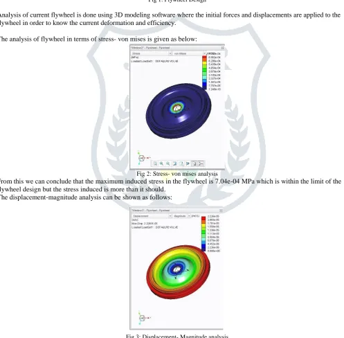
The analysis of flywheel in terms of stress- von mises is given as below:
Fig 2: Stress- von mises analysis
From this we can conclude that the maximum induced stress in the flywheel is 7.04e-04 MPa which is within the limit of the flywheel design but the stress induced is more than it should.
The displacement-magnitude analysis can be shown as follows:
Fig 3: Displacement- Magnitude analysis
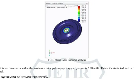
Fig 4: Strain- Max Principal analysis
From this we can conclude that the maximum principal strain acting on flywheel is 5.788e-09. This is the strain induced in the flywheel.
VI.REQUIREMENT OF DESIGN OPTIMIZATION
With a specific end goal to change the outline structure, right off the bat we have to break down the present flywheel which is being utilized by the organizations and choose where the power acting is less so the new plan can be made. There are numerous reasons for disappointment of the flywheel. Most extreme pliable and twisting burdens actuated in the edge and malleable anxieties get prompted in the arm under the activity of divergent powers are the primary driver of flywheel disappointment. In this work pressure assessment in the edge and arm are examined utilizing limited component strategy and results are approved by expository counts. The FE examination is done for various stacking conditions on the flywheel for various cases the most extreme Von-mises stresses and avoidance in the edge are resolved. From this examination, it is dissected that Maximum burdens initiated are in the edge and arm intersection. Because of the use of extraneous powers, most extreme twisting anxieties happen close to the center point end of the arm. It is likewise watched that for low precise speed the impact of gravity on stresses and redirection of edge and arm is prevalent. Due to these reasons, design optimization of flywheel is required.
VII.ANALYTICAL CALCULATIONS REQUIRED FOR FLYWHEEL
The Method Adopted For The Design Of Flywheel For Punching Machine Is Analytical Method. Now Let Us Determine The Various Parameters In Regard With Flywheel Design.
Mean speed of flywheel N= 9
Number of strokes/min =9×30=270 strokes/min
Mass of flywheel, m =fluctuation of energy V2 × Cs =3233.3 = 253.3 Kg
Table 1. Specifications of flywheel
.
Maximum shear stress 339.3 N/mm2 Total energy required, E 3592.6 N-m
Rim Velocity 11.3m/s
Bending moment 496.78N-m
Average torque 63.53N-m
Total stress 10.9066N/mm2
Table.2 Considerations in flywheel
Shaft diameter,ds =34.96 say=40mm Hub diameter, dh = 2ds=80mm Length of hub, lh = 2.5 ds=100mm
Table 3. Dimensions for flywheel
© 2018 JETIR July 2018, Volume 5, Issue 7 www.jetir.org (ISSN-2349-5162)
VIII.NEW FLYWHEEL DESIGN
The new flywheel design has reduced weight which is shown as follows:
The new flywheel is made utilizing the structure of past plan where chamfering and cutting is done trying to decrease its weight. The adjustment in configuration is done from the above given examination by lessening the extent of territories where the heap variety is less.
The geometry of a flywheel might be as straightforward as a tube shaped circle of strong material or might be of talked development like ordinary wheels with a center point and edge associated by spokes or arms.
Little flywheels are strong circles of the empty round cross-area. As the vitality prerequisites and size of the flywheel builds the geometry changes to a plate of the focal center point and fringe edge associated by networks and to empty wheels with different arms. Mass at largest radius contributes much more since the mass moment of inertia is proportional to mr2
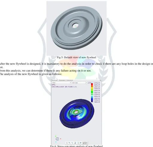
Fig 5: Default view of new flywheel
After the new flywheel is designed, it is mandatory to do the analysis in order to check if there are any loop holes in the design or not.
From this analysis, we can determine if there is any failure acting on it or not. The analysis of the new flywheel is given as follows:
Fig 6: Stress-von mises analysis of new flywheel
From this analysis of stress-von mises we can see that the load acting on flywheel is 3.00e-06 which is far less than the previous flywheel which means the stress induced in this flywheel is less than the previous one.
Fig 7: Displacement-magnitude analysis of new flywheel
Here from this analysis it is evident that the displacement of the flywheel is nearly half than it was in the previous flywheel. The maximum displacement of 1.575e-07 which means that the displacement is negligible when it is in use.
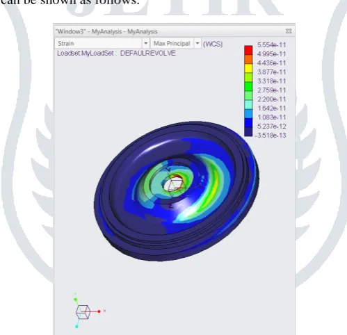
The strain-max principal analysis can be shown as follows:
Fig 8: Strain-Max principal analysis of new flywheel
IX.CONCLUSION
From the analysis it is completely shown that the design of new flywheel is better than the previous on because of it reduction in weight of 3 kilograms and increase in efficiency. Different type of flywheels are designed and analyzed for high reliability and long life. Smart design of flywheel geometry has significant effect on its specific energy performance. Amount of kinetic energy stored by wheel –shaped structure flywheel is greater than any other flywheel. To obtain certain amount of energy stored; material induced in the spoke/arm flywheel is less than that of other flywheel, thus reduce the cost of the flywheel. From the analysis it is found that maximum stresses induced are in the rim and arm junction. Results shows that efficient flywheel design maximizes the inertia of moment for minimum material used and guarantee high reliability and long life. The efficiency of the new flywheel is given as follows:
Efficiency = Directional deformation of new flywheel Directional deformation of old flywheel = 0.000015136
© 2018 JETIR July 2018, Volume 5, Issue 7 www.jetir.org (ISSN-2349-5162)
REFERENCES
[1] Bawane G ―Analysis and optimization of Flywheelijmerr/vol.1/no.2/july2012, pp272-276.
[2] Bolund B, Bernhoff H, Leijon M -Flywheel energy and power storage systems / Renewable and Sustainable Energy Reviews 11 (2007) 235–258.
[3] Bitterly G, “Flywheel technology: past, present, and21st century projections,” IEEE Aerospace and Electronic SystemsMagazine, vol. 13, no. 8, pp. 13–16,1998.
[4] Choudhary M ―Design and Optimization of Flywheel- A Past Review IJMERR/Vol.1,Issue.XII/June 2012pp.1-4 [5] Dhengle M ―Investigation of stresses in arm typerotating flywheelIJEST/vol.4/pp641-650.
[6] Dilip;P.N.,Kamal,R(2010) -An evolutionary approach for the shape optimization of flywheelI.E.(1) journalMC,Vol.90,pp8-12
[7] Forrester, A. I.&Keane, A. J. (2009). Recent advances in surrogate-based optimization, Progress in Aerospace Sciences 45(1-3): 50–79.
[8] Kaftanogly B -Flywheels And Super flywheels Energy storage system/vol. I/213-219.(2010)
[9] Mofid M―An Optimal Two-Dimensional Geometry of Flywheel for Kinetic Energy Storage Int. J. of Thermal& Environmental Engineering Volume 3, No. 2 (2011) 67-72