Published online November 25, 2014 (http://www.sciencepublishinggroup.com/j/ijrse) doi: 10.11648/j.ajae.s.2015020101.18
Numerical solution of solar energy absorbed in porous
medium with a new approach for vapor pressure
calculation and consideration of solute crystallization
Sherif A. Mohamed
1, Ibrahim S. Taha
1, Mahmoud G. Morsy
1, Hany A. Mohamed
2,
Mahmoud S. Ahmed
31
Department of Mechanical Engineering, Faculty of Eng., Assuit University, Assuit, Egypt 2
Mech. Eng. Department, Faculty of Eng., Al Taif University, Al Taif, Saudi Arabia 3
Faculty of Industrial Education, Sohag University, Sohag, Egypt
Email address:
[email protected] (S. A. Mohamed)
To cite this article:
Sherif A. Mohamed, Ibrahim S. Taha, Mahmoud G. Morsy, Hany A. Mohamed, Mahmoud S. Ahmed. Numerical Solution of Solar Energy Absorbed in Porous Medium with a New Approach for Vapor Pressure Calculation and Consideration of Solute Crystallization. American
Journal of Aerospace Engineering. Special Issue: Hands-on Learning Technique for Multidisciplinary Engineering Education.
Vol. 2, No. 1-1, 2015, pp. 93-105. doi: 10.11648/j.ajae.s.2015020101.18
Abstract: The goal of the study is to enhance the productivity of solar stills using an unsaturated porous medium initially
saturated by salty water and using concentrating reflector. This paper concentrates only on the mathematical model for the porous medium and its solution using a finite-volume approach. The previous studies dealt with wick medium with high water content and liquid saturation in the wick medium was not determined. A physical model for the initially saturated porous medium was developed. The model takes into consideration the salt concentration in the solution, surface and internal water diffusions to humid air with vapor pressure determined from vapor mass balance. The system of transient one-dimensional differential equations was developed together with the boundaries and initial conditions. A finite-volume method was used for discretisation of the differential equations. A fully-implicit scheme was used for unsteady term discretisation while the convective terms (liquid solution, vapor and dry air) in the energy equation are handled by an upwind scheme method. The nonlinear equations are solved simultaneously by updating the coefficients matrix at one time step until the five variables converge to prescribed tolerance. Matlab was used as a programming tool. Solution of the model is obtained and discussed.Keywords: Porous Medium, Solute Concentration, Vapor Pressure, Absorbed Solar Radiation
1. Introduction
The study of porous medium represents the importance in industry, drying, soil contaminants and solar still. The wick material can be used in solar still and it can be considered as a porous medium and the nature of study for porous medium is different from that of wick material. The consideration of porous medium helps to make a mathematical model of differential equations, the mathematical model gives the mass and heat transfer in porous medium also it gives the prediction for solute crystallization. Then the novel usage of porous medium is solar still applications. Then the mathematical model can be formed to know both heat and mass transfer knowledge
Ni et al. [1] had developed a multiphase porous media model to predict moisture transport during intensive microwave heating of biomaterials. They formulated the
governing equations and boundary conditions for multiphase moisture transport. They solved the coupled equations numerically, compared the numerical results with convective "non-microwave" heating studies which were reported in their literature. Also they obtained experimental measurements of moisture loss in their study. They assessed the contribution of the convection terms to the energy equation.
Akbar and Haghi [2] studied the heat and mass transfer phenomena occurring within a carpet during combined microwave and convective drying. They analyzed the moisture, temperature, and pressure distributions generated throughout the process.
fluxes. Modeling and simulation of thermal barriers consisting of highly humid porous media was a challenging task. Physical model needed took into account the heat transfer mechanisms, including radiation heat transfer and phase change. Liquid water and water vapor transfers were considered, including the capillary effects for the liquid phase, as well as the air transfer inside the porous medium. They concluded that the mass transfer rate from the thermal barrier to the environment is controlled by the vaporization process and vapor effusion, and not by the convection mechanism.
Neale et al. [4] studied the hygrothermal analysis of buildings which is becoming increasingly utilized for evaluating heat and moisture related problems within the building envelope. They concluded that the convective surface coefficients were particularly important for calculations involving boundary layer heat and mass transfer. The convective moisture coefficients were often calculated through analogy equations, i.e. Lewis and Chilton Colburn ones. However, these equations were not always valid. Therefore, a different approach is needed to accurately determine heat and mass convection coefficients. Murugesan et al. [5] studied numerically the evaporative drying of a two-dimensional rectangular brick. Average heat and mass transfer coefficients appropriate to the conjugate problem were defined based on constant temperature and moisture differentials between the solid and the ambient. Free convection effects on drying were also studied for some initial period for low Reynolds number. It was demonstrated that heat and mass transfer coefficients based on constant temperature and moisture potentials may be more representative of the conjugate heat and mass transfer process during drying. Hence, the conjugation of two coefficients is less representative based on instantaneous temperature difference and moisture difference.
Lee et al. [6] developed a transient two-dimensional mathematical model to simulate the through-air drying process for tufted textile materials. The heat and mass transfer in cylindrical porous medium and air flowing around it were analyzed separately. The resulting system of the three non-linear differential equations was numerically solved by an implicit finite-difference method. Duc Le et al. [7] solved the salt concentration equations in conjunction with the liquid saturation evolution in space and time using numerical and analytical methods for selected cases. The main objective of their study was to combine the advances in the understanding of flow-through evaporation from porous media with solute transport theory and develop a better understanding of evolution of crystallized salt saturation in rocks. The mass of solid salt crystallized was calculated by applying solubility limits on the liquid concentrations for the case of fast crystallization kinetics and capillary-dominated conditions. Koniorczyk and Gawin [8] had taken the salt phase change kinetics into account during the modeling of coupled moisture, salt, and heat transport. Their mathematical model was describing moisture and salt transport in non-isothermal conditions. The process of salt phase change in the pore solution was modeled using the non-equilibrium approach,
where the rate law describing mass change of the crystallized salt is known.
The previous works of wicked solar still did not deal with internal structure of porous media, solar irradiance penetration, utilization of drying period of porous media, crystallization inside pores and effect of partial saturation of the porous medium. However, the studying of heat and mass transfer is considered a surface phenomenon. A porous medium, being a heterogeneous system made of a solid matrix with its void filled with fluids, can be treated as a continuum by properly accounting for the role of each phase in transport through this system of phases [9]. In the previous work of porous medium, the vapor pressure is not taken as a variable in the differential Equations. However, it was not calculated as a variable in the differential equations and the source and sink terms were canceled each other by summing the liquid and vapor mass equations. In the present study, a new approach is presented by calculating the vapor partial pressure using suggested an evaporation model to calculate the vapor source term in the mass vapor equation. Also, the solar radiation attenuation is modeled in the present work to calculate an absorbed solar radiation at the porous medium different layers. Five one-dimensional differential equations expressing mass, momentum and energy equations are
presented in five unknowns
(
)
v
P P C
S, , , . The nonlinear equations are solved simultaneously by updating the coefficients matrix at one time step until the five variables converge to prescribed tolerance. The numerical code is written in Matlab. Solution of the mathematical model is obtained and discussed.
2. Physical Model
Figure 1 shows the system of the current work. The porous material is supposed rigid and unsaturated one with capillary behavior. Mass and heat transfers are supposed to be one dimensional. The closed side (z=0) of material is adiabatic and the open side (z=L) is subjected to natural convective flow and long wave radiation. The solar radiation
(
λ=0.3−3.0µm)
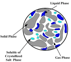
penetrates the porous material and it is absorbed by fluid and solid phases. The model considered in this paper is only that in the porous medium. Figure 2 shows the schematic sketch of porous medium phases.Fig 2. Physical model of non-hygroscopic porous medium
2.1. Assumptions
1. The skeleton of a porous body is a rigid solid which does not swell, absorb water, or dissolve in water and does not enter into chemical interactions with water solution (water/ NaCl solution)
2. The moisture adsorbed due to hygroscopicity of salt is neglected.
3. Transport in the material is simplified by making local thermal equilibrium.
4. The salt movement occurs by convection and Fickian's diffusion.
5. The effects of the salt crystallization on the moisture and ionic transport are taken into account by correcting the material transport properties as a function of the porosity in each time step.
6. The specific heat of the brine is assumed to be dependent on brine concentration.
7. The materials of the porous medium are treated as being continuous and having properties defined everywhere in space.
8. The porous material is homogeneous and isotropic. 9. The gas-phase is ideal in the thermodynamic sense. 10. The vapor mass is transferred by diffusion from
porous medium to ambient.
11. The scattering from reflection in a porous medium bed is neglected.
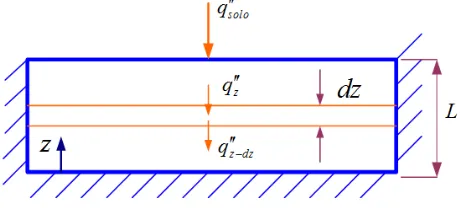
2.2. Attenuation of Solar Radiation inside Porous Medium
The porous medium is assumed to be a semitransparent medium for solar energy which in turn is diffuse radiation. Internal reflection and scattering are neglected and only absorption is taken into consideration. At any location z, the change in radiation flux for the element, as a result of absorption, is a function of the flux reaching the element [10]. The change in intensity has been found experimentally to depend on the magnitude of the local intensity. If a coefficient of proportionality
γ
which depends on the local properties of the medium is introduced, then the decrease in solar flux in an element volume is given by:
′′ +
= ′′
′′ − ′′ =
′′ −
dz t z q z t
z q d
q q t z q d
eff dz z z
) , ( ) ( )
, (
) , (
γ (1)
The quantity
γ
eff is called the effective absorptioncoefficient of the material in the element layer which takes into consideration the absorption in the different components of the porous medium of element thickness
dz
. The absorption coefficient is a physical property of the material and has the units of reciprocal length as it is a volumetric property. The value of γeff is dependent on t and z as do the different component of the porous medium. The radiation flux along the path is attenuated exponentially while passing through an absorbing porous medium. The boundary conditions are:}
solo
z q
q
at z=L, ′′= ′′ (2)
Where:
solo
q′′ is the solar flux impinging on the top surface. The solution is hence given by:
( )
eff(L z)solo
q t z
q′′ , = ′′ exp−γ − (3)
The energy absorbed by an elemental volume per unit
volume is thus equal to z
z q ∂ ′′ ∂
or
(L z)
eff eff solo z q
q′′′= ′′ γ exp−γ − (4)
The latter term is considered as energy generation term in the energy equation of the porous medium. The radiation flux reaching the bottom of the porous medium is assumed to be absorbed at the bottom surface (z=0) of the container holding the porous medium. The latter term is equal to:
( )
( )
effL solosol t q t
q′′ 0, = ′′ exp−γ (5)
2.2.1. Calculation of the Absorption Coefficient for Porous Medium Phases
The absorption coefficients for porous medium phases (solid, solution, gas) are functions of wavelength distribution. Thus, the total absorption coefficient for each phase of the porous medium is calculated from:
∫
∫
= 3.0
3 . 0 0 . 3
3 . 0
λ λ γ γ
λ λ λ
d E
d E
phase (6)
phase
γ
is the medium phase total (average) absorption coefficient −1m
,γ
λ the medium phase spectral absorption coefficient, −1m
,E
λ spectral intensity Wm−2/µ
m ,λ
isthe solar irradiance wavelength, µ m.
The effective absorption coefficient is the volume average of absorption coefficient of all components of porous medium, or
(
)
(
l l v v v p sal s)
eff φSγ φwSγ φS γ φγ
Where,
γ
l is the water average absorption coefficient,γ
v is the vapor average absorption coefficient,γ
s is the sand average absorption coefficient,γ
sal is the salt average absorption coefficient.The liquid water average absorption coefficient is calculated from the data of spectral absorption coefficient which is reported in [11]. Thus, the calculated average value is 350
m
−1 . The water vapor absorption coefficient is calculated from the spectral absorption coefficient and the calculated average value is approximately 10m
−1 [12]. There is a little amount of carbon dioxide which is included to air components. Thus, the larger components of air are nitrogen and oxygen which have no absorption for solar energy. There is no data for absorption coefficient for sand and because 90% of glass is made of sand, the sand absorption coefficient was assumed to be equal the double of that of glass. Glass absorption coefficient is approximately 301
−
m [10] and thus that of glass is taken 60
m
−1 . The absorption coefficient of NaCl is 0.0007 m−1 [13] at wavelength of 1.06 µm . The total average absorption coefficient of NaCl is assumed 0.00071 −
m
through the solarwavelength band since no data is available at other wavelength values.
2.3. Water Vapor Diffusion inside Porous Medium
The vapor pressure is estimated from vapor mass balance and it is solved simultaneously with other four variables. The vapor mass transfer inside the porous medium consists of capillary mass rate, diffusion mass rate through gas (humid air) and evaporation mass rate by diffusion from water solution to porous medium humid air.
2.3.1. Diffusion of Vapor from Water to Solution to Gas To calculate the mass rate of diffusion from water solution to vapor inside the porous medium, it is assumed that the salt solution in an element volume that has the profile of N cylindrical columns each of diameter (d) surrounded by a volume of gas making cylindrical annulus of outer diameter (d+y). The value of y represents the air space around water cylinder and was considered to be 0.0075 m. Thus, diffusion of water solution to humid air occurs from cylindrical surface areas to the surrounding air. The equations for mentioned evaporation model are as follows:
(
)
(
)
− +
= 2 2
4 d y d
N S Acr g
π
φ (8)
2
4d
N S Acr l
π
φ = (9)
From equations 8, 9, the following two equations are derived
2
4
d S A
N cr l
π φ
= (10)
0
2 2
2 =
−
− y
S S d S
yS d
g l
g l
(11)
The values of N and d can be obtained from equations (10) and (11). Since the temperature distribution is one dimensional, evaporation takes place by diffusion from saturated air at the surface of water to the unsaturated surrounding air at the same temperature. The rate of vapor mass diffused from water columns to the surrounding air per unit volume of the porous medium is calculated from:
(
)
dzh A
mɺevap′′′ = sr mp ρvs − ρv / (12)
Where: sr
A
is the ratio of water solution surface areaA
lstocross-section area of porous medium
A
cr and hmp is the mass transfer coefficient between solution surface and humid air. The liquid solution surface area is given by:( )
sr cr ls N d dz A AA = π = (13)
and from eq. (9)
( ) ( )
= =
∴ =
dz d S A
dz d N A
d S A
d N
l cr sr
l cr
4 4
φ π
φ π
(14)
Hence,
(
vs v)
mp l
evap h
d S
m ′′′ = φ ρ − ρ
∴ ɺ 4 (15)
The mass transfer coefficient
h
mp is calculated from [14]:(
) (
)
(
) (
)
=
+
− =
< < =
< < =
=
efg a
efg mp
D Sc
a ha s ha c L ha s ha g Gr where
Sc Gr Sc
Gr Sh
Sc Gr Sc
Gr Sh
dz D Sh h
/
2 , 3 ,
,
10 * 10 3 / 1 * * 1 . 0
10 * 10 * 59 . 0
/ *
13 9
9 5
25 . 0
υ
υ ρ ρ ρ
ρ
(16)
The characteristic length Lc in eq. (16) is taken
( )
y
/
2
.2.3.2. Vapor Mass Transfer from Inside Porous Medium by Capillary and Diffusion
The total flux of vapor is composed of convective (Darcy flow) and diffusion flows respectively as these are given by the following equation [1]:
(
)
∂ ∂ −
∂ ∂ −
= ′′
z P P D M M C
z P KK
m a v eff v
g g
g g r
v v
/ 2
,
ρ µ
ρ
2.4. Soluble and Crystallized Salt Model
There are two approaches for salt crystallization; namely, equilibrium approach and kinetic approach. In the first approach the equilibrium between the dissolved and precipitated salt is assumed. The amount of precipitated salt in the pores is defined by its saturation degree Sp, which is
described by the salt binding isotherms. In this approach, it is assumed that salt solution is not saturated. Due to the physical adsorption, some of ions are captured by the solid skeleton surface [15]. In kinetic approach, it is assumed that there is no salt in the solid phase until the solution solubility limit Csat (i.e. the salt mass concentration of the saturated
solution at its temperature) is reached. After exceeding the maximum salt concentration, the solution is supersaturated.
The supersaturation ratio (i.e. current
concentration/concentration at saturation), the supersaturation is the driving force of the salt crystallization, which starts when the solution supersaturation ratio is greater than one. The first crystals are formed on the crystallization nuclei which are usually built by dust or other contaminations. An increase of solid salt mass is calculated on the basis of the supersaturation ratio, according to the following equation [15]:
(
)
′ < ′
− −
′ ≥ ′
− =
sat p
sat s
l
sat p
sat s
l p
C A C
A C K S
C A C
A C K S
dt dS
s s
C , C ,
(18)
(
p)
(
l(
s ssat)
)
prece K S C A C
mɺ ′′′ = −ρ ′ − ′ , (19)
In equation (18), it is assumed that there is no salt in the solid phase until reaches the solution solubility limit Csat (i.e. the salt mass concentration of the saturated solution at a current temperature) is reached. After exceeding the maximum salt concentration, the solution is supersaturated. Equation (19) represents the precipitated salt mass when the solution is supersaturated. An increase of solid salt mass is calculated on the basis of the supersaturation ratio, according to equation (18). The process order, p, depends on the properties of porous body and the kind of salt [8]. There is a need to determine mass of precipitated solute in the solution (dissolved salt) or a mass crystallized solute. An increase of the mass of dissolved solute has a negative sign which physically means dissolution of salt crystals. It was found from the experiments that the form of rate law and the order of the process p = 1.9 was taken from previous work, where the salt crystallization in bricks was analyzed. The other constants of the rate law were assumed arbitrary due to the lack of the experimental data concerning cement mortar and the rate constant of crystallization of sodium chloride is given at [15].
2.5. Ambient Temperature and Humidity Calculation Method
The ambient temperature was assumed to be correlated as a cosine wave with time with a maximum at 3 p.m. and minimum at 3 a.m. The maximum and minimum temperatures are usually obtained from the meteorological data for different locations (Assuit city was considered for
the current study). The relative humidity is known at 3 p.m. for Assuit. The humidity ratio is assumed to be constant during the day. These assumptions help in estimating the temperature and relative humidity of air at any time during the day. The data of Assuit, Egypt are used in this study.
3. Equilibrium State Laws and
Properties
The input data are shown at table (1) The total porous medium volume is:
p g w
s V V V
V
V =∆ +∆ +∆ +∆
∆ (20)
The porosity is:
V V V
Vw g p
∆ ∆ + ∆ + ∆ =
φ (21)
The water saturation, gas saturation and salt crystallized saturation are defined as:
∆ ∆ = ∆ ∆ = ∆ ∆ =V V S V V S V V
S w g g p p
l
φ φ
φ , , (22)
1
= +
+ g p
l S S
S (23)
The mass density of water vapor and dry air and their mixture are:
+ = + =
= =
a v a v
a a a
v v v
P P P
T R
P
T R
P
, ,
ρ ρ ρ
ρ ρ
(24)
The intrinsic permeability is given by [16]:
( )
(
)
(
)
2 3
0
1 1
1 1
− −
− −
=
p p
S S
K K
φ φ φ
φ
φ (25)
The effective gas diffusion coefficient is given by [1]:
( )
(
(
)
)
34
1
0
p l i
i D S S
D
φ
=φ
− − (26)The effective salt diffusion coefficient is given by [17]:
(
4 2)
93 / 2
, 0.779 0.027 310 10 − −
+ +
=S T x T x
Dsalef l (27)
The capillary pressure is given by [9]:
( )
( )
(
)
(
)
− + − + −
= − −
08 . 0 005 . 0 1
221 . 0 1
364 .
0 401
2 1
l l l
S S e
K
P S
c φ σ
(28)
The capillary diffusivity is given by [1]:
∂ ∂ =
l c
l rl w
S P K K D
The liquid viscosity, thermal conductivity, and surface tension are given by [18]:
(
2 3)
6 5 . 44 1 . 4 85 . 1 1 5 . 1808 exp 10 1 .
2 s s s
l C C C
T
x + − +
= −
µ (30)
w
l C K
K =0.04 + (31)
+ +
= Cs
T 0.04055
15 . 273 93 . 252 exp 03059 . 0
σ (32)
The liquid density is given by [19]:
(
)
= + = 0.7558 1 ε ε ρρl o C
(33)
Relative permeability [9]:
(
)
− = = ≤ − − = 3 3 1 1 1 eff r eff eff ir ir l eff S K S K S S S S S grl (34)
The effective heat capacity and thermal conductivity: ( )ρCpeff=(φSlρlCp,l+φ(1−Sl−Sp)ρvCp,v+φ(1−Sl−Sp)ρaCp,a+φSpCp,cr+( )1−φρsCp,s) (35)
( )
(
)
(
)
( )
(
l p a v l p v l l p cr s)
eff w S S K w S S K SK SK K
K =φ1− v 1− − +φ 1− − +φ +φ +1−φ (36)
Where:
(
)
(
)
2 2100 / 0048 . 0 100 / 396 . 4
4180 l l
pl C C
C = − ρ + ρ [20],
( )
ρ
Cp effisthe porous medium effective heat capacity, Keff is the
effective thermal conductivity of porous medium components,
pl
C is liquid solution specific heat, Kl is the liquid solution
thermal conductivity.
4. Mass and Heat Transfer
Transport in the material is simplified by making the assumption of local thermal equilibrium. This means that at any cross section, the solid, liquid, gas and precipitated salt phases are at the same temperature. This allows the thermal transport to be characterized by a single equation for conservation of energy. Heat transfer model includes conduction, radiation, enthalpy convection, sensible heating and phase change. The partially saturated media raises liquid water solution by capillary action. There is a phase change for liquid water and soluble salt. For the liquid water is being evaporated by diffusion for some periods of time, the salt concentration increases to reach the supersaturation condition. When supersaturation occurs, the salt will be crystallized at dry region of porous media. A realistic model is considered at the exposed boundary in what concerns mass transfer and the outflow mass transfer of vapor is dictated by convective diffusion.
4.1. Governing Equations of Heat and Mass Transfer
The mass and energy conservations are given by the following five equations:
( )
, − ∂ ∂ − ∂ ∂ − = ′′′ + ∂ ∂ g z P KK z m S t l l l l r l evp ll ɺ ρ
µ ρ ρ
φ (37)
( )
(
)
/ 2 , ∂ ∂ − ∂ ∂ − ∂ ∂ − = ′′′ − ∂ ∂ z P P D M M C z P KK z m S t v eff v a g g g g r v evp g v ρ µ ρ ρφ ɺ (38)
(
)
,
∂ ∂ − − ∂ ∂ − ∂ ∂ − = + ∂ ∂ z C D S g z P KK C z S S C t s sal l l l l l l r s l p p l s l φρ ρ µ ρ ρ ρφ (39)
(
)
( ) ∂ ∂ − ∂ ∂ − ∂ ∂ − = ∂ ∂ z P P D M M C z P KK z S t a eff a v g g g g r a a g / 2 , ρ µ ρ ρφ (40)
( )
(
(
)
)
exp − − ′′ + ′′′ − ′′′ − = ′′ + ∂ ∂ − ∂ ∂ + ∂ ∂ z L q h m h m q z T K z t T C eff eff solo cr crs fg evp conv eff effp γ γ
ρ ɺ ɺ (41)
The mass balance equation (37) describes the liquid solution mass transfer. The salt solution leaves the volume across its boundary due to flow moving at Darcy's velocity and takes into consideration gravity force. The mass balance represented by equation (38) describes the vapor mass transfer. The mass balance equation (39) represents the solute mass transfer. The first (LHS) term represents the stored solute and the second term represents the precipitated salt which results from dissolution or crystallization. The mass balance equation (40) describes the dry air mass transfer. Fick’s law governs mass fluxes due to concentrations gradients (diffusion part) which are often the most significant driving force as shown in equations (38), (39) and (40). The modified Navier–Stokes equation for porous media reduces to Darcy’s equation inside the porous media for low-permeability systems [21]. The Darcy's velocity is applied at mass balance equations (37), (38), (39) and (40). The energy balance, equation (41), describes heat transfer inside porous medium. The first (LHS) term is the storage term; the second is the net conduction and convection flux of fluid phases (solution+ vapor+ air). The (RHS) term is the local absorbed solar energy per unit volume. The convection term in the energy equation is defined by the following equation,
(
)
z T m C m C m C z q l pl a pa v pv conv ∂ ∂ ′′ + ′′ + ′′ = ∂ ′′ ∂4.2. Initial and Boundary Conditions
4.2.1. Initial Condition
( )
( )
( )
( )
( )
= = = = =
vi
P z P
i T z T
i P z P
i C z C
i S z S
v ,0
0 ,
0 ,
0 ,
0 ,
(43)
Where:
i
S , Ci , Pi , Ti , and Pvi are the saturation, solute concentration, pressure, temperature, and concentration respectively at time zero.
4.2.2. Boundary Conditions
The bottom (closed) and top (open) boundaries are given as follows:
4.2.2.1. Closed Boundary Conditions
At z=0,
= ′′
= ′′
= ′′
= ′′
0 0 0 0
a salt v l
m m m m
ɺ ɺ ɺ ɺ
(44)
The energy balance at closed boundary is given by:
( effL) solo
eff q
z T
K ′′ −γ
= ∂ ∂
− exp (45)
4.2.2.2. Open boundary Condition
At z=L
It is assumed that P=Pamb, Pamb is the ambient pressure.
The mass balance for liquid, and vapor are given by:
= ′′
′′ = ′′
′′ = ′′
0
2 1
salt evap v
evap l
m m m
m m
ɺ ɺ ɺ
ɺ ɺ
(46)
Where:
1
evap
mɺ′′ is mass flux diffused from solution surface to
ambient air, and mɺevap′′ 2 is mass flux diffused from inner volume humid air to ambient air at surface. The two mentioned fluxes are calculated from:
(
)
(
)
′′ = ′′
− =
′′
vD evap
amb sat v mlv l evap
m m
h S m
ɺ ɺ ɺ
2
,
1 φ ρ ρ
(47)
(
)
(
)
(
)
(
)
(
) (
)
−
− + −
+
−
− + ∆
= ′′
ha N N v a v v
v eff a v
ha v N v N v a v v
eff a v
D v
P P P P M P M RT
P D M M
P P P P M P M RT
D M PM
z m
, , ,
2 ɺ
mlv
h
is the mass transfer coefficient for vapor diffusionfrom porous medium to ambient, vD
m
ɺ
′′
is mass vapor diffusion from humid air in porous medium's surface to humid air region,h
mlv is calculated from [14],3 2
=
α ρ
efg a
D hc
hmlv (48)
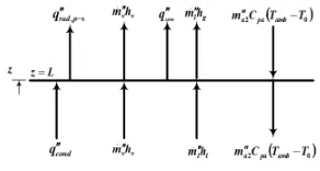
It is assumed that the vapor mass is transferred from porous medium and vapor mass is diffused from porous medium surface to ambient. Wherever the liquid mass is reached to porous medium surface by capillary action, the diffused surface liquid is compensated by it. The water vapor mass transfer coefficient from porous medium to ambient is unknown and there is no experimental data for its value. However, the boundary node for vapor mass transfer is taken as shown in Fig. 3 [22].
Fig 3. The boundary element for vapor mass transfer
The energy balance at open boundary is given by:
out flux Energy in flux ====
Energy
Figure 4 shows the energy fluxes at open surface boundary.
Fig. 4. Open surface energy boundary condition
The heat fluxes enter the top boundary are:
cond
q
′′
the conduction heat fluxl l
h
m
ɺ
′′
the enthalpy flux of liquidv evp
h
m
ɺ
′′
2 the enthalpy flux of vapor diffused from gas toambient
The energy fluxes out from the top boundary are:
conv
q
′′
the convection flux to ambients sur rad
q
′′
, − the radiation flux to skyg evp
h
m
ɺ
′′
1 the enthalpy flux of vapor diffused from liquid toThe energy balance at open boundary can be derived from:
′′ + ′′ + ′′ = ∂ ∂
− effsur mevp hfg qrad qconv
z T
K , ɺ 1 (49)
Where:
( )
(
)
(
)
( )
(
v l p a v l p v l l p cr s)
sur
eff w S S K w S S K SK SK K
K, =φ1− 1− − +φ 1− − +φ +φ +1−φ (50)
The convection and radiation fluxes are given by:
(
)
(
)
−
=
′′
−
=
′′
4 4 c
s sur r
a sur conv
T
T
f
q
T
T
h
q
σ
(51)The heat transfer coefficient from porous medium surface to ambient is given by [14]
(
)
(
Ka wsur Kvwsur)
LcNu
hc = 1− + / (52)
( )
(
)
( )
(
)
(
)
− =
≤ ≤ =
≤ ≤ =
ha p a
c amb ha sur ha aL
aL aL
aL aL
C K
L g
R
R R
Nu
R R
Nu
υ
ρ
ρ
3, ,
11 7
3 / 1
7 4
4 / 1
10 10
15 . 0
10 10
54 . 0
(53)
Both air and vapor properties are calculated at film temperature. Wherever, the concentration difference is between air at the porous medium surface and ambient air, the mass can be transferred from porous medium surface to ambient. Thus, the Grashof number which depends upon the density differences is applicable here [14]. Prantdl number and thermal diffusivity
α
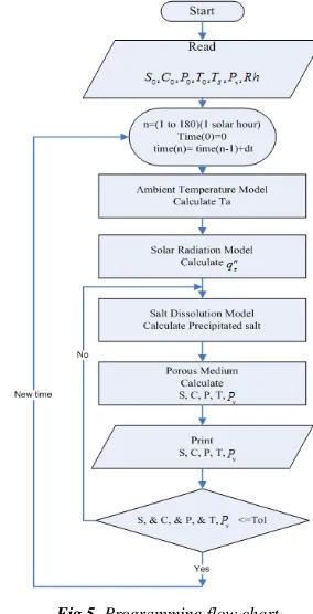
are calculated at humid air conditions.5. Numerical Solution
The finite-volume method is applied to a conservation statement for a control volume.
∫
=∫
•ν
ν
S
dS nˆ V d V
Div (54)
Where
ν
the volume of interest, S is is the boundary surface of the volume,V
is a vector function with continuous first spatial derivatives within the volume, and n is the unit vector normal to the surface oriented to the positive pointing outward from the volume. In Eq. 54, the integral on the left is evaluated over the control volume, which may be a one-, two-, or three-dimensional region, whereas the integral on the right is a contour integral to be evaluated over the boundaries of the control volume [23]. The finite-volume method is applied to a conservationstatement for a control volume. A finite-volume method was used for discretisation of the differential equations. A fully-implicit scheme was used for unsteady term discretisation while the convective terms (liquid solution, vapor and dry air) in the energy equation are handled by an upwind-scheme method. The system of equations is solved by direct method (inverse matrix). The coefficients matrix (K-coefficients) is a function of five dependent variables (liquid saturation, salt solution concentration, gas pressure, temperature, vapor pressure). The nonlinear equations are solved simultaneously by updating (iteration using new solution of variables) the coefficients matrix at one time step until the five variables converge to prescribed tolerance. The numerical code is written in Matlab. The K-coefficients are calculated by an arithmetic average at the interfaces [24]. The convergence is ensured by five convergence criteria for the variables. Figure 5 shows a flow chart for the program designed for numerical solution.
Fig 5. Programming flow chart.
5.1. Time Step and Number of Nodes
1 2 1 1 t cr l N l t cr l N l
l S zA S zA
mass ∆ − ∆
=
∑
ρφ∑
ρφ (55)(
)
∫
+ = 2 1 2 1 t t cr evp evpv m m A dt
mass (56)
∆ = =
∑
∑
= N cr l t solute N cr l t solute z A S C m z A S C m 1 1 0 φ ρ φ ρ (57)The energy balance is given by:
(
)
( )
(
)
(
)
(
)
( )
(
)
(
)
− = ′′ + ′′ + ′′ = − = − ′′ = ′′ ′′′ + ′′ + ′′ =∑ ∑
∫
∑ ∑
∫ ∫
∫
∫
= = = = = = = = = = = =phases tt
L z z o eff p t t L z evp rad out t t phases L z z o eff p a pa a v evp N z ca L z z t t sol t t N z ca t t z c in T T C E I dt q q q E T T C E I T T C M M m q dtdz q q q E 2 2 1 1 2 1 2 1 2 1 0 cov 0 0 1 0 0 . . * / ρ ρ ɺ (58)
6. Results
The porous medium used in this analysis is sand of an average diameter of 0.63 mm. The sand porosity is 0.3. The sand permeability is 11 2
m 10 1 .
2 x − which is considered to be a high permeability [22]. The results of the model were obtained for Assuit location (longitude o E
8 5 0 1
31 ′ ′′ and
latitude27o10′58′′N ) in a summer day (May 22- 2013) from 7:00 a.m. to 2:00 p.m. (solar time). The local solar noon is at 12:03:21. The maximum and minimum ambient temperatures are 311.15 K and 299.15 K and relative humidity is 0.4 at 3:00 p.m. These measurements were obtained from the meteorological data at website for Assuit location in Egypt [25]. The initial condition for liquid saturation, salt concentration and gas pressure are considered to be 0.99,
solution solute kg kg / 035 .
0 and 101.325 kPa, respectively. The ambient
temperature and vapor pressure at 7:00 a.m. estimated to be 302.2 K and 1.58 kPa, respectively, considered to be the initial temperature for the porous medium's components and the initial vapor pressure in the medium's gas.
Figures 6 to 10 show the results of the distributions of the five variables (saturation, concentration, pressure, temperature, vapor pressure) at different times. Figure 6 shows very slight decrease in liquid saturation in the porous medium at the first two hours. However, the saturation values decrease more as time passes almost linearly with z for the same time. The liquid saturation is relatively high in the distance from medium's center to the medium's bottom. The liquid saturation decreases at the front region mainly due to the vapor mass transfer to the surrounding. Wherever, the liquid saturation is decreased, the solar radiation penetrates
more through medium thickness. This causes solar energy absorption to spread deeper to the interior region. The latter explains the increase in the evaporation rate by diffusion in the interior region. This is confirmed by the relatively large vapor pressure in the interior region as shown in Fig. 9 (water vapor pressure distribution curve).
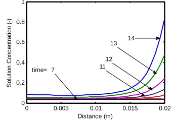
Figure 7 shows the solution concentration profiles. It is clear that the maximum concentration values are at the upper region of the medium. The salt concentration is initially the same for the medium and by water evaporation the salt concentration increases. Firstly, the concentration is approximately taken the initial concentration value because the vapor pressure is approximately equal to the vapor saturation pressure. This leads to small diffusion of vapor from solution to gas for the interior region. At the top Region the concentration increases with increase in z. At the last three hours, there is a relatively large difference in solution concentration between top and interior regions with the maximum concentration occurring at the surface. The soluble solute starts to crystallization at the hour 14 for z=L since the supersaturation ratio has reached to a value of 2.6 and this value is larger than crystallization supersaturation ratio for sodium chloride (2.31) [26].
0 0.005 0.01 0.015 0.02 0 0.2 0.4 0.6 0.8 1 Distance (m) S o lu ti o n S a tu ra ti o n ( -)
time = 7
8 11 12 13 14 9 10
Fig 6. Saturation distribution –date 22/05/13;Time: 7:00- 14:00
0 0.005 0.01 0.015 0.02
0 0.2 0.4 0.6 0.8 1 Distance (m) S o lu ti o n C o n c e n tr a ti o n ( -) 14 13 12 11 time= 7
Fig 7. Concentration distribution –date 22/05/13;Time: 7:00- 14:00
coefficient decreases and the solar flux penetrates deeper in porous medium. This causes the maximum temperature to move deeper in the medium. The maximum temperatures occur at the hour 12 coping with time of almost maximum solar flux.
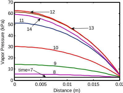
Figure 9 shows the partial water vapor pressure. The vapor pressure is changed at the end of each time interval according to the value of the stored vapor mass in the interval. In Fig. 9, it is clear that the water vapor pressure at surface node has lowest value due to diffusion of vapor to the atmospheric air. However, the surface pressure is changed from 1.58 kPa to 5.0038 kPa and the surface vapor pressure returns to reduce to 4.64 02 kPa at 13 p. m. It is generally clear from Fig. 9 that the water vapor pressure is mainly function of temperature which is responsible for increasing vapor mass by diffusion. The maximum value for vapor pressure is obtained at about the hour 12 (noon) at the bottom region of the medium. This is due to the maximum solar flux beside its deeper penetration in the medium. At this time the lowest vapor pressure is at the surface as expected and discussed before. It is also clear that the vapor gradient in the lower region of medium is relatively small at the first three hours and after that it increases with time till around solar noon. On the other hand, for top region there is always a pressure gradient that increases near the top and increases with time till solar noon. The results obtained for total vapor transferred to atmospheric air was about 8.3 kg for a time period of 7 hours.
0 0.005 0.01 0.015 0.02
300 310 320 330 340 350 360 370
Distance (m)
T
e
m
p
e
ra
tu
re
(
K
)
time=7 8 9
14 10 11
13 12
Fig 8. Temperature distribution– date 22/05/13; Time: 7:00- 14:00
0 0.005 0.01 0.015 0.02
0 10 20 30 40 50 60 70
Distance (m)
V
a
p
o
r
P
re
s
s
u
re
(
k
P
a
)
9 10 11
12
13 14
time=7
8
Fig 9. Water Vapor Pressure distribution– date 22/05/13; Time: 7:00- 14:00
Figure 10 shows the total pressure profiles. It shows an increase in pressure in the first three hours especially in the interior region. The value of increase in total pressure is not exceeding 4 Pa. At first hour, the gas relative permeability
g
r
K is very small since S is relatively large (Eq. 34). The gas l
capillary mass flux term is decreased as
z P
KKrg
∂ ∂
is decreased leading to an increase in the stored mass of vapor and dry air (Eqs. 38 and 40, respectively). At the first three hours, especially for the interior region, the values of K rg and K are small since the liquid saturation is high (see Eq. 34). Also Fig. 10 shows that the total pressure gradient is small. Thus, KKrg Pz
∂ ∂
is small at the first hours; giving high storage terms for vapor and dry air. Hence, the pressure is relatively high at the first hours.
0 0.005 0.01 0.015 0.02
101.325 101.326 101.327 101.328 101.329 101.33
Distance (m)
T
o
ta
l
P
re
s
s
u
re
(
k
p
a
)
9 8
10 11
12 13 14
time= 7
Fig 10. Pressure distribution –date 22/05/13;Time: 7:00- 14:00
7. Conclusions
empirical equations. The change in ambient water vapor pressure affects the water vapor pressure inside the porous medium's elements. The previous studies did not take into consideration the salt concentration with water vapor pressure as variables. This porous medium system can be used with another system such as humid air region in solar still application and it has high dynamically response to the
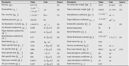
change in the water vapor pressure in the humid air region. The model's equation has taken highly nonlinearity and they strongly have linked, linearization of matrix coefficients is used. The coefficient matrix linearization is occurred by substituting the updated variables into it until the convergence criteria is occurred. Numerical solution gave converging results by applying mass and energy balances. Table (1). Input constant data
Parameter Value Unit Source Parameter Value Unit Source
Porosity ( )φ 0.37-0.5 - [9] Air molecular weight
(
M a)
28.97 kg /kmol [4]Permeability (
0
K )
10 11
10 8 . 1
10 2
−
− −
x
x 2
m [9] Vapor molecular weight
(
M v)
18.015 kg /kmol [4]Gas viscosity
( )
g
µ 5
10 8 .
1 x − Pa-s [1] Salt diffusion coefficient
( )
0i
D 1.5x10⁻⁹ m /2 s
Ambient pressure ( )
0
P 101325 Pa Vapor diffusion coefficient (Dav)
5
10 6 .
2 x −
s
m /2
Air kinematics viscosity
( )
a
υ 1.6x10^-5 m /2 s [8] Irreducible saturation
( )
ir
S 0.08 - [9]
Air thermal conductivity ( ) a
K 0.028 W/
( )
m.K [8] Initial temperature Ta KVapor thermal conductivity
( )Kv
0.0212 W/
( )
m.K [8] Initial Saturation( )
Si 0.99 -Sand thermal conductivity ( )Ks
0.27 W/
( )
m.K [9] Stefan-Boltzmann constant( )
σ 5.67x10⁻⁸ ( 2 4)/mK W [4] Sand density
( )
s
ρ 1530 kg/ m3 Sand emissivity
( )
εs 0.95 -Vapor specific heat
( )
pv
C 1410 J/
( )
kg.K [8] Gravity acceleration( )
g 9.81 2/ s
m Air specific heat
( )
pa
C 1004 J/
( )
kg.K [14] Pure water density( )
w
ρ 998.2 kg/ m3 [15]
Sand specific heat
( )
ps
C 800 J/( )kg.K [4] Sand absorption coefficient
S
γ 60 −1
m
Salt specific heat
(
)
sal p
C , 850 J/
( )
kg.K [27] water absorption coefficient γl 3501
−
m
Vapor gas constant
( )
v
R 0.4615 kJ/
( )
kg.K [4] vapor absorption coefficientv
γ 10 m−1
Air gas constant
( )
a
R 0.287 kJ/
( )
kg.K [4] Sand emissivity( )
s
ε 0.95 -
Nomenclature
A′ supersaturation parameter
C salt mass concentration (kg of solute/kg
of solution)
c phase content
(
3)
m kg
( )
Cp effeffective specific heat
capacity
(
kJ kg.K)
eff
D , effective-diffusivity
(
m2 s)
sal
D salt diffusivity
(
m2 s)
w
D capillary diffusivity
(
2)
s m
q′′ radiation flux(W/ m2)
g gravity acceleration
(
2)
s m
Gr Grashof number;
h enthalpy
(
kJ kg)
c
h convictive heat transfer
coefficient
(
W m2K)
vv m
h , mass transfer coefficient inside porous
medium
(
m s)
mlv
h mass transfer coefficient from surface
porous medium
(
m s)
EI . internal energy
(
3)
m kJ
K thermal conductivity
(
)
K m
kW . and
intrinsic permeability
( )
2m
g r
K, ,Kr,l gas relative permeability (-), liquid
relative permeability (-)
K′ NaCl kinetic parameter
L, LC Porous medium thickness (m),
characteristic length (m)
mɺ′′ mass flux
(
kg m2.s)
evp
mɺ′′′ volumetric evaporation rate
(
kg m3.s)
prece
mɺ′′′ volumetric salt precipitation rate
(
kg m3.s)
a
M , Mv air, vapor
molar mass
(
kg kmol)
=
K L h Nu c c
Nusselt number
P gas pressure
( )
kPaP Precipitated salt
c
P, Pv capillary pressure
( )
kPa , vapor pressure( )
kPa0 ,
r
q
′′
input solar flux(
2)
/ m
W
j
R gas constant for gas
(
kJ kg.K)
(
Sc=υD)
Schmidt number.
=
D L h
Sh m c
Sherwood number;
g
S , Sl gas saturation (-), liquid saturation (-)
p
S precipitated salt saturation (-)
T, TS temperature (K), sky temperature (K)
V volume
( )
3m
Greek Symbols
α thermal diffusivity
(
m2 s)
β volumetric thermal expansion (1/K)
∆ difference value
γ absorption coefficient
( )
1 mυ kinematic viscosity
(
m2 s)
µ dynamic viscosity
(
kg m.s)
a
w humidity ratio of ambient air
sur
w humidity ratio at medium surface.
l
ρ , ρv liquid density
(
)
3
m
kg , Water vapor
density
(
3)
m kg
p
ρ salt crystal density
(
3)
m kg
vs
ρ vapor density of water vapor at saturation
(
3)
m kg
φ porosity (-)
Symbols
eq equation
t time
Subscripts
a air
amb ambient
l liquid
v vapor
sal salt
sat sat
tras transparent
eff effective value
cry crystallization
s sky
sur surface
References
[1] H. Ni, A. K. Datta and K. E. Torrance, Moisture transport in intensive microwave heating of biomaterials: a multiphase porous media model. International Journal of Heat and Mass Transfer, 42 (1999) 1501- 1512.
[2] A. Khodaparast and Haghi, Relations for water vapor transport through fibers. Journal of Computational and Applied Mechanics, 5 (2) (2004) 263- 274.
[3] V.A.F. Costa, M.L. Mendonca, and A.R. Figueiredo, Modeling and simulation of wetted porous thermal barriers operating under high temperature or high heat flux. International Journal of Heat and Mass Transfer; 51(2008) 3342–3354.
[4] A. Neale, D. Derome, B. Blocken and J. Carmerliet, Coupled
Simulation of Vapor Flow between Air and a Porous Material, ASHRAE, 2007.
[5] K. Murugesan, H. N. Suresh, K. N. Seetharamu, P. A. Aswatha Narayana and T. Sundararajan, A theoretical model of brick drying as a conjugate problem, International Journal of Heat and Mass Transfer, 44 (2001) 4075- 4086.
[6] H. Stephen Lee, Wallance W. Carr, Haskell W. Beckham, and Johannes Leisen, A model of through-air drying of tufted textile materials", International Journal of Heat and Mass Transfer, 45(2002) 357- 366.
[7] D. Le, H. Hoang, and J. Mahadevan, Impact of capillary driven liquid films on salt crystallization ". Transp. Porous Med, 80 (2009) 229–252.
[8] M. Koniorczyk, and D. Gawin, Numerical modeling of salt transport and precipitation in non-isothermal partially saturated porous media considering kinetics of salt phase changes. Transp. Porous Med, 87 (2011) 57–76.
[9] M. Kaviany, Principles of heat transfer in porous media, Handbook of Heat Transfer, Second edition, McGraw-Hill, New York, (1995) 2, 28, 479, 491.
[10] M. M. Elsayed, I. S. Taha, and J. A. Sabbagh, Design of Solar Thermal Systems. Scientific Publishing Centre; King Abdulaziz university, Saudi Arabia, (1994).
[11] D. Kraus, Two phase plow in homogenous porous media- The role of dynamic capillary pressure in modeling gravity driven fingering, Master's Thesis, 2011.
[12] Wikipedia, "Electromagnetic absorption by water" (http://en.wikipedia.org/wiki/Electromagnetic_absorption_by_ water)
[13] H. H. Li, "Absorption Coefficients", Int. J. Therm., Vol1, No. I, (1980).
[14] Y. A. Cengel, Heat and mass transfer", Hand book of Heat and Mass Transfer, Third edition, A practical approach, McGraw Hill, New York, 2006.
[15] M. Koniorczyk, Modelling the phase change of salt dissolved in pore water– Equilibrium and non-equilibrium approach, Construction and Building Materials, 24 (2010) 1119–1128. [16] T.Q. Nguyen, J. Petkovic, P. Dangla and V. Baroghel-Bouny,
Modeling of coupled ion and moisture transport in porous building materials, Construction and Building Materials (2007) 1- 11.
[17] J. Bear and A. Gilman, Migration of salts in the unsaturated zone caused by heating, Letters in Mathematical Physics, 19 (1995) 139-156.
[18] S. O. Pstalle, Non-isothermal multiphase flow of brine and gas through saline media, Doctoral-Barcelona, Universitat Politecnica de Catalunya, 1995.
[19] M.C. Boufadel, M.T. Suidan, and A.D. Venosa, Numerical modeling of water flow below dry salt lakes: effect of capillarity and viscosity, Journal of Hydrology, 221 (1999), 55–74.
[21] A. Haldera and A. K. Dattab, Surface heat and mass transfer coefficients for multiphase porous media transport models with rapid evaporation, Food and Bio-products Processing , 90(2012) 475–490.
[22] V.A.F. Costa, M.L. Mendonca and A.R. Figueiredo, "Modeling and simulation of wetted porous thermal barriers operating under high temperature or high heat flux". International Journal of Heat and Mass Transfer; Vol. 51; 2008; 3342–3354.
[23] G. F. Pinder, W. G. Gray, Essentials of multiphase flow and transport in porous media, A John Wiley & Sons, Inc., Hoboken, New Jersey, 2008.
[24] S. V. Patankar, Numerical heat transfer and fluid flow, Book, Publishers, Talyor & Francis, 1980.
[25] Website of " Egyptian meteorological Authority " (http://ema.gov.eg/articles?menu=62&lang=eg)
[26] H. Na, S. Arnold, and A. S. Myerson, Cluster formation in highly supersaturated solution droplets, Journal of Crystal Growth, 139 (1994) 104-112.