Design and Development of Self-Powered
Temperature Measurement and Wireless Data
Transmitting System
K. Ranjithkumar Dharani.M
Assistant Professor Department of Electrical & Electronics Engineering Department of Electrical & Electronics Engineering Kongu Engineering College, Perundurai,
Kongu Engineering College, Perundurai, India India
P.Sai Krishna
Department of Electrical & Electronics Engineering Kongu Engineering College, Perundurai, India
Abstract
In this paper, it has proposed to replace the batteries by thermoelectric generator (TEG) assembly. Usage of batteries in high or medium temperature monitoring system affects the lifetime and required frequent maintenance also. Here TEGs used instead of batteries and output voltage of TEG also measured under various temperature difference level between hot and cold junction. The generated voltage from TEGs boosted and maintained to Three Volt using TPS61200 booster converter. The combination of TEGs and Booster converter investigated under various loaded conditions to test power-delivering capacity. This boosted voltage used to provide energy to the temperature measurement, microcontroller and wireless data transfer circuit in the transmitter module. Microcontroller was programmed to read temperature and to send data at every second once through RF transmitter module.
Keywords: Thermoelectric Generator (TEG), Booster converter, Transmitter module, Thermistor
________________________________________________________________________________________________________
I. INTRODUCTION
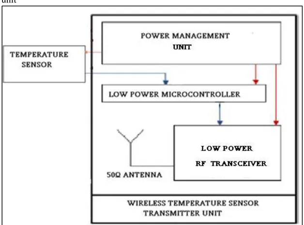
The self-powered Wireless temperature monitoring system, monitors temperature from remote location. The transmitted module consist of following unit.
Power management unit
Design and Development of Self-Powered Temperature Measurement and Wireless Data Transmitting System
(IJSTE/ Volume 3 / Issue 10 / 077)
Power Management Unit
This unit supplies the electrical energy required for the whole transmitter module. Customarily a three-volt battery will act as power source for low power transmitter module. However, due to the following reasons TEGs supersede battery.
Enhances performance
Amends internal discharge or local action losses Reduces cell voltage for a given current
Promotes charging current for a given voltage Minimizes life and required Periodic supersession
Sensing Unit (Temperature sensor)
This unit converts physical quantity (Temperature) into electrical quantity. Here thermistor resistance changes with deference in temperature.
Low Power Microcontroller Unit
MSP430F2274 microcontroller function is to interface and control all units in the transmitter module. It reads analog data from the temperature sensor and converts into digital form. This digital data send to transmitter unit. Also synchronizes all the process in transmitter unit.
R.F Data Transceiver unit
IC-CC2500 Used to send digital data through RF digital transmission mode. It modulates data and transmit through 50-ohm resistance antenna.
II. THERMO ELECTRIC POWER GENERATOR
Principles of Thermoelectric Power Generator
In a typical temperature measurement application, thermocouple A is used as a "reference" and is maintained at a relatively cool temperature of Tc. Thermocouple B is used to measure the temperature of interest (Th) which, in this example, is higher than temperature Tc. With heat applied to thermocouple B, a voltage will appear across terminals Tl and T2. This voltage (Vo), known as the Seebeck emf, can be expressed as:
Vo = Sxy x (Th - Tc)
Thermoelectric Generator Module
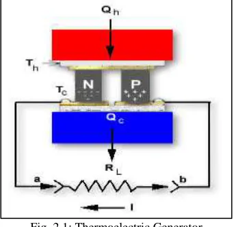
Thermoelectric generators (TEGs) are all solid-state contrivances that convert heat into electricity. It contains no moving components in it. A thermoelectric module used for power generation has certain similarities to a conventional thermocouple. Let us look at a single thermoelectric couple with an applied temperature difference as shown in Figure 2.1
Fig. 2.1:Thermoelectric Generator
Single Thermoelectric Couple where Th > Tc with no load (RL not connected), the open circuit voltage as measured between points a and b is:
V is the output voltage from the couple (generator) in volts. S is the average Seebeck coefficient in volts/°K.
DT is the temperature difference.
The power output Po from the module in watts is:
Po = RL x I2 (3)
It is possible that thermoelectric generators contain a number of individual modules which may be electrically connected in series parallel arrangement. A typical generator configuration is illustrated in Figure 2.2. This generator has a NT number of modules with NS number of modules connected in series and NP number of modules connected in parallel. The total number of modules in the system is [1]-[5]:
NT = NS x NP (4)
Fig. 2.2: Series-Parallel Arrangement of Thermocouples The efficiency of the generator is:
Po
Eg = — x 100% (5) Qh
Where,
Eg is efficiency of the generator. Po is power output in watts Qh is heat input in °K
Performance of Teg Under Different Loads
Design and Development of Self-Powered Temperature Measurement and Wireless Data Transmitting System
(IJSTE/ Volume 3 / Issue 10 / 077)
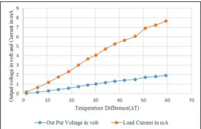
Fig. 2.4: TEG’s response under 1Kohm load
Fig. 2.5: TEG’s response under 750ohm load
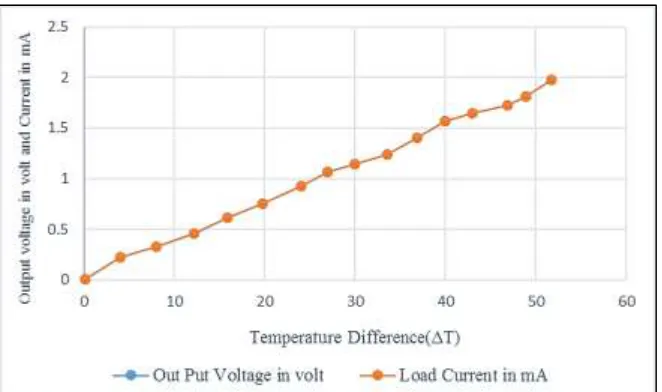
Fig. 2.7: TEG’s response under 250 ohm load Observation
Thermocouple connected and tested across various load conditions. It is observed that Thermocouple can deliver constant voltage to a particular temperature difference irrespective of load values. As the load resistance reduces from no load to 250 Ω resistance, the current value is getting increased. So power sourcing also increased and reached maximum value of 36mW.
III. THERMISTOR IN CIRCUIT
Thermistors are mostly Negative Temperature Coefficient (NTC) characteristics. In order to measure temperature, Thermistors are connected in voltage divider circuit as shown in figure 3.1. As the temperature increases the Vout of the divider circuit increased.
Fig. 3.1: Thermistor in Circuit In the above figure the output voltage
Vout is = 𝑉𝑐𝑐 𝑋 4.7 𝑋10
3
4.7 𝑋103+𝑅
𝑇 (6)
Where,
Vcc is the supply voltage in volt RT is thermistor resistance in ohm
Design and Development of Self-Powered Temperature Measurement and Wireless Data Transmitting System
(IJSTE/ Volume 3 / Issue 10 / 077)
Fig. 3.2: Thermistor output voltage for various temperature levels Observation
From the characteristics of divider circuit, it is observed that as the temperature increases from -40ºC to 125 ºC the output voltage increases almost linearly. So that output voltage will be proportional to the temperature measurement [6]- [10].
IV. POWER MANAGEMENT UNIT USING TEG
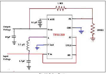
Fig. 4.1: Voltage Booster Voltage Booster
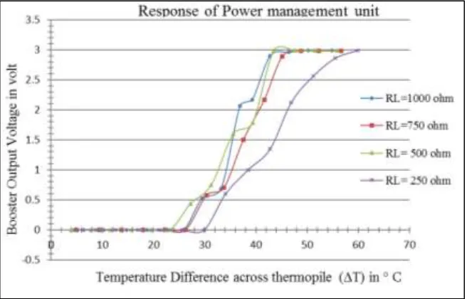
Fig. 4.2: Booster responses Interfacing Booster with Teg
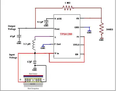
As previously mentioned booster is interfaced with TEGs in order to provide a constant power to the transmitter circuit. Thermocouple is connected at the input of booster converter as shown in figure 4.3. These two combinations are called as power management unit. Positive terminal is connected at the input and negative terminal is connected at the ground.
Design and Development of Self-Powered Temperature Measurement and Wireless Data Transmitting System
(IJSTE/ Volume 3 / Issue 10 / 077)
Fig. 4.4: TEG Interfaced with Booster
From the response of Power management unit, it is observed and concluded that if the temperature difference between hot and cold junction of TEG is maintained above 45 ºC the booster can able to produce and maintain 3 volts in the output.
Power Sourcing Capacity
Power management unit were studied under various load condition in order to study the power sourcing capacity. It is observed from the graph that from the load 250 ohm to 1Kohm power sourcing capacity getting reduce. It almost reaches 36mW for 250ohm resistance (Best case) and 9mW for 1Kohm resistance (Worst case).
Fig. 4.4: Representation of power sourcing capacity Table – 1
Energy delivered by source: Energy supplied for 10 minutes when temperature
difference (ΔT) above 45°C
V. TRANSMITTER MODULE
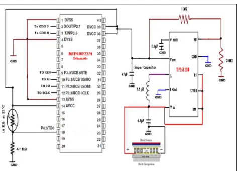
Fig. 5.1: Transmitter Schematic Microcontroller-MSP430f2274
The MSP430 CPU has a 16-bit RISC architecture that is highly see-through to the application. All operations are achieved as register operations in conjunction with seven addressing modes for source operand and four addressing modes for destination operand. The CPU is integrated with 16 registers that provide reduced instruction execution time. The register-to-register operation execution time is one cycle of the CPU clock. Four of the registers, R0 to R3, are devoted as program counter, stack pointer, status register, and constant generator respectively. The remaining registers are general-purpose registers. Peripherals are connected to the CPU using data, address, and control buses, and can be handled with all instructions [12]-[14]
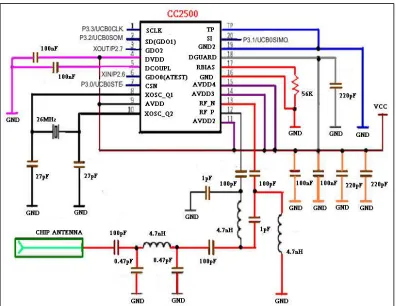
Low Power RF Transceiver using cc2500
Design and Development of Self-Powered Temperature Measurement and Wireless Data Transmitting System
(IJSTE/ Volume 3 / Issue 10 / 077)
Fig. 5.2: Low Power RF Transceiver
Initially turn on frequency synthesizer so that the transceiver is ready to for the operation, at this time it will calibrate and correct the frequency for the operation. Then transceiver activate in transmitter mode by sending a particular register address from the microcontroller. An acknowledgement should be received from the transceiver, the controller checks every second to get acknowledgement from the transceiver. Once microcontroller received acknowledgement, it reads temperature in the form of voltage from data from the potential divider circuit and converts in to digital and send the data to the transceiver register. Transceiver transmits data by FIFO method. Every second once controller reads data and send to transceiver register
Energy Dissipation in Transmitter
Fig. 5.4: Energy Dissipation Calculation
The transmitter module consumes only 0.99 Watt Sec energy. It is observed that energy delivered by source in worst case is 5.4-watt sec, this value almost 5 times higher than the energy consumed by transmitter module. It is concluded and verified that self-powered transmitter module can operate without any battery source.
Fig. 5.5: Measured Temperature Value VI. FUTURE DEVELOPMENT
Design and Development of Self-Powered Temperature Measurement and Wireless Data Transmitting System
(IJSTE/ Volume 3 / Issue 10 / 077)
REFERENCES
[1] Francesco Giuppi; Kyriaki Niotaki; Ana Collado; Apostolos Georgiadis.,(2013) “Challenges in energy harvesting techniques for autonomous self-powered
wireless sensors” Microwave Conference (EuMC), Pages: 854 – 857 Cited by: Papers (1) IEEE Conference Publications.
[2] Pablo Camacho-Medina; Miguel Angel Olivares-Robles; Alexander Vargas-Almeida; Francisco Solorio-Ordaz., (2014)“Maximum Power of Thermally and
Electrically Coupled Thermoelectric Generators”, Pages: 2890-2903; doi:10.3390/e16052890., ISSN 1099-4300., www.mdpi.com/journal/entropy
[3] Alexander Vargas-Almeida; Miguel Angel Olivares-Robles; Pablo Camacho-Medina., (2013). “Thermoelectric System in Different Thermal and Electrical
Configurations Its Impact in the Figure of Merit”, p2162-2180; doi:10.3390/e15062162.
[4] Radek Vlach., “Novel approach to thermoelectric generator modeling as energy harvesting system”.,( 2015). IEEE Conference; ISBN: 978-1-4799-4387-6.
[5] W. Chen; C. Liao; C. Hung; W. Huang, (2012),“Experimental study on thermoelectric modules for power generation at various operating conditions”
Elsevier-vol. 45, no. 1, pp. 874–881.
[6] Stefano Niedd.,( 2012) “High accuracy-wide range resistance measurement for thermistor sensors monitoring”, IEEE Conference ; ISBN:
978-1-4577-1773-4.
[7] J. Supadech; E. Ratanaudomphisut; C. Hruanun; A. Poyai.,( 2008) “Characteristics of silicon thin film thermistors”, IEEE Conference;ISBN:
978-1-4244-2101-5
[8] Jongwon Kim; Jong Dae Kim.,(2011)“Voltage divider resistance for high-resolution of the thermistor temperature measurement” Elsevier-Volume 44,
Issue 10, , Pages 2054–2059.
[9] Chiachung Chen., “Evaluation of resistance–temperature calibration equations for NTC thermistors” Elsevier -Volume 42, Issue 7, August 2009, Pages
1103–1111
[10] Shweta Jagtap ; Sunit B Rane; Suresh Gosavi; Dinesh Amalnerkar., “Study on I–V characteristics of lead free NTC thick film thermistor for self-heating
application”; Article in Microelectronic Engineering 88(1):82-86 · January 2011
[11] Texas Instrument Data sheet -TPS61200- Low Input Voltage Synchronous Boost Converter With 1.3-A Switches.
[12] Texas Instrument Data sheet-MSP430F2274 (ACTIVE)16-bit Ultra-Low-Power Microcontroller. www.ti.com
[13] Beginning Microcontrollers with the MSP430 Tutorial Gustavo Litovsky Version 0.4
[14] MSP430-based Robot Applications: A Guide to Developing Embedded Systems By Dan Harres