Abstract— In this paper we present the design of an Adaptive overcurrent protection for Distribution Power Systems with penetration of Distributed Generation, based in a proposed methodology. The methodology takes into account typical protection schemes, normative, general protection requirements, protections coordination and distributed generation impact to protection system, and its applicable to planning systems or for existing systems initially without DG. This work apply a part of IEEE 13 nodes Radial Distribution test Feeder, to study the impact of Distributed Generation to the protection system, apply and prove the proposed design methodology.
Index Term— Adaptive overcurrent protection, Distributed Generation impact, protection coordination, relay reconfiguration.
I. INTRODUCTION
During last years due to necessity of green energy generation and power economy diversification, Distributed Generation (DG) development has been increasing. With this tendency great benefits are obtained, but also emerge problems and challenges that needs immediately solution by actual engineering.
This work has as objective identify impacts produced to protection systems due to the connection of DG in a distribution grid, therefore it is possible to define protection systems requirements. Based in this requirements, protection schemes, normative and results analysis of the system, this work pretends to develop a methodology that permits a protection system design that fulfill with all the requirements of an special and time-variant system such as distribution grids with DG penetration.
Proposed methodology guides to design an automatic protection system, known as electrical adaptive protection, that take advantage of communication technology and digital relays applications that exist nowadays, for example IED's (Intelligent Electronic Devices). Electrical adaptive protection has to meet with the future of the power grids: automation, flexibility and reliability.
Engineering its responsible to ensure an efficient integration of DG to the grid, for reach economics, technical and environmental benefits. Consequently, it's necessary to
solve problems of protection in microgrids, due to the numerous system operation topologies and configurations, the protection system have to be able to change their parameters to adapt them for new configurations, maintaining the basic criteria of: Sensitivity, selectivity, reliability and velocity, which demands a coordinate protection system.
It is important to highlight that designer have to be responsible to apply this methodology knowing that every distribution system change in its performance and requirements, however, this methodology gives guidelines and defines which aspects and facts will have to be taken into account. For the methodology validation we use a portion of IEEE 13 nodes test feeder.
This paper is organized as follows: Section II presents the study case system which validates the methodology. Section III presents impacts and requirements identified in a power distribution system with DG penetration. Section IV shows the adaptive protection system structure. Section V submits proposed design methodology. Section VI presents the results and advantages of the adaptive overcurrent protection system designed. Section VII concludes.
II. STUDY CASE SYSTEM
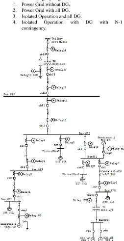
Study case system is a portion of IEEE 13 nodes test feeder [28], one line diagram is presented in Fig. 1, because its characteristics are suitable to study the impact of DG in the overcurrent protection system. DG location and capacity demand a careful analysis and development, that depends of many factors, that doesn't make part of work's approach.
The DG set up in study case are:
- Node 611: Synchronous Generator 1000 kW at 4.16 kV.
- Node 692: Synchronous Generator 500 kW at 4.16 kV.
- Node 675: 2 Units of Wind Turbine Generator 300 kW each one at 0.69 kV,
included transformation 0.69 kV to 4.16 kV.
With DG in the system, exists a lot of possible configuration of the power grids, in this work only has been
Methodology and Design of an Adaptive
Overcurrent Protection for Distribution Systems
with DG
reviewed the following topologies: 1. Power Grid without DG. 2. Power Grid with all DG. 3. Isolated Operation and all DG.
4. Isolated Operation with DG with N-1 contingency.
Fig. 1. Study case system one line diagram, including DG.
III. PROTECTIONS IMPACTS AND REQUIREMENTS IN A SYSTEM WITH DG
We performed a typical design of overcurrent protection to the system without DG, applying Chronometric Selectivity for the instantaneous units (ANSI 50), and time-current Selectivity for temporized units (ANSI 51), for coordinate relays. Using ETAP software is checked the protection coordination, viewing TCC curves, sequence and time of units operation for faults in different buses.
Fig. 2. Protection Coordination example, for a fault at node 611.
Fig. 3. 3Φ and 1Φ fault currents for different system configuration at node 692.
To show clearly the impact of DG to fault currents levels is important to compare current levels for the different topologies respect the current levels for the system without DG.
Fig. 4. Percentage of fault current magnitude (3Φ and 1Φ) for all nodes respects the fault currents of system without DG.
Fig. 5.Percentage of fault current magnitude (3Φ and 1Φ) for all nodes respects the fault currents of system without DG.
Hence, Table I shows the impacts of DG to protection systems in a distribution power grid.
TABLE I
DG's IMPACT TO PROTECTION SYSTEM
# IMPACT OBSERVATION
1 Change fault current flow
Current flow isn't radial with DG, there are current contributions from DG, that are above or/and below faulted point.
2
Increase or Decrease of fault
current
Depends of system operation topology.
3 Incorrect Fuse Operation
It's possible that become ineffective or blow off without a real fault.
4 False Relay trip Due to nominal current flow increase
5 Loose of Coordination
Loose of sensitivity and selectivity, as a result of fault's current magnitude, direction and flow change.
6 Undetectable Faults When new fault current level is low.
7 Interruption Devices Damage
As a result of fault current increase and be greater than interruption capacity of implemented devices.
8 1Φ fault greater than 3Φ fault Due to DG have greater one phase fault current
9 Necessary
Bidirectional Relays Due to Impact number 1
10
Fault current magnitude out of tripping range relay
scale
It is possible that new fault current magnitude (regardless increased or decreased) isn't sensed by relay with the Current Transformer relation initially installed
11 Fault relay trip out of time
Relay trip due to fault, but with too long time that becomes unacceptable. Owing to coverage loose from units 50
For study case system, with different configuration we have the percentage average change of fault current magnitude respect the system without DG presented in Table II.
TABLE II
Magnitude fault current percentage respect system without DG
Configuration 3Φ Fault Current [kA] 1Φ Fault Current [kA] Power Grid
without DG 100,00% 100,00%
P. Grid + DG
complete 128,00% 241,00%
Isolated Op. +
DG complete 35,60% 110,00%
Iso la te d Op . + GD w it h c o n ti n g en cy N -1 G1 no
connected 11,99% 39,43%
G2 no
WTG no
connected 35,60% 117,00%
Adaptive protection system requirements are:
TABLE III
ADAPTIVE PROTECTION SYSTEM REQUIREMENTS
# REQUIREMENT OBSERVATION
1 DG special protection Implement appropriate protection scheme for DG sources [17]
2 Selectivity
3 Adaptability
Whether DG operation and system topology, unit's 50 and 51 configuration are reprogrammed to fulfill protection objectives according to new fault currents.
4 Velocity Appropriate trip time for fault clearing.
5 Individual Relay Evaluation
Depending of system configuration, because it's possible that specific downstream relay in some configuration have to be coordinated as an upstream relay.
6 WTG 3Φ Asymmetric contribution
WTGs don’t contribute 3Φ symmetric fault current, even though it contribute at single line ground fault. 3Φ Asymmetric contribution will affect interruption devices capacities.
7 Identify Bidirectional
Relays Due to Impact number 9 of Table I
Table II shows a percentage average change that is constant for fault current at each node for every configuration respect system without DG. This performance will be used for make adaptive overcurrent protection.
IV. ADAPTIVE OVERCURRENT PROTECTION FOR DISTRIBUTION NETWORKS WITH DG
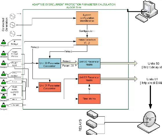
Adaptive protection system proposed, modify automatically relay trip parameters based on system topology detection, maintaining every time an electrical overcurrent protection coordinated at selectivity and sensitivity, as it is defined in [22]. System topology detection is made by knowing which generators are connected. An algorithm is programmed in MATLAB, for evaluate the performance of the adaptive protection structure proposed, this algorithm its the tool for install at control unit (i.e. PLC, master control, etc) that determine new relay parameters. Fig. 6 shows adaptive protection system structure. New relay parameters are calculated taking advantage of Table I information, changing original protection system parameters in proportion to the percentage change presented.
Fig. 6. Adaptive Protection Relay programming Algorithm structure.
Algorithm needs only information from designer, the advantage is that this information exclusively corresponds to protection coordination of system without DG, which is commonly used radial coordination:
a) Number of relays
b) 50 and 51 parameters for system without DG. c) Table I information.
d) Current Transformers transformation relation. e) Fault currents at each node for system without DG. f) Protection coordination time constants, such as:
minimum time (Tmin) and margin time (Tmargin).
Algorithm calculates parameters for units 50 from Trip Current and time delay defined for system without DG, modifying the Trip current on calculus proportionally with percentages for each configuration. Time delays are defined according to coordination required, following current and chronometric coordination. For an identified configuration, the algorithm calculate units 51 parameters for each relay, from the information of this units parameters for the system without DG, using information of Table II, obtains proportional new fault currents. The unit 51 parameters are calculated using Time- Current coordination method (Using ANSI extremely inverse Curve). Although, algorithm permits to change coefficients to obtain another ANSI curves. For this calculation, algorithm constantly saves the trip times for the same relay and respect above and below relays in a time matrix. Algorithm gives the results in 2 matrixes, one for information of units 50 and another for 51.
V. DESIGN METHODOLOGY
protection system methodology is proposed.
1. Analyze the system without DG, identifying special characteristics and carry out Short Circuit analysis. 2. Locate overcurrent protection devices, dividing
system in zones.
3. Apply Asymmetric fault currents calculated in step 1 to find interruption capacity for device in every location. [15]
4. Choose type of relays.
5. Choose and apply Protection coordination method. 6. Verify protection coordination with a software tool,
identifying special requirements.
These 6 steps are already carried out if is an existing systems, that will implement DG.
7. Include DG to the system (This step is a result of a complete study that determine optimally capacity and location). [3][4]
8. Identify type of DG for define protection scheme specifically for the type of source. [17][21]
9. Realize Short Circuit Analysis for possible system configurations with DG, as shown above, it is enough to find fault current for just one faulted node, and find the percentage change.
10. Verify system zones made in step 2, if demands any change.
11. If percentage changes in step 9 are significant, find new asymmetrical fault currents for review device interruption capacities. [15]
12. Define if it is necessary to change protection coordination methodologies.
13. Use Adaptive Protection algorithm proposed: Sign in information obtained in step 1, 5 and 9 to scheme presented in section IV.
14. Use Adaptive Protection algorithm proposed: Verify the relay parameters for all system configurations given by proposed protection algorithm applying a software tool.
15. Realize necessary adjustments and modifications. 16. Verify protection coordination for all system
configurations.
VI. ADAPTIVE PROTECTION SCHEME RESULTS
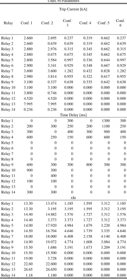
Sample results of methodology and adaptive protection scheme proposed, and applied in the study case are presented in this section, testing that this methodology and algorithm is programmable and works fine, because gives correct results. Table IV, shows the results calculated by algorithm for units 50 for all relays at every configuration. Table V, presents the trip relay sequence for different faults at configuration 2 (Power Grid + DG complete).
TABLE IV
Units 50 Parameters
Trip Current [kA]
Relay Conf. 1 Conf. 2 Conf.
3 Conf. 4 Conf. 5 Conf.
6
Relay 1 2.660 2.695 0.237 0.319 0.662 0.237 Relay 2 2.660 0.639 0.639 0.319 0.662 0.639 Relay 3 2.880 2.976 0.315 0.345 0.662 0.315 Relay 4 2.880 0.675 0.675 0.345 0.662 0.675 Relay 5 2.800 3.584 0.997 0.336 0.644 0.997 Relay 6 2.900 3.341 0.929 0.348 0.667 0.929 Relay 7 3.600 3.600 1.282 0.432 0.828 1.282 Relay 8 2.980 3.814 0.955 0.322 0.617 0.955 Relay 9 3.100 0.337 0.638 0.335 0.642 0.638 Relay 10 3.100 3.100 0.000 0.000 0.000 0.000 Relay 11 3.800 0.746 0.000 0.000 0.000 0.000 Relay 12 4.520 4.520 0.000 0.000 0.000 0.000 Relay 13 7.995 7.995 0.000 0.000 0.000 0.000 Relay 14 0.236 0.236 0.000 0.000 0.000 0.000
Time Delay [ms]
Relay 1 0 0 300 0 1300 300
Relay 2 200 300 250 200 1100 250
Relay 3 300 0 400 300 900 400
Relay 4 600 250 150 600 600 150
Relay 5 0 0 0 0 0 0
Relay 6 0 0 0 0 0 0
Relay 7 0 0 0 0 0 0
Relay 8 0 0 0 0 0 0
Relay 9 600 300 300 800 300 300
Relay 10 900 300 0 0 0 0
Relay 11 0 400 0 0 0 0
Relay 12 100 100 0 0 0 0
Relay 13 0 0 0 0 0 0
Relay 14 300 300 0 0 0 0
xIn
TABLE V
Trip Relay Sequence
System Topology # 2
Fault at Node
611 684 671 675 692 632 Bus 5
Relay
Relay 1 1 5
Relay 2 3 3 2 3 2
Relay 3 1 4
Relay 4 2 2 1 1
Relay 5
Relay 6 1
Relay 7 2
Relay 8
Relay 9 3 3 2 3 2 2 2
Relay 10 2 2
Relay 11 5 5 3 3
Relay 12 1
Relay 13 1
Relay 14 2
Relay G1 4 4 4 4 3 4 5
Relay G2 5 5 5 4 5
Relay WTG
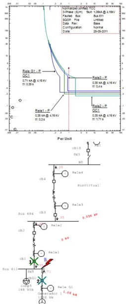
Next figures show the TCC of relays and operation of reprogrammed relays by proposed algorithm. TCC are normalized respect fault current of the faulted node.
TCC in Fig. 7 are for relays 2, 3, 4, 9 and G1, this group of curves don't seem like usually coordinated relays, that's because this system branch have a DG unit at the end, that causes bidirectional fault current flow. For a fault at G1 bus, it's necessary to coordinate system relays for a common radial fault current, if G1 protection is well programmed, but for a fault at bus 684, fault current have component from above and below current contribution, so it's necessary to take into account and develop an appropriate coordination. Sequence shows that exist trips for both contributions, which also have a coordinated back up.
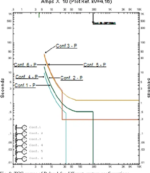
Configuration # 4 becomes a radial system, although it's an operation with DG, hence, TCC are viewed as a typical case of protection coordination for distribution system, instead of results are due to parameters calculated by the algorithm and scheme proposed. It is presented in Fig. 9.
Fig. 8. Faulted bus 611 for system configuration #4. TCC relays that operates and operating sequence in one line diagram.
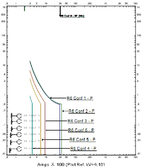
Fig. 9 and Fig. 10 show TCC curves for 2 example relay at different system configuration, this curves are programmed by proposed algorithm scheme results. In this way, designer would visualize the adaptive performance of protection curves, calculated by proposed algorithm.
Fig. 10. TCC curves of Relay 6 for different system configurations.
These results show some advantages for this adaptive protection scheme, some of them are: For take decisions, system only needs a binary information of DG status (On/Off); Algorithm just needs information of original system, it means, system without DG (i.e. Parameters 50 and 51 of relays), being an advantage when the methodology is applied to a constructed system. Due to trip decision occurs locally in relay, sure more reliability, thus only the reprogram parameters depends of a centralized control. This algorithm not only is an adaptive protection tool, furthermore is a methodology for design protection coordination to systems with more than one configuration. Scheme has flexibility to change protection design parameters and curve type, ensuring results that coordinate relays. Also, if the system increase the load, it's just necessary to change the I trip original vector, and the adaptive protection take into account this system change.
Comparing with another adaptive protection methods, as for example [2] [7] [10] [11] [12] , proposed scheme is efficient and take into account impacts and requirements that other methods don’t. The advantage is that it was created later of an strict DG impact to protection system study, realized in this work. Application of this adaptive protection system with this kind of performance, flexibility and versatility would be take important role for nowadays automation and security of electric power systems.
VII. CONCLUSIONS
Results show that methodology and design adaptive protection system proposed is applicable and works effectively for existing power distribution systems, which lately install
DG to get their benefits. Methodology defines necessary steps that designer have to watch and carry out for design an adaptive protection scheme for this kind of power system. Following this steps, designer ensures take into account protection requirements, impacts and corrective actions for distribution systems with DG penetration.
For each system configuration exist a percentage change of fault level respect system's levels without DG, and this is the same change for all nodes, this behavior has been used as calculation variable for reprogram relay's parameters, building up an adaptive scheme. That's why, its sufficient to calculate only a fault current in each configuration at only one node, and compare this fault level with the same fault node in original system and this percentage variation will be applied for all node's fault level. So, it is possible to calculate the parameters for all the relays only knowing original protection coordination of the system without DG and the percentage variation of fault levels.
This work permits identify how DG impacts overcurrent protection in distribution power systems, considering DG types performance. It shows that the most dramatic impact is in isolated operation, because fault currents decay to extremely low values. A challenge that it's necessary to face is with the coordination due bidirectional fault current flow, designer criteria have to be precisely to decide how to coordinate units for response correctly in this cases.
Experience of this work, evidenced that the best coordination method to apply, is programming units 50 only for trip when a fault in the local bus occurred, and make back up only with 51 units. Hence, is recommended to use amperimetrical coordination to units 50 and time - current coordination between adjacent 51 units.
Future research and work in this area is to carry out physical implementation of the adaptive protection system, applying Real Time - Hardware in the Loop simulation (HIL). RT-HIL simulation is based in software simulation of common performance of a power system with DG, a physical controller such as a PLC, for program proposed algorithm and a multifunction digital relay(s). Obtain from de virtual simulation the information needed by proposed algorithm, and send this data to controller which is responsible to calculate and give the information to modify relay protection parameters. Finally obtain real TCC using secondary current injection to relays with an universal relay test set and commissioning tool.
VIII. REFERENCES
[1] B. Hadzi-Kostova, Z. Styczynski, R. Krebs. "New protection concepts for distribution systems with dispersed generation," Power Tech, 2005 IEEE Russia , vol., no., pp.1-6, 27-30 June 2005
[3] C. Tautiva, A. Cadena, "Optimal placement of distributed generation on distribution networks," Transmission and Distribution Conference and Exposition: Latin America, 2008 IEEE/PES , vol.no., pp.1-5, 13-15 Aug. 2008
[4] C. Tautiva, A. Cadena, F. Rodriguez. “Optimal Placement of Distributed Generation on Distribution Networks”, Universities Power Engineering Conference (UPEC), 2009, pp. 1-5.
[5] C.J. Zapata. “Protección de Sistemas de Transmisión y Distribución de Electricidad”, Universidad de los Andes, 2009. [6] C.X Wu, F.S. Wen, Y.L. Lou , "The existed problems and
possible solutions of micro-grid based on distributed generation," Electric Utility Deregulation and Restructuring and Power Technologies, 2008. DRPT 2008. Third International Conference on , vol., no., pp.2763-2768, 6-9 April 2008 [7] Dingding Yuan, Ning Zhang, Xinzhou Dong, Z.Q. Bo, A.
Klimek, "An adaptive noncommunication protection for distribution systems," Universities Power Engineering Conference, 2007. UPEC 2007. 42nd International , vol., no., pp.257-261, 4-6 Sept. 2007
[8] J. Driesen, R. Belmans. “Distributed Generation: Challenges and Possible Solutions”, IEEE Power Engineering Society General Meeting, 2006, pp 1-4.
[9] E. Reihani, R. Norouzizadeh, M. Davodi, "Adaptive Protection of Distribution Grids with Distributed Generation," Power and Energy Engineering Conference (APPEEC), 2010 Asia-Pacific , vol., no., pp.1-4, 28-31 March 2010
[10]E. Sortomme, M. Venkata, J. Mitra, "Microgrid protection using communication-assisted digital relays," Power and Energy Society General Meeting, 2010 IEEE , vol., no., pp.1, 25-29 July 2010
[11]H. Cheung, A. Hamlyn, C. Yang, R. Cheung. “Network-Based Adaptive Protection Strategy for Feeders with Distributed Generations”. IEEE Canada Electrical Power Conference, 2007. [12]Han Yi, Hu Xuehao, Zhang Dongxia, "A new adaptive current protection scheme of distribution networks with distributed generation," Sustainable Power Generation and Supply, 2009. SUPERGEN '09. International Conference on , vol., no., pp.1-5, 6-7 April 2009.
[13]Helen Cheung, A. Hamlyn, Lin Wang, G. Allen, Cungang Yang, R. Cheung, "Network-integrated adaptive protection for feeders with distributed generations," Power and Energy Society General Meeting - Conversion and Delivery of Electrical Energy in the 21st Century, 2008 IEEE , vol., no., pp.1-8, 20-24 July 2008
[14]IEEE. “551 – IEEE Recommended Practice for Calculating Short Circuit Currents in Industrial and Commercial Power Systems”, IEEE, 2006.
[15]IEEE. “C37.010 - IEEE Application Guide for AC High-Voltage Circuit Breakers Rated on a Symmetrical Current Basis”, IEEE, 1999.
[16]IEEE. “IEEE Std. 141 – IEEE Recommended Practice for Electric Power Distribution for Industrial Plants”, IEEE, 1993. [17]IEEE. “IEEE Std. 242 – IEEE Recommended Practice for
Protection and Coordination of Industrial and Commercial Power Systems”, IEEE, 2001.
[18]J.A.P. Lopes, "Integration of dispersed generation on distribution networks-impact studies," Power Engineering Society Winter Meeting, 2002. IEEE , vol.1, no., pp. 323- 328 vol.1, 2002
[19]Kauhaniemi, K.; Kumpulainen, L.; , "Impact of distributed generation on the protection of distribution networks," Developments in Power System Protection, 2004. Eighth IEE International Conference on, vol. 1no pp. 315 – 318 Vol. 1, 5 – 8 April 2004
[20]M.T. Doyle, "Reviewing the impacts of distributed generation on distribution system protection," Power Engineering Society Summer Meeting, 2002 IEEE , vol.1, no., pp.103-105 vol.1, 25-25 July 2002
[21]NFPA. “NEC: National Electrical Code Handbook”. Octava Edicion, NFPA, 1999.
[22]P. Mahat, Z. Chen, B. Bak-Jensen, C. Leth Bak. “A Simple Adaptive Over-Current Protection of Distribution Systems with Distributed Generation”, IEEE PES Transactions on Smart Grid, 2010, pp. 1-10.
[23]P. Vermeyen, J. Driesen, R. Belmans, D. Van Dommelen, "Effect of Embedded Induction Generators on Short-Circuit Detection," Power Systems Conference and Exposition, 2006. PSCE '06. 2006 IEEE PES , vol., no., pp.1363-1370, Oct. 29 2006-Nov. 1 2006
[24]P.P. Barker, R.W. De Mello, "Determining the impact of distributed generation on power systems. I. Radial distribution systems," Power Engineering Society Summer Meeting, 2000. IEEE , vol.3, no., pp.1645-1656 vol. 3, 2000
[25]R. Benato, R. Caldon, S. Corsi, Protection requirements in distribution systems with high penetration of DG and possibility of intentional islanding," Electricity Distribution, 2005. CIRED 2005. 18th International Conference and Exhibition on , vol., no., pp.1-4, 6-9 June 2005
[26]S. Lim, M.S. Choi, S. Jae Lee. “Adaptive protection setting and coordination for Power Distribution Systems”. The Eleventh International Middle East Power Systems Conference (MEPCON), 2006.
[27]T.M de Britto, D.R. Morais,; M.A. Marin, J.G. Rolim, H.H. Zurn, R.F. Buendgens , "Distributed generation impacts on the coordination of protection systems in distribution networks," Transmission and Distribution Conference and Exposition: Latin America, 2004 IEEE/PES , vol., no., pp. 623- 628, 8-11 Nov 2004
[28]W.H. Kersting. “Radial Distribution Test Feeders”, Distribution Systems Analysis Subcommittee Report, IEEE, 2000.
[29]Wei Wang; Zhen-Cun Pan; Wei Cong; Chun-Guang Yu; Feng Gu; , "Impact of Distributed Generation on relay protection and its improved Measures," Electricity Distribution, 2008. CICED 2008. China Internacional Conference on , vol., no., pp.1-5, 10-13 Dec. 2008
[30]Z.AM. Javadian; M.R. Haghifam. “Designing a new protection system for distribution networks including DG”. IEEE Xplore. [31]A. Oudalov; A. Fidigatti. “Adaptive Network Protection in
Microgrids”. ABB Switzerland Ltd.
IX. BIOGRAPHIES
Andres Felipe Contreras C. was born in Bogota, Colombia on February 5, 1989. He graduated with a Bachelors degree in electrical engineering from Universidad de los Andes (Bogota, Colombia) in 2011, and is Master of Science student in electrical engineering at Universidad de los Andes (Bogota, Colombia). (email:
Gustavo A. Ramos received a degree in electrical engineer (1997) from Universidad Nacional, Manizales, Colombia and M.Sc. (1999) and PhD (2008) in electrical engineering from Universidad de Los Andes, Bogotá, Colombia. Currently, he is Assistant Professor at the Department of Electrical Engineering at School of Engineering,
Universidad de Los Andes, Bogotá. (email: