Coalescing A* Algorithm and CLS Method for
Improving Underwater Sensor Networks
Sayyeda Nashiah Nousheen S. Sangeetha
Department of Information Technology Department of Information Technology KCG College of Technology KCG College of Technology
P.N.Devi Ms. R. N. Sharmila
Department of Information Technology Department of Information Technology KCG College of Technology KCG College of Technology
Abstract
Underwater Sensor Network (UWSN) is an emerging network exemplar which consists of underwater sensors that perform monitoring and resource exploration tasks over a given area. The UWSNs have high potential for monitoring the health of marine environments. The major drawbacks in UWSNs is the long propagation delay and draining of node’s energy, which reduces network lifetime. In order to overcome these snags, the combined localisation-synchronisation algorithm, which increases network lifetime by combining location and time synchronization information of nodes, and A* algorithm, which reduces the propagation delay by allowing packet transmission in multiple paths, has been coalesced. The proposed method collaboratively reduces propagation delay and increases network lifetime. It improves various QoS parameter such as throughput, end to end delay, packet delivery ratio and network lifetime.
Keywords: Underwater sensor networks (UWSNs), Localisation-synchronisation, path-finding, Quality of service (QoS) ________________________________________________________________________________________________________
I. INTRODUCTION
One of the enabling technologies for the development of future ocean-observation systems and sensor networks is Wireless information transmission through the ocean. Applications of underwater sensing range from, oil industry to aquaculture, instrument monitoring, pollution control, climate recording, and prediction of natural disturbances, search and survey missions, and study of marine life. The advancements in underwater sensor networks technologies enabled large scale underwater wireless sensor networks deployment in ocean. Due to the ease of deployment of sensor nodes, underwater wireless sensor networks have a vast range of applications such as monitoring of oceanic environment and rescue missions. An underwater wireless sensor network is made of spatially distributed sensor nodes, used to monitor environmental or physical conditions like pressure, temperature, motion, etc. The sensor nodes are deployed with the main objective to gather useful information from the field in an effective way. Relying on the assumption that nodes are equipped with self-navigation systems, these are accurate for use in short periods of time [1]. They typically have a low-power processor, a memory, a transceiver, and a power source. UWSNs generally consist of a base station, which can communicate wirelessly with the sensor nodes. The sensor nodes collect data, compress it, and transmit it to the base station directly or indirectly through other sensor nodes present in the network using routing algorithms.
II. PROBLEM DOMAIN
For efficient monitoring, it is required that the accurate position of node is known, from where the information is detected. For this reason, in underwater communication, usually localization and time synchronization of nodes is necessary. When these two work together, the energy of nodes is saved, thus increasing network’s lifetime.
An important factor to consider is the attribute of sound waves. Most previous researches assumed that the sound speed in underwater communication is either constant or unknown [2]. In UWSNs, sound speed varies with depth, called “stratification effect”. An approach for combined localization and synchronization in UWSN, considers the stratification effect compensation. This approach is based on packet exchanges between anchor nodes and other nodes using directional navigation systems employed in nodes to obtain accurate motion estimates of nodes.
To reduce propagation delay and increase efficiency of packet transfer, it is necessary to maintain a list of cost effective paths. For this purpose, A* algorithm is used for optimal path-finding, which refers to finding the shortest route between two end points [4].
IV. OVERALL ARCHITECTURE
The proposed architecture provides a solution for reducing the propagation delay in Under Water Sensor Networks. The main goal of the architecture is to provide: Reduced propagation delay, increased network lifetime, Time and Location synchronization o f sensor nodes and optimal path selection.
Fig. 1: Overall Architecture for propagation delay in UWSN’s
Node Deployment
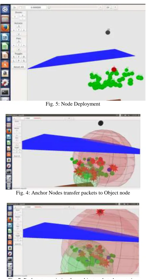
Initially, a network is formed where sensors are deployed in the Acoustic channel. The network may have static surface buoys and base station and anchor nodes. The remaining deployed sensors will be non-static. The network will have a non-static Object node, which will get information from anchor node and sends to base station via surface buoys.
Anchor Node Selection
Anchor points selection is a crucial step of the data gathering process since it determines the efficiency of energy transferring and the latency of data gathering. A trivial scheme is to simply visit all the sensor nodes, gather data and store it. Anchor nodes are selected based on the energy limits. Anchor nodes are used for gathering data easily from the neighboring sensor and sending the data to base station using object node [7].
Time and Location Synchronization
Time and Location Synchronization is used to find out the nodes exact position at a particular time. The CLS (Combined localization and synchronization) Algorithm, for synchronizing the time and location of each sensor nodes is used. It involves Localization with Iteration [2].
Path Finding
V. ALGORITHMS USED
Combined Localisation – Synchronisation Algorithm
The combined localisation-synchronisation algorithm is an approach where localization and time synchronization of nodes work together with the aim to save nodes energy.
Fig. 2: Workflow of combined localisation-synchronisation algorithm
Step 1: Using TOA for Initial Locations
In order to calculate ordinary node’s initial location, it is assumed that the ordinary node has been synchronized. This means that initial clock skew is assigned “1”, and initial clock offset is assigned “0” [6].
Step 2: Quantization of Nodes
The set of possible input and output values may be infinitely large, and may possibly be continuous and therefore uncountable. Thus quantization is necessary [10]. In this step, the locations of the ordinary node and the anchor nodes are quantized so that multiple ToA communication measurements are associated with the same pair of quantized locations. To quantize the anchor nodes, packets are associated with the same set of anchor nodes.
Step 3: Synchronisation of Nodes
The packets required to synchronize all nodes is the function of a number of hops over a temporarily fixed routing path. Synchronization of nodes is the process of making two or nodes have the required information at a given time.
Maintaining accurate timing, or synchronization, in underwater networks is necessary to ensure overall performance is maintained.
Packet delay is defined as the time between the first attempt to send a packet and the successful reception of this packet. Once synchronized the delay reduces by 35% [8].
Step 4: Localization with Iterative Refinement
In this step localization is performed using propagation delay estimates [2].
A* Algorithm
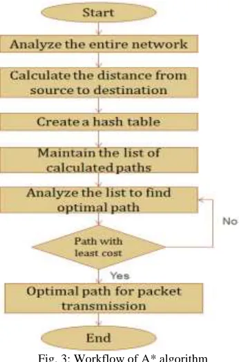
Fig. 3: Workflow of A* algorithm
A* uses a best-first search and detects a least-cost path from initial node to final node. As A* traverses the graph, it builds up a tree of partial paths. The leaves of this tree are stored in a priority queue that orders the leaf nodes by a cost function, which combines a heuristic estimate of the cost to reach a goal and the distance travelled from the initial node [3].
Specifically, the cost function is
f(n) = g(n) + h(n). Here,
g(n) is the known cost of getting from the initial node to any node; h(n) is a heuristic estimate of the cost to get from a node to goal node. A* maintains two sets of list,
Open Nodes examining. Closed Nodes examined.
Fig. 4: The directed path is the selected optimal path, which is part of the closed list.
Properties
A* has several useful properties.
A* is guaranteed to find a path from the start to the goal if there exists a path.
It is optimal if the search is always less than or equal to the actual cheapest path cost from n to the goal. No search method uses the same function to find an optimal path examines fewer nodes than A* [5].
VI. RESULT
Fig. 5: Node Deployment
Fig. 4: Anchor Nodes transfer packets to Object node
Fig. 9: Comparison graph of network lifetime
Fig. 10: Comparison graph of throughput
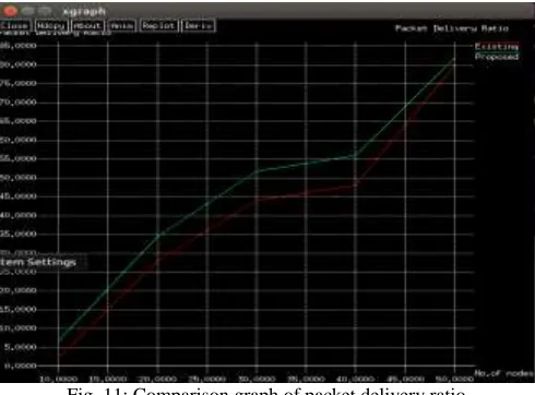
Fig. 11: Comparison graph of packet delivery ratio
VII.CONCLUSION AND FUTURE ENHANCEMENT
The proposed system reduces data transfer delay and increases the network lifetime by combining the localisation-synchronisation method and A* algorithm. It also improves the various QoS parameters such as throughput, end-to-end delay, packet delivery ratio and network lifetime.
REFERENCES
[1] Indian Journal of Emerging Electronics in Computer Communications Vol.2, Issue 1,2015, ISSN: 2393-8366 Scientist Link Publications “Diminishing
Propagation Delay within Underwater Sensor Networks Using JSL and ACO algorithm” Raja Vignesh.P, Sharmila R.N, Assistant Professor, Department of Information Technology, KCG college of Technology Chennai. India.
[2] “A Combined Localization-Synchronization Method for Underwater Communication” Z.Mousavi and R.Javidan / International Journal of Computer
Networks and Communications Security, December 2014, ISSN 2308-9830.
[3] IJCSNS International Journal of Computer Science and Network Security, VOL.11 No.1, January 2011, Manuscript revised January 20, 2011, “A*-based
Path-finding in Modern Computer Games”, Xiao Cui and HaoShi, School of Engineering and Science, Victoria University, Melbourne, Australia. International Journal of Advanced Science and Technology
[4] Volume 9, August, 2009, Simulation of Path Finding Algorithm – a Bird’s Eye PerspectiveR.Anbuselvi1 and R.S.Bhuvaneswaran, Lecturer in Computer
Science, Bishop Heber College, Trichy-17.Assist.Professor, Anna university, Chennai.
[5] I.J. Intelligent Systems and Applications, 2014, 08, 46-52 Published Online July 2014 in MECS, DOI: 10.5815/ijisa.2014.08.05 “Optimized Angular a Star
Algorithm for Global Path Search Based on Neighbour Node Evaluation” Ankit Bhadoria, Deptt. of Computer Science and Engineering, National Institute of Technology, Hamirpur, India, Ritesh Kumar Singh, Deptt. of Wireless Communication and Computing, Indian Institute Of Information Technology, Allahabad, India.
[6] Accuracy Studies for TDOA and TOA Localization, Regina Kaune, Dept. SDF, Fraunhofer, FKIE/University of Bonn, Wachtberg, Germany.
[7] Anchor Nodes Placement for Effective Passive Localization, Robert Akl, Karthik Pasupathy, Department of Computer Science and Engineering, University
of North Texas, Denton, Texas, USA, Mohamad Haidar, Department of Electrical Engineering, Ecole de Technologie Superieure, Canada.
[8] Node Synchronization for Minimizing Delay and Energy Consumption in Low-Power-Listening MAC Protocols Christophe J. Merlin and Wendi B.
Heinzelman Department of Electrical and Computer Engineering, University of Rochester, Rochester NY.
[9] http://www.aviatnetworks.com/solutions/advanced-technologies/network-synchronization.