Torque Ripple Reduction using Field Oriented
Control(FOC)-A Comparison Between BLDCM
and PMSM
Sumitra. K Prof. M. K. Giridharan
MCA Student MCA Student
Department of Computer Applications Department of Computer Applications IFET College of Engineering, Villupuram IFET College of Engineering, Villupuram
Abstract
AC motors have always been an area of interest in the field of electrical drives. With improvements in technology there is always a need of effective utilization of electrical power as well as the available resources. Nowadays the focus is given mainly on the efficiency of these drives with improvement in the performance of the motors used in the drives. Permanent magnet motors are classified as BLDC and PMSM among which Brushless DC Motor is one of the highly preferred AC motors used in various applications due to various advantages offered such as high efficiency, better speed versus torque characteristics. Although BLDC drives has several advantages it generates torque ripples which is a major concern in high precision applications especially in spacecrafts. Even though the torque generated is less when compared to BLDC motors, PMSM generates less torque ripples. Field oriented control of PMSM drives are becoming more popular especially in high precision applications. The main objective of this thesis is to make a comparison study between the FOC control of BLDC motor and PMSM in reducing torque ripples in reaction wheels used in satellites. FOC(Field Oriented Control) is used to achieve high performance control characteristics. FOC controlled AC motor drives provide better dynamic response and lesser torque ripples. The closed loop control of the BLDC Motor drive and PMSM drive using FOC is simulated in MATLAB SIMULINK.
Keywords: Permanent Magnet Alternating Current (PMAC) Motor, Brushless DC Motor (BLDCM), Permanent Magnet Synchronous Motor(PMSM), Field Oriented Control(FOC)
________________________________________________________________________________________________________
I.
I
NTRODUCTIONIn space flight analysis it is very important to know the position and motion of the satellite. Satellites are required to have more rapid rotational movement and agility than before in order to provide multi-target pointing and tracking capability. Reaction wheels are typical attitude control devices used in spacecraft which works on the principle of angular momentum[20].
The reaction wheels are basically flywheels which may be spun or braked down by an electric motor. Necessary torque required for pointing maneuver can be created by accelerating or decelerating the speed of motor. The required rotation can be created by changing the angular momentum. According to the law of conservation of momentum the body of the spacecraft to which the stator is connected start rotating in the opposite direction when the motor spins the wheel in one direction.
The rotation of the spacecraft can be stopped by braking down the wheel. In order to rotate the spacecraft back the wheel has to be spun backwards. Generally the moment of inertia of the reaction wheel is smaller than that of the spacecraft. The attitude can be tuned very precisely by spinning the wheel. Reaction wheel is often used in spacecrafts with cameras and other instruments which requires high precision [20]. Using three orthogonal wheels, attitude control by 3-axes can be achieved. In reaction wheels and momentum wheels, electric motor is used to drive high inertial wheel. Permanent magnet alternating current (PMAC) motors are commonly used for this purpose.
Permanent Magnet Alternating current (PMAC) motors are classified mainly into two types namely Permanent Magnet synchronous Motor (PMSM) and Brushless Direct Current Motor (BLDCM). Permanent magnet synchronous motor (PMSM) produces sinusoidal back EMF. The second type of PMAC which has trapezoidal back EMF is referred to as the Brushless DC (BLDC) motor [8]. The BLDC motor requires excitation with quasi-rectangular shaped currents.
In conventional DC motor current is switched by means of commutator and brushes whereas in BLDC motor electronic commutator is used thereby eliminating the need for brushes which reduces the wear and tear. Permanent Magnet AC(PMAC) motor drives are finding increased use in high performance applications where torque smoothness is essential. PMSM become popular in industry because of their advantages such as lightness, compactness and cost.
Hence the flux is only dependent on the field winding current. The torque can be controlled by the armature current if the flux is held constant. Because of this DC machines are said to have decoupled or independent control of torque and flux.
When compared to DC machines the stator and rotor fields are not orthogonal to each other in AC machines. The stator current is the only current that can be controlled. Field Oriented Control scheme is used to achieve the decoupled control of torque and flux by transforming the stator current quantities from stationary reference frame to torque and flux producing current components in rotating reference frame(d-q axis). It is more efficient than an AC induction motor because the production of the rotor flux is from a permanent magnet.
The application of field oriented control makes the performance of AC motors similar to that of DC motor. For this the quadrature axis current iq should be in quadrature with the rotor flux. Consequently id has to be along the rotor flux since id lags iq by 90º. If id is in the same direction as that of the rotor flux, the d axis stator flux adds to the rotor flux which results in the increase in the net air gap flux. On the other hand if id is negative then the stator d-axis flux is in opposite to that of the rotor flux resulting in a decrease in air gap flux. Field oriented control of PMSM produces lesser torque ripples.
FOC scheme not only decouples the torque and flux which makes faster response but also makes control task easy. FOC is carried out to control the space vector of magnetic flux, current and voltage of machines in order to attain the required torque. The aim of the FOC method is to control the magnetic field and torque by controlling the d and q components of the stator currents or consequently the fluxes.
II.
C
OMPARISON BETWEENBLDC
ANDPMSM
D
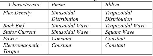
RIVEBased on the shape of the flux density distribution and stator current excitation, Permanent Magnet Synchronous motors are mainly classified into two categories namely permanent magnet synchronous motor (PMSM) and permanent magnet brushless DC motor(BLDCM). PMSM is also called as Permanent magnet AC motor (PMAC) which has got sinusoidal flux density, sinusoidal stator current variation and sinusoidal back EMF whereas in the case of BLDCM the flux density variation is rectangular, back emf is trapezoidal and current quasi square wave. Classification of the PMSM motors based on their characteristics are shown in Table 2.1.
Table - 1
Classification of Permanent Magnet AC Motor Characteristic Pmsm Bldcm Flux Density Sinusoidal
Distribution
Trapezoidal Distribution Back Emf Sinusoidal Wave Trapezoidal Wave Stator Current Sinusoidal Wave Square Wave Power Constant Constant Electromagnetic
Torque
Constant Constant
III.
B
LDC MOTOR TECHNOLOGY:
BLDC motors have three phase star connected stator windings and are placed 120 degree apart. Each of the winding is constructed with numerous interconnected coils, with one or more coils placed in the stator slots. The windings are distributed so as to produce trapezoidal back EMF. The rotor is made of permanent magnet with eight pole pairs with alternate North (N) and South (S) pole. Samarium Cobalt one of the rare earth magnet is used as permanent magnet. This magnet thus has high magnetic density per volume and enables using a smaller rotor and stator for the same torque [13]. These alloy magnets improve the size-to weight ratio and also give higher size-torque for the same size mosize-tor. In the case of Brushless DC mosize-tors ,there are no brushes on the rotor and the commutation is done electronically using inverter topology and hence they are normally referred to as electronically commutated motors.
In the case of BLDC motor it is required to sense the rotor position at each instant in order to determine when to change the direction of current thereby accomplishing electronic commutation. Rotor position is determined using either Hall effect sensors or optical encoder. Hall sensors are devices used for position estimation for the rotor which work on the principle of Hall Effect. The stator windings along with permanent magnets provided on the rotor generates a nearly uniform flux density in the air gap. BLDC motor has three Hall sensors inside the stator of the motor. A high or low signal is obtained when the rotor magnetic poles pass near the hall sensors indicating whether North pole or South pole is passing near the hall sensors. Thus proper commutation sequence can be determined based on the combination of Hall Sensors [12]. Hall sensors are embedded into the stationary part of the motor. Placement of hall sensors in the stator part is a difficult task as any misalignment will result in incorrect determination of rotor position. Thus the output of Hall Sensor reflects the rotation of the rotor.
significant torque ripple generated from the non-linearities in the commutation scheme, because only two motor windings carry current at a given time.
BLDC Motor is fed by a three phase voltage source inverter as shown in fig.1
Fig. 1: BLDC Motor Drive System
For each of the phases the equations on the stator side are given as
[ ] = [ ][ ] + [
]
[ ] +[ ] (1)
Where, Va, Vb, Vc are the motor phase voltage. L is the inductance of each of the phases. R is the resistance of each of the phases.
e
a, e
b, e
c are the back-emf of each of the phases.i
a, i
b,i
c are the phase current in each phases and M is the mutual inductance which is assumed to be zero .In the 3-phase BLDC motor, the instantaneous back-EMF is related to a function of rotor position which is given by the following equations.
= (2) = ( ) (3)
= ( ) (4) Where is back emf constant, θ is the electrical rotor angle and is the rotor speed. The generated electromagnetic torque is given by
= * + (5)
The electromagnetic torque is also related with the motor constant and product of the current with the electrical rotor position which is given by
= { } (6)
The equation of motion is given by
= J(
) + B (7)
Where J is the Moment of inertia of the motor and B is the coefficient of friction.
IV.
P
MSM TECHNOLOGY:
When compared to other AC motors, Permanent magnet synchronous motors(PMSM) have smaller size, better dynamic performance and very high efficiency. In the recent years there has been significant development in the field of power electronic devices and rare earth permanent magnetic materials like Ceramium cobalt which significantly improved efficiency of Permanent magnet motors. PMSM is widely used in high precision applications such as in national defense, and also in various day today applications.
PMSM is a rotating electrical machine which is provided with a three phase stator winding and permanent magnets in place of rotor. One of the magnetic fields is generated by the stator winding whereas the other one is created by the permanent magnet provided in the rotor in the case of PMSM [18]. The performance of the motor is highly dependent on the nature of the permanent magnet material used and therefore a proper understanding is required while selecting the material and in understanding the performance of PM motors.
Due to the interaction of the two magnetic fields an electromagnetic torque is produced which causes the motor to rotate in the case of PMSM. Sinusoidal commutation is used in the case of PMSM where all the three coils are excited at the same time. The torque produced will be smooth and has less ripples [5] since the current as well as the back emf are sinusoidal.
V.
F
IELD ORIENTED CONTROLThe main drawback of sinusoidal commutation is that the motor currents are controlled which are time variant and thus PI controllers have to operate on limited bandwidth. Hence using field oriented control the currents in a, b, c reference frame are transformed to d-q reference frame [1]. Thus controllers are not subjected from time variant currents and voltages and limitation of controller frequency response and phase shift on motor speed and torque is eliminated.
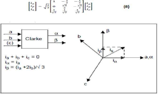
Using Field Oriented Control, current control is largely unaffected by speed of rotation of the motor. In the scheme of filed oriented control motor currents and voltages obtained from the motor are transformed into d-q reference frame. Measured currents from three stator phases which are now in the stator reference frame are converted into two phase using Clarke transformations which are further converted into the corresponding rotor reference frame using Park transformation [2]. The resultant current obtained is dc which is easier for the PI controllers to operate.
The obtained outputs from the PI controllers are transformed to inverse Park Transform to obtain the corresponding reference vector for the Space Vector PWM.
Fig. 2: Field Oriented Control Scheme
The advantages of Field Oriented Control are transformation of a complex and coupled AC model into a simple linear system , independent control of torque and flux, fast dynamic response , good transient and steady state performance ,high torque and low current at start up and high Efficiency.
Clarke Transformation Equation
Park Transformation Equation
Fig. 4: Park Transformation Inverse Park transformation equation
Fig. 5: Inverse Park Transformation
The Clarke transformation transforms the three phase (a, b, c) signals into α, β reference frame in the stator. In order to transform the signals to the rotor reference frame Park transformation is used so as to transform the signals into rotor reference frame (d-q) [6]. Inverse park transform converts the signals back to stator reference frame (d-q to α, β).
VI.
S
IMULATION RESULTSSimulation of Field oriented control of BLDC motor drive as well as PMSM drive is done in Matlab and the torque ripples generated are compared .Torque ripple is calculated using the formula, Torque ripple(%) = (Peak to peak torque/rated torque)*100.The simulation results for both motor drives are shown below.
The Model of field oriented control of the motor is shown in fig.6.
The stator current waveforms obtained for BLDC motor drive as well as PMSM drive using FOC is shown in fig.7 and fig.8.
Fig. 7: BLDC Motor Stator Current
Fig. 8: PMSM Stator Current
It is seen that in the case of PMSM the stator current is sinusoidal which will improve the torque smoothness .
The back emf generated by the BLDC and PMSM motor drives are shown respectively in figures Fig.9 and Fig.10. From this it is clear that the back emf produced by BLDCM is trapezoidal whereas back emf produced by PMSM is purely sinusoidal.
Fig. 9: Back emf generated by BLDCM
Fig. 10: Back emf generated by PMSM
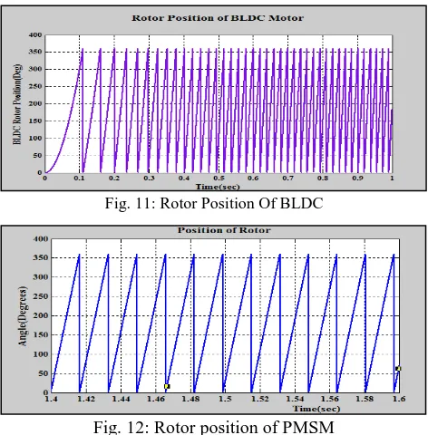
Fig. 11: Rotor Position Of BLDC
Fig. 12: Rotor position of PMSM
The torque waveform obtained indicates that torque ripples are reduced in the case of PMSM drive when compared to BLDC motor drive by using FOC.
Fig. 13: Torque generated by BLDC Motor
Fig. 14: Torque generated by PMSM
The speed of the BLDCM as well as PMSM attains steady state at 400 rps as shown in the below figures.
Fig. 16: PMSM Rotor Speed
The comparative results of the Field oriented control of BLDC and PMSM are shown in Table.2. Even though the torque developed is more in the case of BLDC when compared to PMSM for slight changes in the design parameters, the torque ripples are reduced significantly in the case of PMSM
Table - 2
Comparative Results of Torque Ripples
Field Oriented
Control Developed Torque
Torque Ripple Factor(%)
FOC with BLDC Drive 2.2-2.6 Nm > 30%
FOC with PMSM Drive
2 Nm < 5%
VII.
C
ONCLUSIONField oriented control of BLDC Motor Drive and PMSM Drive are both simulated in MATLAB and the results obtained are compared. The simulated results have shown that when compared to BLDC, the torque ripples are reduced to 5% in PMSM which makes it ideal for space applications.
VIII.
A
PPENDIXMachine Specifications: A.
R
EFERENCES[1] G.Jaya Baskaran,Prof.b.Adhavan,Dr.V.Jagannathan “Torque ripple Reduction in Permanent Magnet Synchronous Motor driven by Field Oriented Control
using Iterative Learning Control with Space Vector Pulse width modulation” 2013 International conference on Computer Communication and Informatics (ICCCI-2013) Jan-04-06,2013,Coimbature,India
[2] Adhavan.B, Kuppuswamy.A, Jayabaskaran.G,Jagannathan. V (2011) "Field oriented control of Permanent Magnet Synchronous Motor (PMSM) using
fuzzy logic controller"', Recent Advances in Intelligent Computational Systems (RAICS), IEEE, pp.587-592.
[3] V.Viswanathan,Dr.S.Jeevananthan,”A Novel Current Controlled Space Vector Modulation based Control Scheme for reducing Torque Ripple in Brushless
DC Drives”. International Journal of Computer Applications,28(2):25-31, August 2011.
[4] Bimal. K. Bose (2002), "Modem Power Electronics and AC- Drives", PHI Learning Private Limited.
[5] Favre E, Cardoletti L, Jufer M ( 1993),"Permanent Magnet Comprehensive Approach to Cogging Torque Suppression ", IEEE Transactions on Industry Applications, pp.1l41-1149.
[6] Gulez K, Adam A.A, Pastaci H ( 2008)," Torque Ripple& EMI Noise Minimization in PMSM Using Active Filter Topology & Field-Oriented Control".
IEEE Transactions on Industrial Electronics, vo1.55, no.l,pp.251-257.
[7] Jahns T.M, Soong W.L ( 1996)," Pulsating Torque Minimisation Techniques for Permanent Magnet AC Motor Drives - a review". IEEE Transactions on
Industrial Electronics, vol.43, no.2, pp.321-330.
[8] Qian.W,Panda S.K, Xu J.X, "Speed Ripple Minimization in Permanent Magnet Synchronous Motor Using Iterative Learning Control"'. IEEE Transactions
on Energy Conversion, vol.20, no.I, pp.53-61.
[9] Panda.S.K,X,Jian-Xin,Q.Weizhe,”Review of Torque Ripple Minimization in Permanent Magnet Synchronous Motor Drives” ,IEEE Transaction on
Electrical Engineering,July2008, pp.1-6
[10] John, J.P ,Kumar,S.S.,Jaya, B ”Space Vector Modulation based Field Oriented Control scheme for Brushless DC motors” Emerging Trends in Electrical
and Computer Technology (ICETECT), IEEE International Conference on 23-24 march 2011.
[11] Y. Liu, Z. Q. Zhu, and D. Howe, “Commutation-Torque-Ripple Minimization in Direct-Torque-Control PM Brushless DC Drives,” IEEE Trans. Ind.
Applicat, vol. 43, pp. 1012-1017, July/August 2007.
[12] Tao, G.L. Ma, Z.Y.Zhou, L.B., Li, Z.B. Modeling simulation and experiment of permanent magnet brushless DC motor drive” Universities Power
Engineering Conference, UPEC 2004. 39th International
[13] H.Lu, L.Zhang and W.Qu, “A new torque control method for torque ripple minimization of BLDC motors with un-ideal back EMF,”IEEE Trans. on Power
Electronics, Vol.21, No.6, pp.1762-1768, 2006.
[14] Samar, A Mara, Permatang,Saedin, P, Tajudin, A.I. Adni, N.”The implementation of Field Oriented Control for PMSM drive based on TMS320F2808 DSP
controller”. IEEE International Conference on Control System, Computing and Engineering (ICCSCE), 23-25 Nov. 2012.
[15] Madhusudan Singh, Archna Garg” Performance Evaluation of BLDC Motor with Conventional PI and Fuzzy Speed Controller” IEEE 2012.
[16] Yi Huang, Chunquan Li “Model and system simulation of Brushless DC motor bsed on SVPWM control” 2nd International Conference on Electronic &
Mechanical Engineering and Information Technology (EMEIT-2012).
[17] www.nptel.com (Lesson 20 FPGA, Version 2 EE IIT, Kharagpur).
[18] Thomas M. Jahns, and Wen L. Soong,” Pulsating Torque Minimization Techniques for Permanent Magnet AC Motor Drives-A Review” IEEE
[19] K.Giridharan,Gautham.R” FPGA Based Digital Controllers for BLDC Motors”International Journal of Engineering Research and Applications, Vol. 3, Issue 2, March- April 2013, pp.1615-1619.
[20] LAPPAS,V.J STEYN,W.H and UNDERWOOD, “Attitude control for small satellites using control moment gyros” Acta Astronautica, 2002,Vol .51,No.
1-9,pp. 110-111.
[21] Permanent Pragasen Pillay, Ramu Krishnan, “Modeling, Simulation, and Analysis of -Magnet motor Drives, Part II: The Brushless DC Motor Drive”, IEEE
transactions on Industry applications Vol. 25 No. 2 March/April 1989.
[22] T. Ktkioua, F. Melbody Tabar, R. Le Doeuff “A New Approach for the Field-Oriented Control of Brushless, Synchronous, Permanent Magnet Machines”.
[23] Vinod Kr Singh Patel, A.K.Pandey “Modeling and Simulation of Brushless DC Motor Using PWM Control Technique” International Journal of
Engineering Research and Applications (IJERA) ISSN: 2248-9622 Vol. 3, Issue 3, May- Jun 2013, pp. 612-620
[24] Joseph P John, Dr. S. Suresh Kumar, “Space Vector based Field Oriented Control Scheme for Brushless DC Motors”, Emerging Trends in Electrical and
Computer Technology (ICETECT), 2011 IEEE.
[25] M Kubeitari, A Alhusayn, and M Alnahar “Space Vector PWM Simulation for ThreePhase DC/AC inverter” World Academy of Science, Engineering and
Technology 702012.
[26] A.Alshehabi,M.H.Ferdowsi,andM.R.AlizadehPahlavani,”Improving theperformance of brushless dc motor using 6 digits from of SVPWM switching” basic