ISSN (e): 2250-3021, ISSN (p): 2278-8719
Vol. 09, Issue 12, December 2019, ||Series -II || PP 17-27
Reverse Engineering of a Bevel Gear
Habeeba Ahmed,
( 1 )Dr. Manzoor Hussain. M.
( 2 ) ( 1 ) Assistant Prof, Deccan College of Engineering & Technology( 2 ) Director of Admissions and Professor, JNTUH Received 10December 2019; Accepted 25 December 2019
ABSTRACT: Reverse Engineering is the process of obtaining a geometric CAD model from 3D scan points cloud which is acquired by scanning an existing part. 3D virtual models can be completely generated through reverse engineering. There are various applications of reverse engineering such as in manufacturing, industrial design, jewellery reproduction and design, development and inspection of parts, etc..,
A physical model is taken and scanned to get point cloud. This data is processed in different stages to finally get the CAD data. Dimensions, features, surfaces, etc.., can be reconstructed for the component using Reverse Engineering.
Keywords:
Reverse engineering, bevel gear, 3D scanning, point cloud, polygon model, NURBS surfaces.I.
INTRODUCTION
Reverse Engineering is the process of obtaining a geometric CAD model from 3D scanned point cloud data. Here, the component selected for the Reverse Engineering process is a bevel gear used in heavy vehicles such as buses and trucks. It was subjected to severe wear and tear and it had chipped off from a number of places. A detailed Reverse Engineering process was carried out for this bevel gear and finally the 3D CAD data was extracted with fine details.
A 3D Laser Scanner ( FARO Edge Scan Arm) was used for the acquisition of the point cloud data. The accuracy of this FARO probe + 35 um. It uses a 660 nm, laser and can scan upto 45120 points/sec.
The point cloud is then processed, optimised and edited to get the CAD model. The CAD model thus achieved can be used for various applications like RPT, for generation of conceptual models that can be used in CAM , CAE, etc..,
II.
METHODOLGY
In this work, the work piece chosen is a bevel gear used in heavy vehicles such buses and trucks. The chosen work piece had chipped off from different places on the gear teeth. In a highly worn-off condition the bevel gear was scanned and its CAD data was acquired.
The methodology adopted for the Reverse Engineering process of the bevel gear is as follows:
( Physical Object )
(Articulated Arm with a laser probe)
( Digital data 3D coordinates )
( Manual Alignment)
Bevel Gear
Data Acquisition
Point Cloud Data
( reduction of noise, removal of unwanted data points, sampling the data points and then identifying the primitives)
( by using the basic operations like rotate and move , merging and separation of point clouds, merging similar features like
faces, edges, points, holes , etc.., )
( Segementation which involves data points to be grouped into subsets to facilitate surface fitting . Segementation is based on surface geometries)
(involves construction of polygon models)
(This step involves cleaning of the polygon, removing errors
due to noise and refinement of the polygon mesh).
( primitives fitting, removal of holes, edge detection and
remeshing of the polygon )
(like rotate and move, Boolean operations , etc.., )
( Construction of cross- sections, curve fittings from points )
( Curve smoothing and cleaning, Curve degree conversion,
curve Re- direction, etc.., )
Data Optimization
Data Fitting
Image Processing
Polygon Generation
Polygon Optimization
Polygon Editing and
Control
Apply Basic
Operations
Curves Construction
Curve Modification and
Editing
Generation of surfaces from
the curves
.Points to CAD . Polygon to CAD . CAD to CAD
The complete and detailed Reverse Engineering process of the bevel gear is as follows.
Procedure: The physical object taken for the Reverse Engineering process is shown in the figure given below
Fig. 1. Bevel Gear
It has geometrical as well as free- form surfaces. From various views it has been checked in great detail. The chipped-off and worn –out surfaces can be clearly seen in the above figure.
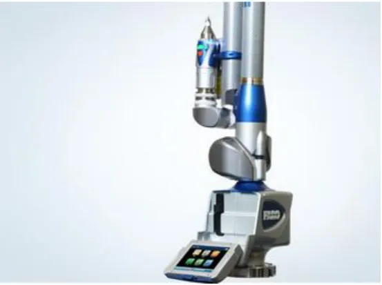
Data Acquisition: Initially, the bevel gear is cleaned properly and then scanned taking an Articulated Arm with a laser probe; the FAR0 Edge Scan Arm. It has an accuracy of + 35µm. It can scan 45000 points/sec or 750 points/line. It uses a laser and hard probe for acquisition of data points. The point clouds are obtained by moving the laser probe across the surface of the bevel gear.
Fig 2. FARO ARM PORTABLE CMM SCANNER
NURBS Surface Creation and
Controls
Through multiple scans , from different angles and views, the point clouds are obtained for the bevel gear. Around 70 scans were taken for the bevel gear from different positions and orientations. Shown below are some of the views of different point clouds. For each scan, the number of data points are also shown on the left bottom corner.
Fig 3. Scanned point cloud for the bevel gear
.
These multiple scans are taken from different positions and these scans are aligned according to the requirement in the next step.
Data Registration:
point clouds are aligned or merged so that the actual shape or geometry of the component is achieved. This aligned point cloud is used for the data optimization and segmentation.
III.
DATA OPTIMIZATION:
The point cloud obtained by scanning always has some points that are unwanted, some points which do not lie in the geometry of the component, etc.., Such data points are cleaned from the point cloud. Some errors due to noisy surfaces, very sharp edges, reflective surfaces are also very common while scanning. In this step, the point cloud is optimized by removal of unwanted data points, reduction of errors due to noise of sharp features, etc.., and then the primitive features of the bevel gear were identified. The different features like planes, lines, circles, arcs, free-form surfaces are identified and grouped into subsets. This process of grouping the point clouds into subsets is called Segmentation. In the bevel gear the different features identified were the lines, circles, fillet surfaces, free-form surfaces on the teeth of the bevel gear, etc..,
Data Fitting: This step involves simultaneous fitting of multiple curves and surfaces of the scanned point cloud. The curves and surfaces generated should create models that have sufficiently accurate tolerances and also reproduce the irregularities and symmetries required by the applications for which the CAD data may be used. Curves, edges, surfaces, etc.., are recognised in the previous step and formed as subsets. These subsets are merged by recognising similar features and applying on them basic operations like rotate and move. In presence of noisy data , it is cleaned properly so that the model produced , best describes the original one. The accuracy is also achieved accordingly.
Image Processing: In the previous step , geometric entities and features are recognised and detected. In image processing, these geometric entities and features are extracted from the images. Identified geometric features can be characterised by their size, position and also orientation.
There are three types of image processing techniques. The first is the edge detection method, second is the fitting of curves to regions of the image and the third is the template- based method.
The edge detection method can be done in two ways: 1. The edge-method, in which the edge points are extracted and then linked into edges and 2. The region method, through which uniform intensity regions are computed and the boundaries of these regions are extracted. The edges, boundaries and regions are recognised and then they are formed or grouped into segements.
Segmentation involves the cloud data to be grouped into subsets to facilitate surface fitting. Segmentation is based on the geometries of the surfaces of components. This segementation is of two types: 1. First order segementation and 2. Second order segementation.
The first order segementation is to identify or detect sharp edges, regions of high curvature and flat surface areas. The second order segementation subdivides the surface of the component according ti principal curvatures and it also serves as a foundation for the classification of simple algebraic surfaces. Following the creation of principal curvature-based segmentation, a major processing is performed. The three elements of post-processing are
( a ) Segement classification: which is based on the fitting procedure for basic surfaces such as planes, cylinders, cones and spheres.
( b ) Segement extension: based on the knowledge of the types of surfaces and their algebraic description, we join or extend the segements.
( c ) Iteration ( repetition of the procedure ) between the segement classification and segement extension. Mostly three iterations are sufficient to provide a satisfactory segementation. The figures below show the complete segementation.
Polygon Generation: Taking the segements into consideration, polygon models are generated in this step. The segements are aligned properly to achieve the best-fit alignment. After all the images are aligned, the final and complete point cloud of the bevel gear is achieved. This point cloud is processed and then a polygon mesh is generated. The different stages in this step includes:
Noise reduction – removing of scanned points from undesirable regions. Cleaning abnormal faces
Filter redundancy- uniformly reducing the number of points in a point cloud where the points are too close or over lapping each other.
Polygon Mesh – generation of the polygon and then mesh refinement
Fig4. Polygon with unrefined mesh.
After noise reduction and cleaning, the mesh is generated. For the bevel gear the number of triangles in the polygon mesh were 325468. The noise in the polygon phase is same as that in the points phase. The noise is reduced taking into consideration surface curvatures and features. Then the polygon surface is cleaned by removing dents, smoothen fillets, sharpen the edges, etc..,
Fig5. Polygon model of the Bevel Gear.
Then the polygon mesh is refined. At this stage the surface of the polygon model is added new vertices and then their coordinates are adjusted w.r.t. the existing vertices. This results in a much smoother surface and also an increase in the number of triangles of the polygon. The bevel gear had 375234 triangles after the mesh was refined properly.
Polygon Editing and Control: In this step a number of operations like filling holes, defeaturing, edge detection and sharpening control, primitives fitting, polygon editing and remeshing are carried out. The following figures show these different stages for the bevel gear.
For filling holes or gaps, a polygon structure is so selected that it matches the surrounding area. All the existing holes and gaps were filled properly so that the polygon surface area is completely covered.
Fig 6. Edge detection in the bevel gear.
Primitive Fitting:
In this step surface patches are fitted to 3-D points and the accuracy of fitting depends on some constraints that are used for approximation process. These constraints are expressed in terms of functional form of patches (ie.., planes, cylinders, cones, spheres, etc..,) or in terms of a measure of smoothness for splines, etc.., Fitting of a parameterized feature requires decisions as to which data points should be considered to lie on the feature and which lie outside the feature.
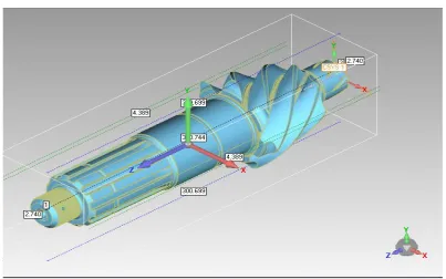
Polygon Editing and Remeshing: At this stage, the polygon generated is edited by remeshing. Edges or sharp features recognised, filling of holes, primitives fitting, all bring about changes in the polygon mesh. So, at this point, the polygon is again remeshed so that an accurate and high quality CAD model can be achieved. The following figures show the bevel gear before and after remeshing.
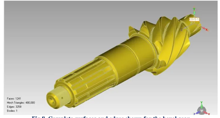
Fig 8. Complete surfaces and edges shown for the bevel gear
The polygon model is subjected to the most of the editing process. It includes changes in geometry and surface editing. As holes are filled, unwanted features removed, sharp features and edges recognised there is much change in the polygon and all these result in surface editing. After editing the surface of the polygon we see that the polygon mesh constitutes of best mesh triangles ( equilateral triangles ). The change or optimisation in the mesh at this stage results in the best polygon model.
The polygon model generated is now transformed into NURBS surface which is defined by a network of curves.
Curves Phase:
The network of define the NURBS surface. Basic CAD entities like lines, circles, arcs, rectangles can easily be created by manual fitting methods which are based on some reference points taken on the surfaces.
The curves phase consist of three important stages:
( i ) Cross- sectioning, which creates points or curves based on a plane that intersects with the model. ( ii ) 3-D curve fitting from points which allows a curve to be created from a set of data points. ( iii ) Curve modification, which can be done in any of the following ways
Changing the number of control points along a curve or redistributing the number of control points along a curve and this is called Curve reparmeterisation.
Changing the degree of the curve with a specified tolerance , called Curve degree conversion.
Curve smoothing and cleaning which involves smoothening a curve, cleaning and removing of unwanted control points.
Control point editing which includes modifying the control points manually
Point Generation in which a specified number of points from a curve with random or uniform distribution are created.
Curve redirection, transition and extension, which includes changing the direction of curves, stitching two curves to generate a new one and extend a curve to a point or distance with tangent or curvature continuity.
NURBS Surface Creation:
NURBS surfaces can be constructed from the CAD entities that are extracted in the curve phase or by using polygon meshes for the surface fitting.
The NURBS surface is created by laying down curves directly on the polygon model. The curves network created on the model forms the basis of the generation of surfaces. After the curves network is created the model is ready to generate the NURBS surface. In the following figures the NURBS surfaces can easily be seen.
IV.
RESULTS AND DISCUSSIONS:
The complete dimensions with details for the bevel gear are thus achieved and are shown below in the form of figures.
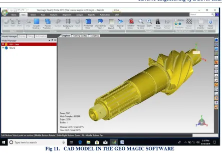
Fig 9. CAD MODEL OF THE BEVEL GEAR
Fig 11. CAD MODEL IN THE GEO MAGIC SOFTWARE
V. CONCLUSIONS
The bevel gear was scanned carefully and completely with a Faro Arm Scanner and the scanned point cloud processed in various stages to achieve the complete dimensional CAD data of the bevel gear. The CAD data for the bevel gear with minimum number of errors was achieved. Care was taken to see that in each step the amount of errors possible were minimum so that the CAD model can be used for any application. The different applications for which the CAD data can be used are RPT, additive manufacturing, 3D printing in medical and dental fields, etc.., By applying Reverse Engineering we can not only extract the dimensional details but also the drawings and documentation details. The CAD data also helps in product development cycle.
REFERENCES:
[1]. Urbanic, R.J., ElMaraghy, H.A., and ElMaraghy, W.H., “A reverse engineering methodology for rotary components from point cloud data,” International Journal of Advanced Manufacturing Technology, vol. 37, no. 11/12, pp. 1146-1167, 2008.
[2]. Raja, V., Fernandes, K.J., and SpringerLink (Online service), "Reverse engineering an industrial perspective," Springer series in advanced manufacturing, Springer, 2008,
[3]. Son, S., Park, H., and Lee, K.H., “Automated laser scanning system for reverse engineering and inspection,” International Journal of Machine Tools & Manufacture, vol. 42, no. 8, pp. 889-897, June, 2002
[4]. FARO®. "FARO provides a competitive all-in-one metrology solution," 15th July, 2015; http://www.faro.com/products/metrology/faro-scanarm/overview
[5]. A.W.L. Yao, “Applications of 3D scanning and reverse engineering techniques for quality control of
quick response products”, International
[6]. Journal of Advance Manufacturing Technology , Vol. 26, pp. 1284-1288,(2005).
[7]. S.Y. Park, J. Baek, J. Moon, “Hand-held 3D scanning based on coarse and fine registrationof multiple
range images”,Mach Applications, Vol. 22, pp. 563-579, (2011).
[8]. Gayatri D. Barai, Sunil S. Shete, Laukik P. Raut (2015): Design and development of a component by reverse engineering,IJRET: International Journal of Research in Engineering and Technology, eISSN: 2319-1163, pISSN:2321-7308
[9]. Kumar, A., Jain, P. K., Pathak, P. M. (2013): Reverse Engineering in Product Manufacturing: An Overview, DaamInternational Scientific Book, pp. 665–678, Chapter 39.
[11]. Langerak TR. Local parameterization of freeform shapes using freeform feature recognition. Computer-Aided Design 2010;42(8):682–92.
[12]. Benko, P., Kos, G., Andor, L. and Martin, R. R., Constrained Fitting in Reverse Engineering. Computer-Aided Geometric Design, Vol. 19, 2002, pp 173-205.
[13]. Benko, P. and Varady, T., Segmenting large point clouds in reverse engineering conventional engineering [14]. objects, In Proc. First Hungarian Conference on Computer Graphics and Geometry, pp 3-69, L.
Szirmay-Kalos and G. Renner (eds.), 2002.
[15]. Herbert J. Koelman (2010). Application of a photogrammetry-based system to measure and re-engineer ship hulls and ship parts: An industrial practices-based report, Computer-Aided Design, Vol. 42, (February, 2010), pp. 731-743
[16]. Tut V., A. Tulcan, C.Cosma, and Serban I. (2010). Application of CAD/CAM/FEA, Reverse Engineering And Rapid Prototyping In Manufacturing Industry, International Journal Of Mechanics, Vol. 4, No. 4, (2010), pp. 79-86