International Journal of Engineering
J o u r n a l H o m e p a g e : w w w . i j e . i rSemi-active Control of Building Structures using Variable Stiffness Device and
Fuzzy Logic
S. Pourzeynali* a, P. Jooeib
a.Department of Civil Engineering, Faculty of Engineering, The University of Guilan, Rasht, Iran. b.Department of Civil Engineering, The University of Guilan, Rasht, Iran
P A P E R I N F O
Paper history:
Received 21 November 2012 Received in revised form 06 March 2013 Accepted 18 April 2013
Keywords:
Semi-active Control Variable Stiffness Device (VSD) ON-OFF Algorithm
Fuzzy Logic Controller (FLC)
A B S T R A C T
Semi-active control devices, also called “Intelligent” control devices, constitute the positive aspects of both passive and active control devices. A semi-active control strategy is similar to the active control strategy, but this control device has been shown to be more energy-efficient than active devices. A particular type of semi-active control device, the Variable Stiffness Device (VSD), consists of a hydraulic cylinder with a normally closed solenoid control valve inserted in the tube connecting the two cylinder chambers. This paper emphasizes on the application of Semi-active Fuzzy Logic Controller (SFLC) of this system for getting the best results in the reduction of the building responses under earthquake excitations. For the numerical example, a 12-story building, located in the city of Rasht, Iran, is modeled as 3-D frame and the problem is solved in state space. The results obtained from the proposed control scheme (SFLC) are compared with those obtained from the ON-OFF control method. It is found that the SFLC is highly effective in reducing the responses of the example building than the ON-OFF algorithm. In this study, the optimal values of the fuzzy rule bases, membership functions, and the location of the control device are determined.
doi:10.5829/idosi.ije.2013.26.10a.07
1. INTRODUCTION 1
A critical aspect in the design of civil engineering structures is the reduction of response quantities such as velocities, deflections and forces induced by environmental dynamic loadings i.e., wind and earthquake. Structural control methods are the most recent strategies for this purpose, which can be classified as active, semi-active, passive, and hybrid control methods [1].
In the last three decades or so, the reduction of structural responses, caused by dynamic effects, has become the subject of many researches, and many structural control concepts have been implemented in practice [1].
Semi-active control systems were proposed as early as the 1920s when patents were issued for shock absorbers which utilized an elastically supported mass to activate hydraulic valving (no power required) or
*Corresponding Author Email: [email protected] (S. Pourzeynali)
utilized a solenoid valve for directing fluid flow (small amount of power required) [2]. Within the field of structural engineering, the first application of semi-active structural control for systems subjected to environmental loads appears return back to which have been proposed by Hrovat et al. [3] in 1983 [4]. Semi-active control systems are a class of Semi-active control systems for which the external energy requirements are orders of magnitude much smaller than typical active control systems, thus contributing to energy saving. In semi active control, the counteractive control forces are generated by reactive devices with variable damping and/or stiffness characteristics [5, 6]. These systems can operate during large earthquakes since they do not require much energy [7]. Semi-active control devices do not add mechanical energy to the structural system (including the system and control actuators), but control the states of the system such that the damping performance is maximized. Semi-active control devices are often viewed as controllable passive devices [8]. A semi-active control system may be defined as a system which typically requires a small external power source
for operation (e.g. a battery) and utilizes the motion of the structure itself to develop the control forces, the magnitude of which can be adjusted by the external power source [4].
So far several types of semi-active devices have been proposed and used in practice, from which the variable-orifice damper [9], variable stiffness device [10], semi-active friction damper [11], TMD system [12, 13], and the semi-active hydraulic damper installed in the Kajima Shizuoka Building in Shizuoka, Japan, can be mentioned. Other semi-active devices are the magneto- rheological dampers which are a particularly promising class because of their mechanical simplicity, low power requirements and high force capacity [14, 15]. In the present study, the performance of semi-active control system with variable stiffness is investigated using fuzzy logic.
2. SEMI-ACTIVE CONTROL DEVICE WITH VARIABLE STIFFNESS
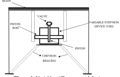
In the present study, semi-active control devices with variable stiffness are utilized to modify the stiffness and the natural vibration characteristics of the structure to which they are attached. Such systems have been investigated for seismic response control by Kobori et al. [10], Nemir et al. [16], Loh and Ma [17], Yamada and Kobori [18], Yang et al. [19] and Nagarajaiah [20]. The variable stiffness devices are engaged/ released so as to include or not include the stiffness of the bracing system of the structure, respectively. The device is composed of a balanced (double-acting piston rod) hydraulic cylinder with a normally closed solenoid control valve inserted in the tube connecting the two cylinder chambers. The solenoid valve can either be on or off, thus opening or closing the fluid flow path through the tube, respectively. When the valve is closed, the fluid cannot flow and effectively locks the beam to the braces below. In contrast, when the valve is open the fluid flows freely and disengages the beam/brace connection (Figure 1). The operation of each device consumes approx. 20 W of power. The system may be regarded as fail-safe in the sense that the interruption of power causes the variable stiffness devices to automatically engage which increasing the stiffness of the structure [4, 21].
In 1990, the application tests on the shaking table and research on models were made which show that these instruments have the initial preparation in use for the actual buildings. This is the underlying reason which is provided for using these instruments the same year on a real building. This system for the first time was used in industrial research institute Kajyma in Japan [22].
Different classical, robust and new control algorithms have been proposed for reducing the high-rise building responses [1, 23, 24].
Figure 1. Variable stiffness control device.
The most common ones are LQR, LQG, clipped control, bang-bang control, H2, H control, sliding
mode control, pole assignment, independent model space control (IMSC), and so on [25- 30]. However, recently, the fuzzy controller has been used for optimization of the control of civil engineering structures [28, 29, 31- 34]. The main advantages of the fuzzy controller can be summarized as [28]:
a) It is one of the few mathematical model free approaches to system identification and control which makes the system easier to design than developing an accurate mathematical model of the structural system needed for control system design. This can be done using human experience and expertise to implement the fuzzy controller.
b) It tolerates the uncertainties of the input data from wind or earthquake excitations and structural vibration sensors, consequently resulting in a controller system with a sufficient inherent robustness.
c) The fuzzy controller has the ability to handle the non-linear behavior of the structure caused by large displacements or material non-linearity and damage, although in the present study no non-linearity is considered.
d) The fuzzy controller can be adaptive by modifying its rules or membership functions and employing learning techniques.
3. ON-OFF CONTROL ALGORITHM
To explain this algorithm, first the equation of motion of a single degree of freedom (SDOF) system (Figure 2); consisted a variable stiffness device and subjected to earthquake excitation ̈ which is presented as [8]:
̈+ ̇+ + =− ̈ (1)
Figure 2. Idealized model of a single degree of freedom (SDOF) system.
= ( ) (2)
in which, ( ) is the stiffness of the control device. A control law was suggested to essentially switch the stiffness values through a hard switching or ON-OFF (relay) control. The control law is based on the position of the system with respect to the equilibrium state. The control law can be stated as [35]:
( ) = ̇ ≥0 (3a)
( ) = ̇ ≤0 (3b)
The control law can also be expressed in the following more compact form [35]:
( ) = .5 [ ( ) 1 + ( ) + ( ) 1− ( ) ]
≤ ≤
(4)
where, and are the maximum and
minimum stiffness of the control device, respectively; and sgn (a) is the sign function in which = ̇.
3. 1. Verification of the Control Algorithm In order to validate the control algorithm conducted in this study, the results of a simple SDOF system with the parameters of: m=50000 Kg, k=47000 kN/m, c=90 kN.sec/m, ksmax=15000 kN/m, and ksmin=2 kN/m are
compared with those given in reference [8] for the ON-OFF control algorithm and El Centro earthquake. The values of the obtained uncontrolled and controlled responses are 0.84 and 0.63 cm, respectively; while those of the ref. [8] are 0.83 and 0.59 cm. It is seen that difference between the values of controlled displacements in these two studies is less than 7%, which shows a good agreement between the results.
4. STRUCTURAL MODEL
The equation of motion of a high rise building structure subjected to a single support seismic excitation ̈ ( ), without any control system, can be written as [36]:
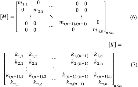
[ ]{ ̈} + [ ]{ ̇} + [ ]{ } =−[ ][ ]{ ̈ ( )} (5) in which, the × 1 vector {x} designates the relative displacements of each story to the ground; n is the number of degrees of freedom; the × 1 vector {r} is the influence vector representing the displacement of each degree of freedom resulting from static application of a unit ground displacement; and the × matrices of [M], [K] and [C] represent the structural mass, stiffness and damping matrices, respectively.
The building structure is modeled in ETABS software by considering the rigid diaphragm assumption. Therefore, each story will have three degrees of freedom. For jth floor, the degrees of freedom
at the center of mass are defined as follows: , translation in x and y directions, respectively, and rotation around the vertical axis. Assuming linear behavior of the structural components, structural stiffness and mass matrices are calculated and given in the following (Equations (6) and (7)).
[ ] =
⎣ ⎢ ⎢ ⎢
⎡ 0, 0
, ⋯
0 0 0 0
⋮ ⋱ ⋮
0 0
0 0 ⋯ ( ),( ) 0
0 , ⎦
⎥ ⎥ ⎥ ⎤
×
(6)
[ ] =
⎣ ⎢ ⎢ ⎢ ⎢
⎡ , ,
, , ⋯
,( ) , ,( ) ,
⋮ ⋱ ⋮
( ), ( ),
, , ⋯
( ),( ) ( ), ,( ) , ⎦⎥
⎥ ⎥ ⎥ ⎤
× (7)
in which, , is the floor mass or mass moment of inertia, and , is the force produce in i degree of freedom due to static unit displacement in j degree of freedom.
The structural damping matrix [C] is assumed to be proportional to the mass and stiffness matrices as [36]:
[ ] = [ ] + [ ], = ,
=
(8)
in which, and are the proportional coefficients; and are the structural modal frequencies of modes
i and j, respectively; and is the structural damping ratio for the two modes (In this research = 5% ).
5. FUZZY LOGIC CONTROLLER (FLC)
mathematics is that the fuzzy set theory allows objects to have any degrees of membership (between 0% and 100%) within a set, while traditional mathematics requires objects to have either 0% or 100% membership. As a result, fuzzy set theory involves terminology that is different from that of traditional mathematics [29]. Fuzzy logic enables the use of linguistic directions as a basis for control, generally very capable of handling systems. The most widely used fuzzy control inference is the “if–then” rule, which can be written as follows when two input data are used in their antecedent parts [33]:
∶ = , = ℎ = (9)
The basic structure of a typical FLC is illustrated in Figure 3, in which the components are defined as follows [1]:
•Fuzzifier: In this unit, the measured inputs in the control process, which may be in the form of crisp values, would be converted into fuzzy linguistic values using fuzzy reasoning mechanism.
•Fuzzy rules: This is a collection of the expert control rules needed to achieve the control goal.
•Fuzzy interference engine: This unit is the fuzzy reasoning mechanism, which performs various fuzzy logic operations to infer the control action for a given fuzzy input.
•Defuzzifier: The inferred fuzzy control action is converted into the required crisp control value in this unit. The design of a fuzzy controller involves decisions about a number of important design parameters that should be determined before the actual control starts. These parameters are the fuzzy sets in the rules, the rules themselves, scaling factors in input and output, inference methods, and defuzzification procedures [1].
6. THE EQUATION OF MOTION OF THE STRUCTURE WITH VARIABLE STIFFNESS DEVICE
To write the equation of motion in controlled state, a series of changes should be made in the original equation of motion in the uncontrolled case (Equation (5)).
Figure 3. FLC components.
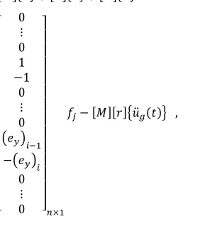
For this purpose, the effect of the control device is considered as a force in the right hand side of the uncontrolled equation of the building to get the equation of motion in controlled state when only one control device is considered in the jth degree of freedom
(Equation (10)) [38, 39]: [ ]{ ̈} + [ ]{ ̇} + [ ]{ } =
⎣ ⎢ ⎢ ⎢ ⎢ ⎢ ⎢ ⎢ ⎢ ⎢ ⎢ ⎢ ⎢ ⎡ 0⋮
0 1
−1 0
⋮ 0
− 0 ⋮ 0 ⎦⎥
⎥ ⎥ ⎥ ⎥ ⎥ ⎥ ⎥ ⎥ ⎥ ⎥ ⎥ ⎤
×
−[ ][ ] ̈ ( ) ,
= ( ) ∆
(10)
where, ∆ is the relative displacement of the floors that control device installed.
By generalizing the above equation for m variable stiffness device installed in two directions of x and y for a building structure with n degrees of freedom can be written as follows:
[ ] × { ̈} × + [ ] × { ̇} × +[ ] × { } × = [ ] × { } × −[ ] × [ ] × { ̈ ( )} ×
(11)
where, is the control force of the m variable stiffness device which is a function of time according the response of structure jth element, and can be
calculated by the Equation (10). [D] is a × transfer matrix. In general, matrix [D] can be calculated as given in Equation (12) in which p and q are the number of variable stiffness devices along the x and y directions, respectively.
7. APPLICATION OF FUZZY LOGIC TO EVALUATE THE VARIABLE STIFFNESS OF CONTROL DEVICE
Performance of fuzzy controller depends on the design of its different characteristics such as range of input data, selection of the membership functions and fuzzy rules. Particularly, logical selection of the fuzzy rules at different levels of structural responses is very important. Fuzzy controller receives input data at any time from the structural responses, and then determines the output data using fuzzy inference engine and the table of fuzzy rules. Since stiffness is the major factor in changing the amount of control force in variable stiffness device, fuzzy controller should determine the required stiffness to reduce the structural responses. This process is shown in Figure 4.
In this study, the Mamdani inference engine is used in fuzzy controller. Mamdani inference engine maps the fuzzy input sets to the output sets with fuzzy rules. Fuzzy controller uses scaled data directly from the model of the building. Then, these data are converted into linguistic or fuzzy membership functions through the fuzzification process. The controller is designed based on two-input variables (displacement and velocity of the building’s stories); and three-input variables (displacement, velocity and acceleration of the building’s stories). To evaluate the performance of the control system and obtain the best results from the fuzzy controller, different membership functions and rule bases are being used, which are explained in the following:
7. 1. Normalized Membership Functions for Two and Three-input Systems In fuzzy control of the dynamic systems, it is common to scale the input variable to put them between [-1, 1]. For this purpose, the factors , and are used to convert the inputs into the interval [-1, 1]. These factors are initially calculated according to equations proposed by Yager and Filev [40] to normalize the universes of discourse to [-1, 1] as given in the following:
Figure 4. Determination of the variable stiffness through the
FLC process.
=
, = = (13)
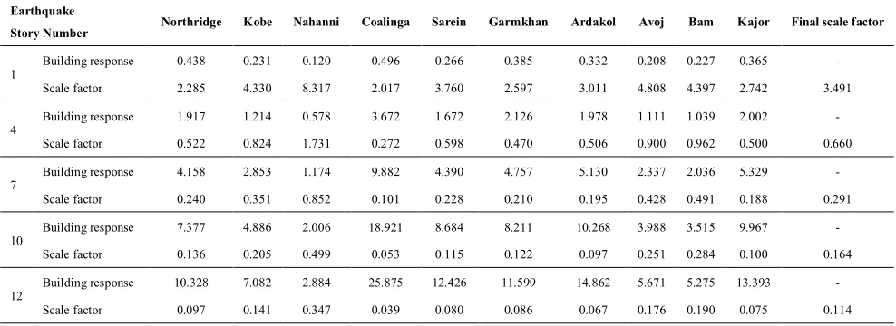
where, , and are the maximum displacement, velocity and acceleration of the building, respectively on the story level at which the control device is installed. The maximum displacement ( ) is estimated based on the uncontrolled responses of the building to the selected earthquakes.
For this purpose, first was calculated using the maximum responses of the building on the story level at which the control device is installed for each of the scaled earthquakes, and averaged to obtain the final values for each story level as show in Table 1. In a similar way, the scale factors are derived for the input velocity and acceleration of each story.
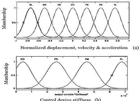
In this research, for both input and output data, three different membership functions namely: Triangular, Trapezoidal, and Gaussian (Figures 5-7) are used.
Figure 5. Triangular membership functions; a) for input
variables (displacement, velocity and acceleration); b) for output variable (control device stiffness).
Figure 6. Gaussian membership functions; a) for input
TABLE 1. Scale factor for displacement input for the fuzzy controller Earthquake
Story Number Northridge Kobe Nahanni Coalinga Sarein Garmkhan Ardakol Avoj Bam Kajor Final scale factor
1 Building response 0.438 0.231 0.120 0.496 0.266 0.385 0.332 0.208 0.227 0.365 - Scale factor 2.285 4.330 8.317 2.017 3.760 2.597 3.011 4.808 4.397 2.742 3.491
4 Building response 1.917 1.214 0.578 3.672 1.672 2.126 1.978 1.111 1.039 2.002 - Scale factor 0.522 0.824 1.731 0.272 0.598 0.470 0.506 0.900 0.962 0.500 0.660
7 Building response 4.158 2.853 1.174 9.882 4.390 4.757 5.130 2.337 2.036 5.329 - Scale factor 0.240 0.351 0.852 0.101 0.228 0.210 0.195 0.428 0.491 0.188 0.291
10 Building response 7.377 4.886 2.006 18.921 8.684 8.211 10.268 3.988 3.515 9.967 - Scale factor 0.136 0.205 0.499 0.053 0.115 0.122 0.097 0.251 0.284 0.100 0.164
12 Building response 10.328 7.082 2.884 25.875 12.426 11.599 14.862 5.671 5.275 13.393 - Scale factor 0.097 0.141 0.347 0.039 0.080 0.086 0.067 0.176 0.190 0.075 0.114
Figure 7. Trapezoidal membership functions; a) for input
variables (displacement, velocity and acceleration); b) for output variable (control device stiffness).
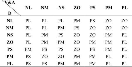
7. 2. Fuzzy Rule Bases The abbreviations used for fuzzy input and output membership functions to define the fuzzy space are: NL = Negative and Large; NM = Negative and Medium; NS = Negative and Small; ZO = Zero; PS = Positive and Small; PM = Positive and Medium; PL = Positive and Large. On this basis, different rule bases are defined which are given in the following:
7. 2. 1. Fuzzy Controller Rule Basses for Two-input Variables One of the most important parts of the FLC is the table of rule bases. In order to get the optimal performance of the FLC, the members of this table should be built based on a logical judgment. For this purpose, it is noted that when the seismic response of the structure increases, then the control force
produced by the variable stiffness device must be increased in order to reduce the seismic effect on the structure. The fuzzy rule bases made on this basis are providing in Tables 2-4 (called case 1 to case 3). It is noted that, in this part of the study, the displacement and velocity of the building story at which the control system is installed, are considered as the inputs to the FLC, and the stiffness of control device is the output of the FLC.
TABLE 2.Two-input variables rule bases in fuzzy controller
(case 1). PL PM PS ZO NS NM NL V D ZO ZO ZO PM PL PL PL NL ZO ZO ZO PS PL PL PL NM PM PS ZO ZO PL PL PL NS PL PM PS ZO PS PM PL ZO PL PL PL ZO ZO PS PM PS PL PL PL PS ZO ZO ZO PM PL PL PL PM ZO ZO ZO PL
TABLE 3. Two-input variables rule bases in fuzzy controller
TABLE 4. Two-input variable srule bases in fuzzy controller (case 3). PL PM PS ZO NS NM NL V D ZO - - PS PM PL PL NL ZO ZO PS PM PM PL PL NM PM PS - - PS PM PM NS PM PM - - - PM PM ZO PL PL PM - PS PM PM PS PL PM PS PS - PS PM PM PL PL PL PM PS PS ZO PL
7. 2. 2. Fuzzy Controller Rule Basses for Three-Input Variables In this part of the study, three inputs namely: displacement, velocity and acceleration of the building stories, at which the control device is installed, are considered as the inputs to the FLC. However, the output of the FLC is the same variable stiffness of the control device. Here, similar to the section (7. 2. 1), three sets of rule bases are also chosen and shown in Tables 5-7 (called cases 4 to 6). It is noted that, here in order to reduce the time of analysis, the fuzzy spaces of the velocity and acceleration are divided in the same manner.
TABLE 5. Three-input variables rule bases in fuzzy controller
(case 4). PL PM PS ZO NS NM NL V&A D ZO ZO PS PM PM PL PL NL ZO ZO PS PS PM PM PL NM PS PS ZO ZO PS PM PL NS PL PM PS ZO PS PM PM ZO PL PM PS ZO ZO PS PS PS PL PM PS ZO ZO PS PS PM PL PM PM PS ZO ZO ZO PL
TABLE 6. Three-input variables rule bases in fuzzy controller
(case 5). PL PM PS ZO NS NM NL V&A D ZO ZO PS PM PL PL PL NL ZO ZO ZO PS PM PL PL NM PL PM ZO ZO PS PM PL NS PL PM PM ZO PM PM PL ZO PL PM PS ZO PS PS PM PS PL PL PM PM ZO ZO PS PM PL PL PM PM PM PS PS PL
TABLE 7. Three-input variables rule bases in fuzzy controller
(case 6). PL PM PS ZO NS NM NL V&A D ZO ZO ZO PS PM PL PL NL ZO ZO PS PM PM PL PL NM PM PS ZO PS PS PM PM NS PM PM PS ZO PS PM PM ZO PL PL PM PS PS PM PM PS PL PM PS ZO PS PS PM PM PL PL PL PM PS PS ZO PL
8. NUMERICAL STUDY
In order to investigate the performance of the proposed control strategy in reducing the structural responses under earthquake loadings, a 12-story building, located in city of Rasht, Iran, is chosen as an example problem. The Building plan dimensions are 31.9×21 meters, and simple frames with moderate ductility and chevron centrically braced frames are consider as its lateral force resisting system in both directions. The locations at which the control devices are installed are shown in Figure 8. In the present study, the optimal placement of this control device is not studied. It is the goal of future investigations.
Figure 8. The locations of control devices on the buildings
To investigate the effectiveness of the proposed control system for different disturbances, the horizontal components of ten different seismic motions shown in Table 8 are used in the simulations. In order to analyze the example building under application of these accelerograms, they are corrected for base-line deviations and band-pass filtered for unwanted noises based on IBC 2006 provisions [41].
In this step of the study, in other to select the optimal membership function and rule base for two-input system explained earlier, first the example building is analyzed under the application of the above mentioned accelerograms. Then, the uncontrolled and controlled response quantities of the building stories using fuzzy
logic and the rule bases given in Table 2 (case 1) for three different membership functions (Triangular, Trapezoidal and Gaussian) while keeping the other fuzzy controller parameters constant, are calculated. The average results of maximum controlled displacement and acceleration responses of the example building stories calculated above are compared with the corresponding uncontrolled ones in Tables 9 and 10. It can be seen from the results that, triangular membership function has good performance compared to the other two membership functions. Therefore, rest of the study is performed by considering Triangular member-ship function.
TABLE 8. Informationof the used earthquakes
1Uncorrected Peak Ground Acceleration (UPGA) 2National Earthquake Information Center 3Building and Housing Research Center 4United States Geological Survey 5Center Weather Bureau
TABLE 9. Comparison of the effectiveness of selected membership functionsins in reducing the building stories displacement
response (for two-input variables, fuzzy algorithms and rule-bases of Table 2)
Building floor Maximum uncontrolled displacement (cm) Response reduction ratio (%)
Triangular MF Trapezoidal MF Gaussian MF
1 0.307 48.77 48.28 42.05
2 0.689 47.50 46.78 41.26
3 1.165 45.17 44.63 40.10
4 1.731 43.26 42.83 38.78
5 2.360 41.98 41.65 37.85
6 3.208 42.43 42.26 38.67
7 4.205 43.05 42.99 39.62
8 5.287 43.42 43.42 40.30
9 6.450 43.41 43.50 40.79
10 7.788 43.87 44.06 41.71
11 9.412 44.97 45.20 43.21
12 10.950 45.68 45.93 44.25
Reference Duration (s)
UPGA (g)1
Magnitude (Ms) Stations of accelerograms
Date Earthquake
No. of accelerograms
NEIC2
42.23 0.16
6.1 Astara
1997 Sarein-Iran
1
NEIC 14.905
0.08 6.1
Gonbadkavos 1997
Garmkhan-Iran
2
NEIC 92.155
0.13 7.7
Gonabad 1997
Ardakol-Iran
3
NEIC 26.875
- 6.5
Gilvan 2002
Avoj-Iran
4
NEIC 83.195
0.799 6.7
Mahan 2002
Bam-Iran
5
BHRC3
78.075 -
6.2 Kiashahr
2004 Kajor-Iran
6
USGS4
39.99 1.083
6.0 Transmitter Hill
1983 Coalinga- USA
7
CWB5
40.95 .0821
6.9 Abeno
1995 Kobe- Japan
8
USGS 20.56
1.096 6.9
Sitel 1985
Nahanni- Canada
9
USGS 34.98
0.128 6.7
Montebello 1994
Northridge- USA
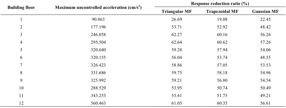
TABLE 10. Comparison of the effectiveness of selected membership functions in reducing the building stories acceleration response (for two-input variables, fuzzy algorithms and rule-bases of Table 2)
Building floor Maximum uncontrolled acceleration (cm/s2) Response reduction ratio (%)
Triangular MF Trapezoidal MF Gaussian MF
1 90.863 26.69 19.08 22.45
2 177.196 53.71 52.92 48.42
3 246.058 62.27 60.16 56.26
4 295.504 62.64 60.62 57.26
5 320.640 59.28 57.94 54.06
6 320.155 56.04 53.74 48.55
7 326.423 58.86 57.05 53.53
8 331.686 59.75 58.18 54.96
9 325.992 59.21 56.80 54.54
10 288.529 53.95 50.74 50.49
11 343.253 53.41 51.75 49.21
12 560.463 61.05 60.35 56.61
TABLE 11. Comparison of the effectiveness of the different tow-input variable rule bases used in this study.
Building floor Maximum uncontrolled displacement (cm) Response reduction ratio (%)
Table 2 (case1) Table 3 (case2) Table 4(case3)
1 0.307 48.77 53.81 51.74
2 0.689 47.50 52.32 50.73
3 1.165 45.17 48.87 47.82
4 1.731 43.26 46.17 45.17
5 2.360 41.98 44.10 43.13
6 3.208 42.43 43.74 42.91
7 4.205 43.05 43.67 42.92
8 5.287 43.42 43.41 42.68
9 6.450 43.41 43.01 42.25
10 7.788 43.87 43.09 42.38
11 9.412 44.97 43.80 43.17
12 10.950 45.68 44.26 43.65
TABLE 12. Comparison of the effectiveness of the different tow-input variable rule bases used in this study.
Building floor Maximum uncontrolled acceleration (cm/s2) Response reduction ratio (%)
Table 2 (case1) Table 3 (case2) Table 4 (case3)
1 90.863 26.69 41.73 35.56
2 177.196 53.71 62.90 59.91
3 246.058 62.27 68.21 65.24
4 295.504 62.64 67.11 64.35
5 320.640 59.28 64.04 60.83
6 320.155 56.04 61.77 57.08
7 326.423 58.86 63.77 60.72
8 331.686 59.75 65.35 62.76
9 325.992 59.21 63.07 58.02
10 288.529 53.95 55.83 52.97
11 343.253 53.41 53.00 52.83
TABLE 13. Comparison of the effectiveness of the different three-input variable rule bases used in this study.
Building floor Maximum uncontrolled displacement (cm) Response reduction ratio (%)
Table 5 (case 4) Table 6 (case 5) Table 7 (case 6)
1 0.307 60.72 58.52 58.20
2 0.689 59.37 57.14 56.81
3 1.165 55.99 53.31 53.30
4 1.731 53.60 50.58 50.57
5 2.360 51.85 48.63 48.64
6 3.208 51.56 48.31 48.25
7 4.205 51.59 48.30 48.22
8 5.287 51.41 48.04 47.96
9 6.450 51.12 47.70 47.60
10 7.788 51.22 47.74 47.62
11 9.412 51.76 48.24 48.03
12 10.950 52.07 48.62 48.43
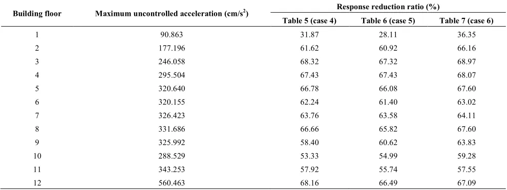
TABLE 14. Comparison of the effectiveness of the different three-input variable rule bases used in this study.
Building floor Maximum uncontrolled acceleration (cm/s2) Response reduction ratio (%)
Table 5 (case 4) Table 6 (case 5) Table 7 (case 6)
1 90.863 31.87 28.11 36.35
2 177.196 61.62 60.92 66.16
3 246.058 68.32 67.32 68.97
4 295.504 67.43 67.43 68.07
5 320.640 66.78 66.08 67.60
6 320.155 62.24 61.40 63.02
7 326.423 63.76 63.58 64.11
8 331.686 66.66 65.82 67.60
9 325.992 58.40 60.62 63.83
10 288.529 53.33 54.99 59.28
11 343.253 57.92 55.74 57.55
12 560.463 68.16 66.49 67.09
Now, by choosing the triangular membership function, the building is analyzed. The average results of maximum controlled displacement and acceleration responses of the example building stories due to the aforementioned ten accelerograms for two-input variable system and the rule bases given in Tables 2-4 are calculated and compared with the corresponding uncontrolled ones in Tables 11 and 12. Here, by comparing the results of the tables, it is also seen that performance of the rule bases given in Table 2 is the best.
After performing the FLC procedure for two-input variables which explained above, herein the same building is being analyzed for three-input variables and the selected accelerograms of Table 8 and Triangular membership function in order to investigate the effectiveness of fuzzy rule bases are given in Tables 5-7. The average results of the maximum controlled
displacement and acceleration responses of the example building stories calculated above are compared with the corresponding uncontrolled ones in Tables 13 and 14. It can be seen from the results that, the rule bases given in Table 5 have good performance compared to the other rule bases.
uncontrolled ones. As well, the control force and stiffness of variable stiffness device (VSD) are shown in Figures 10 and 11 for Nahanni accelerogram and for the
semi-active ON-OFF and SFLC algorithms,
respectively. It is seen from the Figure 9 that the SFLC system with three-input variables significantly reduces the building top story responses.
(a)
(b)
Figure 9. Comparison of the controlled displacement and
acceleration of the example building top story calculated by the ON-OFF, and SFLC for two and three-input systems with the uncontrolled ones for Nahanni earthquake accelerogram.
(a)
(b)
Figure 10. Variation of VSD control force and stiffness in the
first floor of the building in ON-OFF algorithm for Nahanni earthquake accelerogram.
(a)
(b)
Figure 11. Variation of VSD control force and stiffness in the
first floor of the building in SFLC algorithm for Nahanni earthquake accelerogram.
variables are capable of reducing the maximum displacement of the building top story to about 39.55%, 45.68% and 52.07% of the uncontrolled response, respectively. As well as, they are capable of reducing the maximum acceleration of the building top story to about 32.51%, 61.05% and 68.16% of the uncontrolled response, respectively. Therefore, on average the designed SFLC with three-input variables system is more effective than the other.
9. CONCLUSIONS
This paper focuses on the application of semi-active ON-OFF algorithm and semi-active fuzzy logic
controller (SFLC) for reducing of the high rise building responses subjected to earthquake excitations using the variable stiffness device (VSD) control system. Two FLC systems are designed for calculating the stiffness in a VSD control system in order to get the maximum reduction in displacement and acceleration response quantities of the building stories. In the design of the SFLC system, the building stories displacement and velocity responses in two-input variables system; and displacement, velocity and acceleration responses in three-input variables system are considered as the input variables to the SFLC. For the numerical study, a 12-story building is chosen and modeled as a 3-D frame and the problem is solved in state space.
TABLE 15. Comparison of the effectiveness of different controller systems used in this study in reducing the average maximum
displacement.
Building floor Maximum uncontrolled displacement (cm) Response reduction ratio (%)
ON-OFF SFLC (2 Inputs) SFLC (3 Inputs)
1 0.307 32.35 48.77 60.72
2 0.689 32.73 47.50 59.37
3 1.165 31.83 45.17 55.99
4 1.731 30.47 43.26 53.60
5 2.360 29.34 41.98 51.85
6 3.208 30.43 42.43 51.56
7 4.205 32.34 43.05 51.59
8 5.287 33.82 43.42 51.41
9 6.450 34.56 43.41 51.12
10 7.788 36.41 43.87 51.22
11 9.412 38.74 44.97 51.76
12 10.950 39.55 45.68 52.07
TABLE 16. Comparison of the effectiveness of different controller systems used in this study in reducing the average maximum
acceleration.
Building floor Maximum uncontrolled acceleration (cm/s2) Response reduction ratio (%)
ON-OFF SFLC (2 Inputs) SFLC (3 Inputs)
1 90.863 -151.23 26.69 31.87
2 177.196 -18.20 53.71 61.62
3 246.058 -7.24 62.27 68.32
4 295.504 -0.74 62.64 67.43
5 320.640 17.29 59.28 66.78
6 320.155 8.84 56.04 62.24
7 326.423 13.99 58.86 63.76
8 331.686 23.22 59.75 66.66
9 325.992 -16.00 59.21 58.40
10 288.529 -29.57 53.95 53.33
11 343.253 -3.64 53.41 57.92
From the numerical results of the study, it is found that: 1. Performance of the SFLC system in reducing the
building responses is better than that of the ON-OFF system.
2. In view of the building response reduction, the SFLC with three-input variables system is more effective than the two-input system.
3. In present study, the triangular membership function is found as the optimal membership function in compression with the Trapezoidal and Gaussian functions.
4. Moreover, in this study, the optimal rule bases are suggested for semi-active fuzzy controller.
5. It is shown that the designed SFLC system with three-input variables system is capable to reduce the example building top story displacement and acceleration to about 52% and 68%, respectively.
[1-41]
10. REFERENCES
1. Pourzeynali, S., Lavasani, H. and Modarayi, A., "Active control of high rise building structures using fuzzy logic and genetic algorithms", Engineering Structures, Vol. 29, No. 3, (2007), 346-357.
2. Crosby, M., Harwood, R. and Karnopp, D., "Vibration control using semi-active force generators", Transactions of the ASME, Paper, (1974).
3. Hrovat, D., Barak, P. and Rabins, M., "Semi-active versus passive or active tuned mass dampers for structural control",
Journal of Engineering Mechanics, Vol. 109, No. 3, (1983), 691-705.
4. Symans, D. M. and Constantinou, C. M., "Semi-active control systems for seismic protection of structures: A state-of-the-art review", Engineering Structures, Vol. 21, (1999), 469-487. 5. Onoda, J., Endot, T., Tamaoki, H. and Watanabe, N., "Vibration
suppression by variable-stiffness members", AIAA journal, Vol. 29, No. 6, (1991), 977-983.
6. Shen, Y., Golnaraghi, M. and Heppler, G., "Semi-active vibration control schemes for suspension systems using magnetorheological dampers", Journal of Vibration and Control, Vol. 12, No. 1, (2006), 3-24.
7. Lai, J. and Wang, K., "Parametric control of structural vibrations via adaptable stiffness dynamic absorbers", Journal of Vibration and Acoustics, Vol. 118, No. 1, (1996), 41-47. 8. Aldemir, U. and Bakioglu, M., "Semi-active control of
earthquake-excited structures", Turkish Journal of Engineering and Environmental Sciences, Vol. 24, (2000), 237- 246. 9. Patten, W. N., Sack, R. L. and He, Q., "Controlled semiactive
hydraulic vibration absorber for bridges", Journal of Structural Engineering, Vol. 122, No. 2, (1996), 187-192.
10. Kobori, T., Takahashi, M., Nasu, T., Niwa, N. and Ogasawara, K., "Seismic response controlled structure with active variable stiffness system", Earthquake engineering & Structural Dynamics, Vol. 22, No. 11, (1993), 925-941.
11. Lu, L.-Y., "Semi-active modal control for seismic structures with variable friction dampers", Engineering Structures, Vol. 26, No. 4, (2004), 437-454.
12. Pourzeynali, S. and Esteki, S., "Optimization of the tmd parameters to suppress the vertical vibrations of suspension bridges subjected to earthquake excitations", Iranian
International Journal of Engineering, Transaction B: Application, Vol. 22, No. 1, (2009), 23-34.
13. Golafshani, A. and Gholizad, A., "Passive vibration control for fatigue damage mitigation in steel jacket platforms",
International Journal of Engineering-Transactions B: Applications, Vol. 21, No. 4, (2008), 313.
14. Pourzeynali, S., Malekzadeh, M. and Esmaeilian, F., "Multi-objective optimization of semi-active control of seismically excited buildings using variable damper and genetic algorithms",
International Journal of Engineering,Transactions A:Basics, Vol. 25, No. 3, (2012), 265-276.
15. Spencer, B. F., Dyke, S. J., Sain, M. K. and Carison, J. D., "Phenomenological model for magnetorheological dampers",
Journal of Engineering Mechanics, ASCE, Vol. 123, (1997), 230-238.
16. Nemir, D. C., Lin, Y. and Osegueda, R. A., "Semiactive motion control using variable stiffness", Journal of Structural Engineering, Vol. 120, No. 4, (1994), 1291-1306.
17. Loh, C. and Ma, M., "Active-damping or active-stiffness control for seismic excited buildings", in Proc. Ist. World Conference on structural control Int. Ass. for structural control Los Angeles, CAlift., El Cerrito CAlif. (1994).
18. Yamada, K. and Kobori, T., "Control algorithm for estimating future responses of active variable stiffness structure",
Earthquake Engineering & Structural Dynamics, Vol. 24, No. 8, (1995), 1085-1099.
19. Yang, J., Wu, J. and Li, Z., "Control of seismic-excited buildings using active variable stiffness systems", Engineering Structures, Vol. 18, No. 8, (1996), 589-596.
20. Nagarajaiah, S., "Semi-active control of structures", in Proceedings of Structures Congress XV, ASCE, Portland. (1997), 1574-1578.
21. Renzi, E. and De Angelis, M., "Optimal semi-active control and non-linear dynamic response of variable stiffness structures",
Journal of Vibration and Control, Vol. 11, No. 10, (2005), 1253-1289.
22. Kobori, T., Takahashi, M., Nasu, T., Kurata, N., Hirai, J., and Ogasawara, K., "Shaking table experiment of multi-story seismic response controlled structure with active variable stiffness (avs) system", in Proceedings of the 8th Japan Earthquake Engineering Symposium. Tokyo. Vol. 18, (1990), 1923-1928. 23. Spencer Jr, B. and Soong, T., "New applications and
development of active, semi-active and hybrid control techniques for seismic and non-seismic vibration in the USA", in Proceedings of international post-SMiRT conference seminar on seismic isolation, passive energy dissipation and active control of vibration of structures, Cheju, Korea, (1999), 23-25. 24. Pourzeynali, S. and Zarif, M., "Multi-objective optimization of
seismically isolated high-rise building structures using genetic algorithms", Journal of Sound and Vibration, Vol. 311, No. 3, (2008), 1141-1160.
25. Datta, T., "Control of dynamic response of structures",
Emerging Trends in Vibration and Noise Engineering, Vol. 1, , (1996), 101.
26. Alamatian, J. and Rezaeepazhand, J., "A simple approach for determination of actuator and sensor locations in smart structures subjected to the dynamic loads", International Journal of Engineering-Transactions A: Basics, Vol. 24, No. 4, (2011), 341.
27. Samali, B. and Al-Dawod, M., "Performance of a five-storey benchmark model using an active tuned mass damper and a fuzzy controller", Engineering Structures, Vol. 25, No. 13, (2003), 1597-1610.
29. Symans, M. D. and Kelly, S. W., "Fuzzy logic control of bridge structures using intelligent semi‐active seismic isolation systems", Earthquake Engineering & Structural Dynamics, Vol. 28, No. 1, (1999), 37-60.
30. Sarbjeet, S. and Datta, T., "Nonlinear sliding mode control of seismic response of building frames", Journal of Engineering Mechanics, Vol. 126, No. 4, (2000), 340-347.
31. Aldawod, M., Samali, B., Naghdy, F. and Kwok, K., "Active control of along wind response of tall building using a fuzzy controller", Engineering Structures, Vol. 23, No. 11, (2001), 1512-1522.
32. Lin, Y., Cheng, C. and A., L. C., "Tuned mass damper for suppressing the coupled textural and tensional buffeting response of long-span bridges", Engineering Structures, Vol. 22, (2000), 1195-1204.
33. Ahlawat, A. and Ramaswamy, A., "Multiobjective optimal structural vibration control using fuzzy logic control system",
Journal of Structural Engineering, Vol. 127, No. 11, (2001), 1330-1337.
34. Amini, F. and Vahdani, R., "Fuzzy optimal control of uncertain dynamic characteristics in tall buildings subjected to seismic
excitation", Journal of Vibration and Control, Vol. 14, No. 12, (2008), 1843-1867.
35. Ramaratnam, A. and Jalili, N., "A switched stiffness approach for structural vibration control: Theory and real-time implementation", Journal of Sound and Vibration, Vol. 291, No. 1, (2006), 258-274.
36. Chopra, A. K., "Dynamics of structures: Theory and applications to earthquake engineering", Prentice Hall Saddle River, (2001). 37. Zadeh, L. A., "Fuzzy sets", Information and control, Vol. 8,
No. 3, (1965), 338-353.
38. Du, H. and Zhang, N., "Model-based fuzzy control for buildings installed with mr dampers", Journal of Intelligent Material Systems and Structures, Vol. 20, (2009), 1091-1105.
39. Yamada, K. and Kobori, T., "Fundamental dynamics and control strategies for aseismic structural control", International Journal of Solids and Structures, Vol. 38, No. 34, (2001), 6079-6121. 40. Yager, R. R. and Filev, D. P., "Essentials of fuzzy modeling and
control", New York, (1994).
41. IBC, I., "International building code", International Code Council, Inc.(formerly BOCA, ICBO and SBCCI), Vol. 4051, (2006), 60478-5795.
Semi-active Control of Building Structures using Variable Stiffness Device and
Fuzzy Logic
S. Pourzeynali a, P. Jooeib
a.Department of Civil Engineering, Faculty of Engineering, The University of Guilan, Rasht, Iran. b.Department of Civil Engineering, The University of Guilan, Rasht, Iran
P A P E R I N F O
Paper history:
Received 21 November 2012 Received in revised form 06 March 2013 Accepted 18 April 2013
Keywords:
Semi-active Control Variable Stiffness Device (VSD) ON-OFF Algorithm
Fuzzy Logic Controller (FLC)
هﺪﯿﮑﭼ
هﺎﮕﺘﺳد
نآﻪﺑﻪﮐلﺎﻌﻓﻪﻤﯿﻧلﺮﺘﻨﮐيﺎﻫ
هﺎﮕﺘﺳدﺎﻫ
لﺮﺘﻨﮐيﺎﻫ
"
ﺪﻨﻤﺷﻮﻫ
"
ﯽﻣﻪﺘﻔﮔﺰﯿﻧ
ﻪﺒﻨﺟ،دﻮﺷ
ﻢﺘﺴﯿﺳودﺮﻫﺖﺒﺜﻣ يﺎﻫ
ﯽﻣارادارلﺎﻌﻓﺮﯿﻏولﺎﻌﻓلﺮﺘﻨﮐ
ﺪﻨﺷﺎﺑ
.
دﺮﮑﻠﻤﻋﻪﺑﺎﺸﻣلﺎﻌﻓﻪﻤﯿﻧلﺮﺘﻨﮐﻢﺘﺴﯿﺳدﺮﮑﻠﻤﻋ
ﻪﮐتوﺎﻔﺗﻦﯾاﺎﺑ،ﺖﺳالﺎﻌﻓلﺮﺘﻨﮐ
ﯽﻣفﺮﺼﻣاريﺮﺘﻤﮐيژﺮﻧاوهدﺮﮐﻞﻤﻋﺮﺘﻬﺑلﺎﻌﻓﯽﻟﺮﺘﻨﮐراﺰﺑازايژﺮﻧافﺮﺼﻣظﺎﺤﻟزالﺎﻌﻓﻪﻤﯿﻧﯽﻟﺮﺘﻨﮐراﺰﺑا
ﺪﻨﻨﮐ
.
عﻮﻧ
ﯽﻣﺮﯿﻐﺘﻣﯽﺘﺨﺳﺎﺑراﺰﺑا،لﺎﻌﻓﻪﻤﯿﻧلﺮﺘﻨﮐهﺎﮕﺘﺳدزاﯽﺻﺎﺧ
لﺮﺘﻨﮐﻞﺑﺎﻗﻪﭽﯾردﺎﺑﯽﮑﯿﻟورﺪﯿﻫيﻪﻧاﻮﺘﺳاﮏﯾﻞﻣﺎﺷﻪﮐﺪﺷﺎﺑ
ﻪﻧاﻮﺘﺳاﻪﻧﺪﺑﻪﺑﻪﻟﻮﻟﮏﯾﻂﺳﻮﺗ ﻪﭽﯾردﻦﯾاﻪﮐ،ﺖﺳا
ﺖﺳاهﺪﺷﻞﺼﺘﻣيا
.
ﺎﺑلﺎﻌﻓﻪﻤﯿﻧلﺮﺘﻨﮐزاهدﺎﻔﺘﺳاﺮﯿﺛﺎﺗﻪﻟﺎﻘﻣﻦﯾا
ﺦﺳﺎﭘﺶﻫﺎﮐردﺞﯾﺎﺘﻧﻦﯾﺮﺘﻬﺑﻦﺘﻓﺮﮔياﺮﺑارﯽﻟﺮﺘﻨﮐﻪﻠﯿﺳوﻦﯾايورﺮﺑيزﺎﻓﻖﻄﻨﻣزاهدﺎﻔﺘﺳا
نﺎﻤﺘﺧﺎﺳيﺎﻫ
ﺎﻫ ﯾ ﯽ
ﺖﺤﺗﻪﮐ
ﯽﻣراﺮﻗﻪﻟﺰﻟزﮏﯾﺮﺤﺗ
ﯽﺳرﺮﺑدرﻮﻣﺪﻧﺮﯿﮔ
ﯽﻣراﺮﻗ
ﺪﻫد
.
نﺎﻤﺘﺧﺎﺳﮏﯾزا،يدﺪﻋﻪﻌﻟﺎﻄﻣياﺮﺑ
12
ردﻊﻗاو،ﻪﻘﺒﻃ
ناﺮﯾارﻮﺸﮐ
ﻞﺣﺖﻟﺎﺣيﺎﻀﻓدﺮﮑﯾورﺎﺑهزﺎﺳﺖﮐﺮﺣﯽﮑﯿﻣﺎﻨﯾدﻪﻟدﺎﻌﻣوهﺪﺷهدﺎﻔﺘﺳاهﺪﺷلﺪﻣيﺪﻌﺑﻪﺳترﻮﺻﻪﺑﻪﮐ،ﺖﺷرﺮﻬﺷ
ﺖﺳاهﺪﺷ
.
ﺦﺳﺎﭘﺎﺑيزﺎﻓﻖﻄﻨﻣزاهدﺎﻔﺘﺳاﺎﺑلﺎﻌﻓﻪﻤﯿﻧلﺮﺘﻨﮐشورزاهﺪﻣآﺖﺳدﻪﺑﺞﯾﺎﺘﻧ
ﺎﻫ
ﻢﺘﯾرﻮﮕﻟازاهﺪﻣآﺖﺳدﻪﺑي
ﯽﻟﺮﺘﻨﮐ
ON
-OFF
ﺖﺳاهﺪﺷﻪﺴﯾﺎﻘﻣ
.
ﻖﻄﻨﻣزاهدﺎﻔﺘﺳاﺎﺑلﺎﻌﻓﻪﻤﯿﻧلﺮﺘﻨﮐﺮﺛﻮﻣدﺮﮑﻠﻤﻋهﺪﻨﻫدنﺎﺸﻧهﺪﻣآﺖﺳﺪﺑﺞﯾﺎﺘﻧ
ﺦﺳﺎﭘﺶﻫﺎﮐرد يزﺎﻓ
ﻢﺘﯾرﻮﮕﻟا ﻪﺑﺖﺒﺴﻧﻪﻌﻟﺎﻄﻣدرﻮﻣهزﺎﺳيﺎﻫ
ON
-OFF
ﺖﺳا
.
هﺎﮕﯾﺎﭘﻪﻨﯿﻬﺑﺮﯾدﺎﻘﻣ ﺶﻫوﮋﭘﻦﯾارد
ﺖﯾﻮﻀﻋﻊﺑاﻮﺗويزﺎﻓﺪﻋاﻮﻗ
ﯽﻣﻦﯿﯿﻌﺗلﺮﺘﻨﮐراﺰﺑاﺐﺳﺎﻨﻣيﺮﯿﮔراﺮﻗﻞﺤﻣﻦﯿﻨﭽﻤﻫو،يزﺎﻓﻖﻄﻨﻣ
دﻮﺷ
.