PHYSICAL NONLINEAR ANALYSIS OF A BEAM UNDER
MOVING HARMONIC LOAD
E. Mardani
Department of Civil Engineering, Urmia University P.O. Box 57159-44931, Urmia, Iran
(Received: November 21, 2009 – Accepted in Revised Form: April 23, 2011)
Abstract A prismatic beam made of a behaviorally nonlinear material is analyzed under a harmonic load moving with a known velocity. The vibration equation of motion is derived using Hamilton principle and Euler-Lagrange Equation. The amplitude of vibration, circular frequency, bending moment, stress and deflection of the beam can be calculated by the presented solution. Considering the response of the beam, in the sense of its resonance, it is found that there is no critical velocity when the behavior of the beam material is assumed to be physically nonlinear.
Keywords Moving Load, Hamilton Principle, Physically Nonlinear, Euler, Lagrange Equation, Duffing Equation, Critical Velocity, Resonance
هﺪﯿﮑﭼ
ﯾ
ﺗﮏ
ﯿ رﻮﺸﻨﻣﺮ ي ﻏرﺎﺘﻓرﺎﺑﺢﻟﺎﺼﻣزاهﺪﺷﻪﺘﺧﺎﺳ ﯿ
ﻄﺧﺮ ﯽ ﻓﯿ ﺰﯾ ﮑ ﯽ ﺎﻫرﺎﺑﺖﺤﺗ ي
رﺎﻫ ﻧﻮﻣ ﯿ
ﺎﺑكﺮﺤﺘﻣﮏ
ﯾ ﻟﺎﻧآمﻮﻠﻌﻣﺖﻋﺮﺳﮏ ﯿ
ﻣﺰ ﯽ دﻮﺷ
.
ﺷﺎﻌﺗراﺖﮐﺮﺣ تﻻدﺎﻌﻣ
ﯽ زاهدﺎﻔﺘﺳاﺎﺑ ﻣﺎﻫﻞﺻا
ﯿ ﮋﻧاﺮﮔﻻﻪﻟدﺎﻌﻣ ونﻮﺘﻠ
-وا ﯾ ﺮﻠ
ﺑ ﻪ
ﻣﺖﺳد
ﯽ آﯾ ﺪ
.
ﺷﺎﻌﺗراﺖﮐﺮﺣ ﻪﻨﻣاد ﯽ
ﺒﻃ ﺲﻧﺎﮐﺮﻓ، ﯿﻌ
ﯽ ﻧارود ﯽ ﺮﭘ، ﯾ ﺷﺎﻌﺗراﺖﮐﺮﺣدﻮ ﯽ
، ﺮﮕﻨﻟ ﺸﻤﺧ ﯽ وﺶﻨﺗ،
ﺧ ﯿ ﺗﺰ ﯿ ﺑﻂﺑاورﻂﺳﻮﺗﺮ ﻪ
ﻣﻪﺒﺳﺎﺤﻣهﺪﻣآﺖﺳد ﯽ
ﺪﻧﻮﺷ
.
ﺳرﺮﺑ ﯽ ﺗﺶﻨﮐاو ﯿ ﺮ ﺲﻧﺎﻧوزرﻪﺑ ﻣمﻮﻠﻌﻣنآ
ﯽ ﺘﻗوﻪﮐدﻮﺷ ﯽ
ﺗﺢﻟﺎﺼﻣرﺎﺘﻓرﻪﮐ ﯿ
ﻏﺮ ﯿ ﻄﺧﺮ ﯽ ﻓﯿ ﺰﯾ ﮑ ﯽ
ﻣضﺮﻓ
ﯽ ﻧاﺮﺤﺑﺖﻋﺮﺳدﻮﺷ ﯽ
دراﺪﻧدﻮﺟو
.
1. INTRODUCTION
The study of the dynamic effect of moving loads at highway and railroad bridges has a history of more than one and a half century. The collapse of Jester Bridge in England in 1847 encouraged both the theoretical and experimental studies. The Catastrophe caused tremendous human losses and created a lot of excitement in civil engineering [1] Presently, there are many structures made from materials which are not subject to the Hook’s law. The stress and strain diagram of the physically nonlinear materials at small deformations against to Hook's law is straight line. Therefore, there is a great tendency to study stress and strain in elements of structures made of physically nonlinear materials under various static and dynamic loads. In the linear theory, the property of material is not taken into consideration, while all relevant parameters are taken into consideration in the nonlinear theory. Thus, the physical nonlinear theory at small deformations demonstrates an exact calculation
method for the analysis of stress, strain, and other internal forces in structural elements.
Finally, the relationship between stress and strain, in the case of physically nonlinear beams is presented by Kauderer [2]. As the formula proposed by Kauderer is comprehensive and expresses the relationship between the stress and strain in three dimensional manners, we preferred to use the formula for the analysis of the physically nonlinear stress and strain.
) 0 (
2 ) 2 0 ( 0 3
) 0 (
ij ij
G t l
K K
ij σ σ σ ∂
σ
ε = + − (1)
i, j = 1, 2, 3
where ∂ij is Croneker symbols, and σ0is average stress:
( )σ0
∑ ∞ = = + + + = ∑ ∞ = = + + + = 0 2 0 2 ... 4 0 4 2 0 2 1 ) 2 0 ( 0 0 ... 2 0 2 0 1 1 ) 0 ( n n t n l t l t l t l n n n K K K
K σ σ σ σ
(2)
Researchers have demonstrated that K( )σ0 in physically nonlinear materials on average relative deformations is close to the straight line (i.e., K (σ0) = 1). Also, the two first terms of the shear stress function are sufficient for most practical purposes. 2 0 2 1 ) 2 0
(t l t
l = + (3)
In the above expression l2 is the physically nonlinear coefficient, and the following formula is obtained from the formula (1) for a two dimensional case: ) 3 3 3 2 27 2 ( Z G E l Z E
Z ε ε
σ = − (4)
The purpose of this paper is to analyze a beam made of physically nonlinear material under the moving concentrated load discussed through analytical examples.
2. THEORY
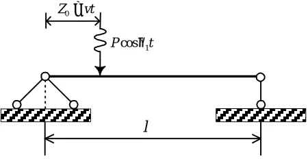
It is assumed that the moving load along the prismatic beam shown in Figure 1 varies in a harmonic manner. The potential and kinetic energy of this system can be written as follows [3]:
dz z w J G E L z w EJ ∫ ∂ ∂ − ∂ ∂ = ∏ 1 0 4 2 2 1 3 4 2 54 1 2 2 2 2 1 o (5) ∫∫ =∫∫ = ∫ ∂ ∂ = dxdy y J dxdy y J dz t w F E 4 1 , 2 , 2 1 0 2 1 o ρ (6)
where E, G, L2, ρ and F denote modulus of
elasticity, shear modulus, nonlinearity coefficient, density and cross sectional area respectively. The work of external load can also be expressed as:
( )
dzk l wzt
z k l z k l t P
A= ∫ ∑ =1 ⋅ ⋅
0 1sin sin ,
1 cos .
2 θ π o π
(7)
In which where θ1 is circular frequency of external load. The principle of Hamilton for this beam is as follows [4]:
[
]
∫∫ ∂ ∂ − ∂ ∂ = ∫∏− − = 4 2 2 1 3 4 2 54 1 2 2 2 2 1 z w J G E L z w J E dt E A H o( )
dzdt t w F t z w l z k k l z k l t P ∂ ∂ − ⋅ ⋅ ∑ = ⋅ − 2 2 1 , sin 1sin 1 cos 2 ρ π π θ o (8)Substituting ξ = πz/l and τ = ωt, the above equation may be rewritten as:
∫∫ ∂ ∂ − ∂ ∂ = 4 2 2 8 8 1 3 4 2 54 1 2 2 2 4 4 2 1 ξ π ξ π πω w l J G E L w l J E l H o vt Z0=
t Pcosθ1
l
( )
τ ξ τ ω ρ τ ξ ξ ξ ω θ d d w F w k k k t l P ∂ ∂ − ⋅ ⋅ ∑ = ⋅ − 2 2 2 1 , sin 1sin 1 cos 2 o (9)Assuming p(ξ) and q(τ) as the coordinate and generalized functions, deformation of the beam can be expressed in the following form [5]:
( ) ( ) ( )
ξ τ p ξ qτw , = ⋅ (10)
Substituting Equation 10 in Equation 9 and further simplifications the Hamilton principle is rearranged as: ∫ + − − = ∫ = τ πω τ ω
πω Ld
l d q d q c bq aq l H 1 2 2 4
2 (11)
where the coefficients a, b, c and d1 are:
( )
[
]
( )
[
]
( )
[
]
l vt k t l P d d p F c d p l J G E L b d p EJ a π θ π ξ ξ ρ ξ ξ π ξ ξ π sin . 1 cos 1 2 2 1 4 " 8 8 1 3 4 2 54 1 2 " 4 1 4 2 1 = ∫ = ∫ − = ∫ = o (12)Using the variation analysis by means of Euler method one can write [ 6].
τ ω θ ω θ π ω τ τ sin 1 cos 2 2 2 1 " 2 0 ⋅ = + + = ∂ ∂ − ∂ ∂ ∂ ∂ ∂ cl P q a b q c a q q L q L (13)
By substituting θ = kπv/l and q d X
2 0
ω
= in Equation 13 it can be written as:
ητ τ η ω ω sin . 1 cos 2 4 2 2 1 2 1
" =
+ ⋅ + X a bd X c a X (14) where ω θ η ω θ η
π = =
= , , 2 1 1 d p d Considering 4 2 2 ω d a b
e= ⋅ and
c a
= =ω0
ω the
Equation 14 is simplified as follows:
ητ τ η1 .sin cos
2 1
" =
+
+X eX
X (15)
The above equation is a DUFFING type ordinary differential equation and the general solution can be assumed in the following form [7]:
( )
τ =∑Xncosη1τ.sinητX (16)
Substituting Equation 16 in Equations 15, and comparing the results with similar cases of coefficients of cosη1τ.sinητ, many algebraic equations result, To our knowledge there is no exact solution for these equations and it would be appropriate to employ an approximate method, and
1
≥
n when Xn≤X1, n > 1 so it is applied the first constraint of Equation 16 that is:
( )
τ η τ.sinητ1 cos 1 X
X = (17)
By substitution of Equation 18 in Equation 15 and comparing the same coefficients, it will be:
1 3 1 4 3 1 2 1 2
1 + =
−η −η X eX (18)
If 12
2
2 η η
µ = + , Equation 18 can be rewritten as follows: 1 3 1 4 3 1 2
1 + =
−µ X eX (19)
From where the vibration amplitude can be determined.
From Equation 19 it can be concluded that the resonance of the system depends on the velocity and the circular frequency of load. Knowing X1 and considering Equation 10, the deflection of beam can be derived as below[8]:
( )
( )
l vt t z p X d t zw θ π
ω2 1 .cos 1.sin
Where 2 ω
d
is defined as follows:
( )
[
]
∫ = ξ ξ πω EJ p d
Pl d 2 " 3 3 2 o (21)
Stress at any cross section of the beam can be found as: − = 3 3 3 2 27 2 z G E L z E
z ε ε
σ (22)
Where 2
2 z w y z ∂ ∂ =
ε and L2 is physical nonlinearity coefficient.
The bending moment of the beam at any cross section can also be found as follows [9]:
∂ ∂ ⋅ − ∂ ∂ = ∫∫ ∂ ∂ − ∂ ∂ = ∫∫ ⋅ = 2 2 2 0 1 3 3 2 27 2 1 2 2 0 3 2 2 3 3 2 27 2 2 2 2 z w J J G E L z w J E dxdy z w y G E L z w y E ydxdy z M σ (23)
When the load is out of the beam which represents the free vibration of the beam, the equation of motion can be written as:
0 2 2 1 "
2 =
+ + q a b q c a q ω (24)
Finally, by solving Equation 24, the period of vibration can be calculated by the following equation:
( )
( )
( )
+ + + + = + = ... 6 sin 256 25 4 sin 64 9 2 sin 4 1 1 2 . / 2 1 . 4 θ θ θ π θ θ ω k k a bQ c a T (25) Therefore, the circular frequency of the system will be[10]:( )
) ( 1 . / 2 1 2 θ π ω k a bQ ca +
= (26)
where Q is the amplitude of vibration and k(θ) is a second order elliptic integral.
To better demonstrate this analysis, an example is presented in this part. It is necessary to mention that in the present solution the theory of Konform Inkas is used. It is assumed that the beam under study is made of copper.
From the Konform-Inkas solution and taking 4
, 9 1 1= q=
m .
The moment of inertia J° and parameter J1 are obtained as follows [112]:
6 1 0918 . 0 6 2 6 1 5509717 . 1 2 . 32 1 1 4 1 2458 . 0 4 3 4 1 3086417 . 3 2 . 24 1 A R A i i J A R A i i J π π π π = − = = − = o where
(
)
21 1 1 1 − − = q
m and q defines symmetrical axes at cross section.
y
x
cm b1=10
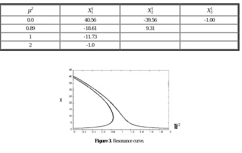
TABLE 1. Amplitudes of Vibration.
µ2 X11
1 2
X X13
0.0 40.56 -39.56 -1.00
0.89 -18.61 9.31
1 -11.73
2 -1.0
2
µ
x
Figure 3. Resonance curve.
TABLE 2. Deflection in the Point of Load.
0
Z
8
l
4 l
8 3l
2 l
8 5l
4 3l
8 7l
T(sec) 0.00227 0.0045 0.0081 0.0091 .011 .013 .016
W(cm) -0.065 -0.205 -0.3 -0.28 -0.18 -0.06 .001
TABLE 3. Bending Moment in the Middle Section of Beam.
8 71
4 31 8
51 2
l 8
31
4
l
8 l
Z0
-0.7 23.2
66.1 100.6
106.8 75.2
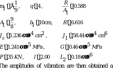
For the beam under study which is shown in Figure 2, the parameters used are as follows:
6 10 18 . 0 2 00 . 2 ,
35
5 10 46 . 0 ,
5 10 241 . 1
6 4 10 44 . 58 1 ,
2 4 10 236 . 1
616 . 6 ,
10 1 ,
8 9 1
588 . 0 1 ,
4 ,
9 1 1
× = =
=
× = ×
=
× = ×
=
= =
=
= =
− =
L l
KN P
MPa G
MPa E
cm J
cm J
R cm b
A
A R q
m
o
The amplitudes of vibration are then obtained as shown in Table 1.
Based on the data in Table 1, the resonance curve is as shown in Figure 3.
Consequently stress, deflection, and bending moments are obtained and presented in Tables 2-4.
Distribution of the stress caused by bending moment in the mid-beam’s cross section is shown in Figure 4.
3. CONCLUSION
The effect of material nonlinearity on the response
parameters of beam under concentrated harmonic load are investigated analytically. By using Hamilton principles and Euler's equations the nonlinear vibration equation of the system are obtained. The Fourier series is used to decompose the deflection as a multiplication of functions in time and space. The resulting equation in time is the well known Duffing's equation. Solving the Duffing equation by perturbation method the response parameters of the system is evaluated. In the case of linear material under concentrated moving load, theoretically with increasing the speed of the moving load resonance might happen. However, considering the material nonlinearity, resonance does not happen and the internal forces will have definite values. Taking into account the material nonlinearity, the internal forces for velocities blew critical velocity reduce as much as 10-15 percent in comparison with the linear case. Using these results, the dynamic amplification factors for the system are calculated. Increasing the material nonlinearity results in decreasing in the value of vibration amplitude.
4. REFERENCES
1. Kesiliev,V.A. Structural mechanic , Soviet Scientific and TABLE 4. Stress in the Middle Section of Beam.
Y(cm) 6.61 8.3 10
σ
(MPa) 54.189 65.715 75.710y
x
Figure 4. Section of beam.
technical literature, Moscow,550 p,1972.
2. Kauderer, H., “Nichtlinnear Mechanic”, Springer Verlag, Berlin, (1958), PII: S0020 -7683 (99) 00029-3.
3. Meirovitch, L., “Principles and Techniques of Vibrations”, (1997), ISBN 9780023801419.
4. Nayfeh, A.H. and Mook, D.T., “Nonlinear oscillations”, Willy Classics Library Edition Published, (1997), 56-58. 5. Clough, R.W. and Pennzien, J., “Dynamics of Structures”,
McGraw-Hill, New York, U.S.A., (1993).
6. Mardani, E., “The Nonlinear Behavior of Materials under Moving Loads”, In the Tenth Est. Asia-Pacific Conference on structural Engineering and Construction (EASEC–10), Bangkok, Thailand, (3-5 August, 2006). 7. Bicin, B., “Vibration of Beams with Multiple open cracks
subjected to Axial Forces”, Journal of Sound and Vibration, Vol. 222, No. 3, (1999), 409-423.
8. Ghorashi, M. and Nitzche, F., “Nonlinear Dynamic
Response of an Accerating Composite Rotor Blade using perturbations”, Journal of Mechanics of Materials and Structures, Vol.4, (2009), 693-718. 9. Mardani, E. and Garibov, R., “Physical Nonlinear of a
Prismatic Beam under Moving Continuous Distributed Load”, Scientific works in Structural Mechanic, Baku, ELM, No. 7, (1997), 75-80.
10. Sadhakar, R., “Advances in nonlinear Vibration analysis of Structures”, Sadhana Academy Proceedings in Engineering Sciences, DOI: 10.1007/BF02703386, Vol. 26, No. 3, (June 2001), 243-249.