A Novel Encoding Scheme for Cross-Talk Effect
Minimization Using Error Detecting and
Correcting Codes
Souvik Singha
National Institute of Technology, Durgapur, India Email: [email protected]
G. K. Mahanti
National Institute of Technology, Department of Electronics & Communication Engineering, Durgapur, India Email: [email protected]
Abstract—In this paper a new bus encoding method presented for reducing crosstalk effects, which can avoid crosstalk and provide error- correcting as well. This method find a subset from cross talk avoidance code (CAC) to provide error correction which allows to reduce the crosstalk- induced delay with buses implementing an error detecting/correcting code. Here we propose Fibonacci representation of single error correcting codes using Hamming code to avoid crosstalk induced delay. Extra wires for checking bus are never required in the proposed method and it can also improve bus performance and reduce power dissipation. We give algorithms for obtaining optimal encodings and present a particular class of error free codes. Conversely other bus encoding techniques have been used to prevent crosstalk but don’t correct error.
Index Terms
—bus-delay, crosstalk, encoding, error-
correction, interconnect, SECI. INTRODUCTION
Coupling noise between signal lines are a potential cause of failure in high speed electronic systems [1], [2]. Aggressive scaling in lateral dimensions with relatively unchanged vertical dimensions in sub- micron complementary metal - oxide - semiconductor (CMOS) very large scale integration (VLSI) causes the coupling capacitance between adjacent lines to become a significant fraction of the capacitance to the substrate [3]. The crosstalk has become a major concern because of continuing decrease in transistor sizes and the corresponding increase in chip density and operating frequencies. It has become a deciding design factor on total power consumption and delay of on chip data buses. The characteristics of data buses and long- interconnect such as wire spacing [4], [5]. Hence the crosstalk depends on the magnitude of the coupling capacitance which occurs between data bus paths and between interconnects. As a results these buses and interconnects becoming more sensitive crosstalk causes effects [6]. [7]. Crosstalk and
Manuscript received November 12, 2013; revised March 7, 2014.
delay faults can be reduced by reducing the coupling transitions [8]. The coupling capacitance not only depends on space between metal paths but also on the data dependent transitions and on the relative switching activity between adjacent bus wires [9], [10]. On-chip data buses play an important role in reliable communication and high- performance chips. Cross talk results due to charging and discharging of a coupling transition of a signal on data buses in the one of the attractive way of reducing the crosstalk. Cross talk avoidance codes can be used to reduce the effective coupling capacitance of a wire segment [11], [12], [13]. The crosstalk avoidance codes reduces the coupling capacitances and hence results in minimization of crosstalk, crosstalk induced delay, power dissipation and improvement in signal integrity, when crosstalk avoidance codec are combined with error detecting and correcting codes then signal integrity is improved [14], [15], [16], [17]. Several types of methods can identify crosstalk- induced errors ( CIEs) effecting the bus lines, this are then mask able by proper recovery techniques to achieve fault tolerance [18]. Alternatively, it is possible to implement error- correcting codes (ECCs). Among all existing ECCs, Hamming codes are a widely employed class of single error- correcting (SEC) codes [19], [20]. They are optimal in the number of parities m (m being the lowest integer such that 2m ≥k+ m + 1) for k information bit. Here we introduced Fibonacci representation of single error correcting codes (FRSECC) using Hamming codes which provides significant power savings compared to other ECCs and reduce the crosstalk in bus wire.
II.GENERAL SCHEME FOR BUS ENCODING MODEL
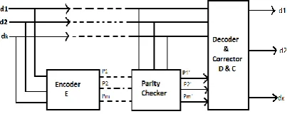
A general scheme using error correcting codes for bus encoding techniques is shown in Fig. 1. The k information bit (d1, d2, …, dk) go to the inputs of encoder (E), which produces m parity check output bits ( p1 … Pm ). These n = k + m bits form a codeword and are transmitted on the bus, belonging to a code space with a minimum Hamming distance dmin required to achieved the desired degree of error correction [13 ], [15], [21]. At the other end of the bus, there is a circuit (parity check), which recomputed the parity bits from the received data and compared them with those transmitted on the bus, thus generating vector
} ... ,
{p'1 p'2 p'm , with m = n – k bits. At the receiving position of the which detects and corrects the possible errors which might have occurred on the bus.
The encoding and decoding operations introduce a delay which depends on the code structure and on its error correction capability. For instance, for system implementing a Hamming code, the encoder consists of a series of XOR gates, which depends on the code structure and on its error correction capability, which influence the encoding/ decoding circuit complexity.
Figure 2. Capacitance of a 3 wire bus model
TABLE I. TOTAL EFFECTIVE CAPACITANCE IN CROSS TALK CLASSES
0C
CTOT (Effect) = CBOT
The victim and one aggressor switch in the same direction.
1C
CTOT (Effect) = CBOT + CC
The victim and one aggressor switch in the same direction and other aggressor is quite.
2C
CTOT (Effect) = CBOT + 2CC
The victim and one aggressor in same direction and other aggressor switch oppositely.
3C
CTOT (Effect) = CBOT + 3CC
The victim and one aggressor switch oppositely and other aggressor is quite.
4C CThe victim and both aggressor switch oppositely. TOT (Effect) = CBOT + 4CC
III. CONSIDER WIRE MODEL
As schematically shown in Fig. 2, [15] represent the capacitance of a three wire bus model where CB [F/m] is the contribution of the wire to the bottom parallel plate. CE [F/m] is the wire edge to the bottom and CC [F/m] is the wire to wire lateral component. In an inner wire (a wire in the middle of the bus) total bottom capacitance is CBOT (s) = CB + 2 CE (s). For an outer wire which has a shield, so
, ) ( ) ( )
( '
' s
C s C C s
CBOT B E E where C'E(s)CE(s)CC(s) , ),
( ) ( ) (
' s
C s C s
CBOT BOT C s is the spacing between adjacent wires. Capacitance CE increase with s as exp [(-1)
'
). ( ) ( 2 )
(s C s C s
CTOT C BOT For a (9, 4) Hamming Code,
we can distinguish nine different cases resulting in five different delays in a first order approximation. The total effective capacitance by the driver of the central (Victim) wire for different transaction of the two adjacent (Aggressor) wires is introduced in three wire bus model. Now we are reporting a five delay condition in detailed. The cross-talk classes and delay for various transitions are given in Table I.
IV. PROPOSED OPTIMAL CROSSTALK REDUCTION TECHNIQUE
Hamming codes are very efficient as single error correcting codes and in this section, we present two such mechanisms for error correction. In the first mechanism we propose a (9, 4) Hamming code scheme which reduces the bus delay. In the second mechanism we propose an optimal (7, 4) mechanism which gives better results than the formers.
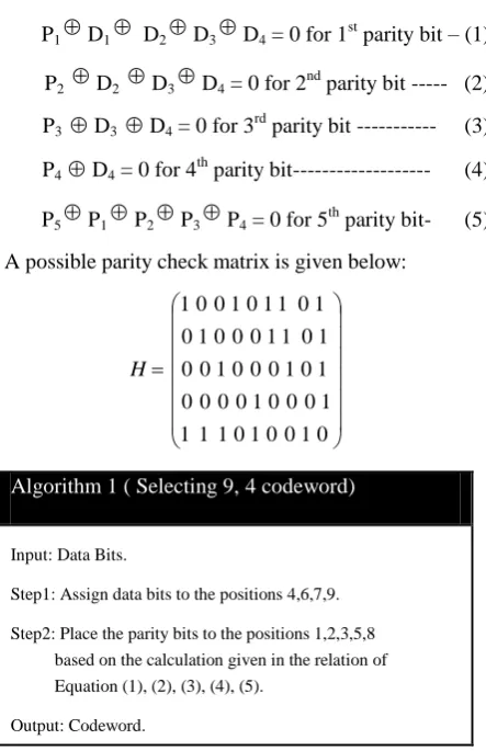
A. (9, 4) Hamming Code Using Fibonacci Series In this section we consider the Fibonacci series to implement error detection and correction. First we assign data bits to the positions 4, 6, 7 and 9. For the parity bits positions 1, 2, 3, 5 and 8 are allocated. Without loss of generality we discard the first element of the Fibonacci series. To compute the codeword the following selections are to be satisfied, where each parity bit represents the combination of data bits.
P1D1 D2D3D4 = 0 for 1st parity bit – (1)
P2 D2 D3D4 = 0 for 2nd parity bit --- (2) P3 D3 D4 = 0 for 3rd parity bit --- (3) P4 D4 = 0 for 4
th
parity bit--- (4)
P5P1P2P3P4 = 0 for 5th parity bit- (5) A possible parity check matrix is given below:
0 1 0 0 1 0 1 1 1
1 0 0 0 1 0 0 0 0
1 0 1 0 0 0 1 0 0
1 0 1 1 0 0 0 1 0
1 0 1 1 0 1 0 0 1
H
Algorithm 1 ( Selecting 9, 4 codeword)
Input: Data Bits.
Step1: Assign data bits to the positions 4,6,7,9.
Step2: Place the parity bits to the positions 1,2,3,5,8 based on the calculation given in the relation of Equation (1), (2), (3), (4), (5).
As the code word is generated the parity check matrix can be used for error detection and correction. This can be expressed with the help of an example.
Let us consider a 4-bit data, say 1010. From the positions of the data bits and parity bits, with the given relations of equations (1), (2), (3), (4), (5), the code word is created, which is shown below:
0 1 1 1 0 0 1 0 0
Now we multiplying the parity check matrix by the code word produces a ‘syndrome’ is given below:
0 0 0 0 0 0 0 1 0 0 1 1 1 0 0 1 0 0 1 0 1 1 1 1 0 0 0 1 0 0 0 0 1 0 1 0 0 0 1 0 0 1 0 1 1 0 0 0 1 0 1 0 1 1 0 1 0 0 1
If the syndrome is all zeros, the encoded data is error free as with this case. But if the syndrome has a non zero value, the column in the parity check matrix that matches the syndrome is the position where error has occurred. Flipping the encoded bit in this position will result in a valid code word.
B. Encoding Technique Based on (7, 4) Hamming Code
In this scheme, positions 2, 4, 6, 7 are assigned to data bits and positions 1, 3, 5 are allocated to parity bits. The code word is computed based on the following relations.
P1 = D2D3D4 --- (6) P2 = D1D3 D4 --- (7) P3 = D1D2D4 --- (8) Now the parity check matrix is given by
1 0 1 1 0 1 0 1 1 0 0 1 1 0 0 1 0 1 0 0 1 H
Algorithm 2 ( Selecting 7, 4 codeword)
Input: Data Bits.
Step1: Allocate data bits to 2,4.6,7 positions
Step2: Put the parity bits to 1,3,5 positions computation given in Equation (6),(7),(8).
Output: Codeword.
To illustrate this method we consider the same example of (9, 4) algorithm. The data bits and parity bits are
positioned accordingly using Equations (6), (7), (8), generating the code word is given below:
1 1 0 0 1 1 0
Now, the parity check matrix and the code word are multiplied in a similar way to produce the syndrome.
0 0 0 0 1 1 0 0 1 1 1 0 1 1 0 1 0 1 1 0 0 1 1 0 0 1 0 1 0 0 1
Similar to the previous example all zeros in the syndrome indicate error free data. Any non zero value in the syndrome gives the positions of the error in the corresponding parity check matrix.
V. ERROR DETECTION AND CORRECTION CIRCUIT MODEL
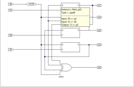
Error detection and correction circuits of the proposed encoding scheme are given in Fig. 3, and Fig. 4, respectively. These bus configuration techniques have minimal hardware overhead compared to the other encoding schemes. Here in (9, 4) systematic SEC code need to add 5 check bits, leading to a code word length of 9 bits. But in a single error correcting (7, 4) Hamming code is implemented, need only 3 check bits, leading to a codeword length 7 bits. Analyzing the code space, composed by 16 code words therefore, combining the (9, 4) code with non- uniform inter- wire spacing, we can achieve an energy saving of 12% with respect to the (7,4) Hamming code. Furthermore, it is worth noticing that the proposed (7, 4) code requires less gates than the existing Hamming code, thus providing further power savings. It can be noticed that if we consider a (7, 4) Hamming code with the bus wires at minimum spacing.
Figure 4. (7, 4) Hamming circuit for proposed algorithm with single error correction and detection
VI. SIMULATION RESULTS
Figure 5. Fibonacci based (9, 4) SEC Hamming Code Circuit output
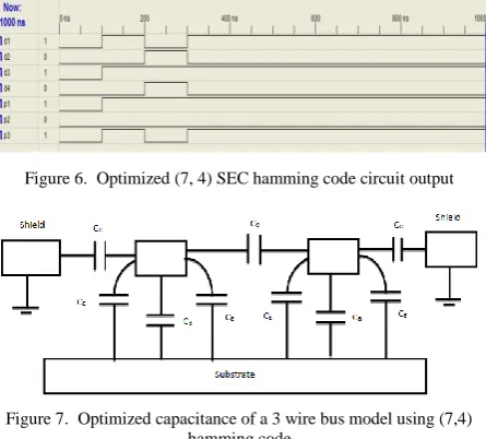
Figure 6. Optimized (7, 4) SEC hamming code circuit output
Figure 7. Optimized capacitance of a 3 wire bus model using (7,4) hamming code
In the proposed bus configuration, the crosstalk effect on a delayed wire is smaller than that of a conventional case, resulting in a bus delay reduction. The reason for the maximum bus delay reduction is that the time shift between adjacent wires, introduced by the encoding circuit, limits the Miller effect and consequently reduces the value of the effective capacitance of a delayed wire. Here we introduced SEC Fibonacci representation (9, 4) and an optimal (7, 4) Hamming code which reduced the crosstalk induced bus delay provided by the considered coding techniques and our experimental results shown in Fig. 5, and Fig. 6. For instance, a bus implementing (7, 4)
in Fig. 7, examine the total effective capacitance driven by two adjacent (aggressor) lines where (i) One aggressor is working and other is quite. i.e. CTOT = CBOT . (ii) Both aggressor in same direction. i.e. CTOT = CB + CE + CE + CC = CBOT + CC. (iii). Both aggressor switches oppositely. i.e. CTOT = CBOT + 2CC.
So the encoding scheme, which eliminates crosstalk classes 4, 5 and 6 results in less delay compared to un- encoded data and other schemes.
VII. CONCLUSIONS
In this paper, a novel bus encoding scheme for crosstalk effect and delay minimization along with error detection and correction for on- chip interconnects is proposed. We have shown that the redundancy introduced by error correcting codes can be exploited in order to avoid the worst case crosstalk- induced delay. In particular, we analyzed the cases of (9, 4) Hamming codes and (7, 4) Hamming codes, that we recently introduced to minimize bus delay consumption. Here a new error correcting codes, featuring uses Fibonacci series that represent data and parity bits which allow further crosstalk- induced bus delay and power- delay reduction with respect to existing single error correction hamming codes. Finally, we have shown that higher improvements can be obtained by an optimized (7, 4) SEC Hamming codes in the bus wires.
REFERENCES
[1] I. Catt, “Crosstalk (noise) in digital systems,” IEEE Trans. Electron. Comput., vol. 16. no. 6, pp. 743- 763, 1967.
[2] P. Larsson and C. Svensson, “Noise in digital dynamic CMOS Circuits,” IEEE J. Solid - State Circuits, vol. 29, pp. 655-662, June 1994.
[3] I. Gal, “On-chip crosstalk - the new signal integrity challenge,” in. Proc. Custom Integrated Circuits Conf., 1995, pp. 12.1.1-12.1.4. [4] P. Petrov and A. Orailoglu, “Low-power instruction bus encoding
for embedded processors,” IEEE Trans. VLSI Systems, vol. 12, no. 8, pp. 812-826, Aug. 2004.
[5] R. Sing, G. Choi, and R. N. Mahapatra, “Data handling limits of on-chip interconnects,” IEEE Transaction on Very large Scale Integration (VLSI) Systems, vol. 16, no. 6, June 2008.
[6] K. S.-M. Li, C.-L. Lee, C. Su, and J. E Chen, “A unified detection scheme for cross talk effects in interconnection bus,” IEEE Transaction on Very Large Scale Integration (VLSI) Systems, vol. 17, no. 2, Feb. 2009.
[7] Z. Khan, T. Arslam, and A. T. Erdogan, “Low power system on chip bus encoding scheme with crosstalk noise reduction capability,” IEE Proceeding, Computers and Digital Techniques, vol. 153, pp. 101-108, Mar. 2006.
[8] D. Rossi, A. K. Nieuwland, et al., “Power consumption of fault tolerance buses,” IEEE Transaction on Very Large Scale Integration (Vlsi) Systems, vol. 16, no. 5, May 2008.
[9] B. Victor, et al., “Bus encoding to prevent crosstalk delay,” in Proc. ICCAD, 2001, pp. 57- 63.
[10] C. Duan, A. Tirumala, and S. P. Khatri, “Analysis and avoidance of crosstalk in on-chip buses,” Hot Interconnects, pp. 133-138, 2001.
[11] Madhu, et al., “Delay and energy-efficient data transmission for on- chip buses,” in Proc. ISVLSI, 2006, pp. 355-360.
[12] D. Bertozzi, L. Benini, and B. Ricco, “Energy-efficient and reliable low-swing signaling for on-chip buses based on redundant coding,” in Proc. IEEE Intl. Symp. on Circuits and Systems, 2002, pp. 93-96.
Scale Integration (VLSI) Systems, vol. 12, no. 10, pp. 1076-1080, 2004.
[14] M. Favalli and C. Metra, “Bus crosstalk fault-detection capabilities of error-detecting codes for on- line testing,” IEEE Trans. on VLSI Systems, pp. 392-396, Sep. 1999.
[15] D. Rossi, S. Cavallotti, and C. Metra, “Error correcting codes for crosstalk effect minimization,” in Proc. 18th IEEE International Symposium on Defect and Fault Tolerance in VLSI Systems, 2003. [16] P. M. Chirlian, Analysis and Design of Integrated Electronic
Circuits, New York: Harper and Row, 1987.
[17] C. Metra, M. Favalli, and B. Ricco, “Self -checking detection and diagnosis scheme for transient, delay and crosstalk faults affecting bus lines,” IEEE Trans. Comput., pp. 560-574, June 2000. [18] D. Pamunuwa and H. Tenhunen, “Repeater insertion to minimise
delay in coupled interconnects,” in Proc. Fourteenth International Conference on VLSI Design, 2001, pp. 513-517.
[19] D. rossi, V. E. S van Dijk, R. P. Kleihorst, A. H. Nieuwland, and C. Metra, “Coding scheme for low power consumption fault tolerant bus,” in Proc. 8th Int. On-Line Testing Work, 2002, pp. 8-12.
[20] L. D. Silvio, D. Rossi, and C. Metra, “Crosstalk effect minimization for encoded bus,” in Proc. 9th Int. On-Line Testing Symp., 2003, pp. 214-218.
[21] B. Victor and K. Keutzer, “Bus encoding to prevent crosstalk delay,” in Proc. IEEE/ACM Int. Conf. on Computer Aided Design, 2001, pp. 57-63.
Mr. Souvik Singha is working as an Assistant Professor in the department of Computer Science & Informatics, Bengal Institute of Technology & Management, Santiniketan. He received his Diploma in Engineering (CST) und er West B en ga l B oa rd of Technica l Education in the year of 2002 and he received BE (CSE) under University of Burdwan in the year of 2005. He received his M.Tech in CSE under National Institute of Technology of Durgapur in the year of 2008. He is a PhD scholar of National Institute of Technology, Durgapur.