ISSN(Online): 2319-8753 ISSN (Print): 2347-6710
I
nternational
J
ournal of
I
nnovative
R
esearch in
S
cience,
E
ngineering and
T
echnology
(A High Impact Factor, Monthly, Peer Reviewed Journal) Visit: www.ijirset.com
Vol. 6, Issue 12, December 2017
Review on Estimation of Defocus Map using
LBP based Segmentation
Rammilan Chadhar1, Prof. Shalini Sahay2
M. Tech. Scholar, Department of Electronics and Communication, SIRT, Bhopal, India1 Associate Professor, Department of Electronics and Communication, SIRT, Bhopal, India 2
ABSTRACT: Defocus obscure is to a great degree basic in pictures caught utilizing optical imaging frameworks. It might be unwanted, yet may likewise be a deliberate masterful impact, in this way it can either upgrade or hinder our visual impression of the picture scene. For assignments, for example, picture rebuilding and protest acknowledgment, one might need to fragment an incompletely obscured picture into obscured and non-obscured locales. In this paper, the investigation of sharpness metric in light of nearby twofold examples and a vigorous division calculation to isolate all through concentration picture districts. The sharpness metric adventures the perception that most neighborhood picture fixes in foggy areas have altogether less of certain nearby parallel examples contrasted and those in sharp districts. Utilizing this metric together with picture tangling and multiscale derivation, we got amazing sharpness maps. Tests on many incompletely obscured pictures were utilized to assess our obscure division calculation and six comparator techniques. The outcomes demonstrate that our calculation accomplishes near division comes about with the cutting edge and have huge speed advantage over the others in additionally work.
KEYWORDS: Defocusmap,Defocus Blur, Segmentation, LBP Technique
I. INTRODUCTION
FOCUS blur in an image is the result of an out-of-focusoptical imaging system. In the image formation process, light radiating from points on the focus plane are mapped to a point in the sensor, but light from a point outside the focus plane lights up a non-point district on the sensor known as a hover of perplexity. Defocus obscure happens when this circle turns out to be sufficiently expansive to be seen by human eyes. In advanced photography, defocuses obscure is utilized to obscure foundation and “fly out" the primary subject utilizing vast gap focal points.
ISSN(Online): 2319-8753 ISSN (Print): 2347-6710
I
nternational
J
ournal of
I
nnovative
R
esearch in
S
cience,
E
ngineering and
T
echnology
(A High Impact Factor, Monthly, Peer Reviewed Journal) Visit: www.ijirset.com
Vol. 6, Issue 12, December 2017
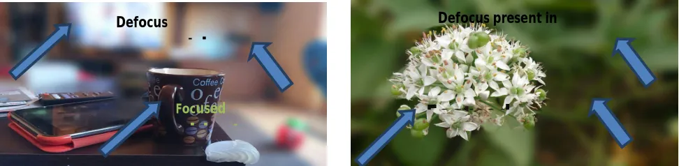
sharpness in front of and behind the subject on which the lens is focused. Thelower the f/stop the larger the opening in the lens (that is the maximum aperture) correspondsless depth of field and henceblurred background. In Fig (1) an example is shown in which imagedescribes defocus present in background and focused object.
Figure 1:Example showing defocus blur present in background
The 2D map for an image of the scale parameter is entitle asdefocus blur map, which indicate the point of local blur at each pixel in image. Edge detection is performed in Defocusestimation; edges in images are the areas with strong intensity contrasts. Gradient methods detect detects the edges by looking for maximum and minimum in the first and second derivative of image (image gradient is a directional change in intensity). In this paper our proposed method also estimating defocus by first taking image derivative and further blurring kernel is chosen which help in this method to model blur map.Optical imaging system is shallow depth of field due to which images are captured with sharp foreground (object present in image is focused) but blurred background (surroundings).
II. DEFOCUS BLURRING CONCEPT
As far as possible there are many methods for magnifying the defocus blur which is typically present in photographs. In this paper we introduced an effective method for defocus magnification. The magnified defocus blur present in background of images. By magnifying defocus we can conclude that output image looks more shafrp as compare to original image which suffers from defocus blurand our method gives good result as compared to other existing methods.
Firstly we will define the radius of blurring kernel by which blurring can be performed in the whole image. So, we define radius of blurring kernel given as:
[ ]=Max[ ](1)
Where, dA is the 1st derivative of image function.And is mean of kernel which is given as; =∗ ∑, , and i, j =0, 1…….I, J (2)
I=J= int[r]
And I & J are the window size dimensions. The blurring kernel radius value will decide the amount of blurring. Now, to get the result from the above concept we are performing convolution. So,
Defocus
present in
Focused
object
Focused
ISSN(Online): 2319-8753 ISSN (Print): 2347-6710
I
nternational
J
ournal of
I
nnovative
R
esearch in
S
cience,
E
ngineering and
T
echnology
(A High Impact Factor, Monthly, Peer Reviewed Journal) Visit: www.ijirset.com
Vol. 6, Issue 12, December 2017
From the above result we get the image in which blurring is performed according to radius of blurring kernel and by which defocus present in image is blurred more and our main focused object looks much more sharp.
Then thresholding is performed which determines the pixels which should be discarded and also those pixels which should be retained in our image. The Otsu's method search for the threshold that minimizes the intra-class variance that signifies that the variance within the class which is defined as a weighted sum of variances of the two classes:
( ) = ( ) ( ) + ( ) ( )(4)
Where weight are the probabilities of the two classes divided by a threshold t and variances of these classes. At last the localization is done which gives the exact blur map. After the localization we get the blur map for gray image as well as color image and map for defocus magnification.
Figure 2: Defocus Blurring Concept
Important image features can be extracted from the image edges. Extracted features are employed for higher level computer vision algorithms (recognition). Before obtaining the blur map we first employ Gaussian filter to reduce the noise effect this operation in general termed as smoothing. The filtering is useful for noise reduction (side effect blurring).After the smoothing operation the noise is suppressed as much as possible and hence demarcation is done on the outcome of Gaussian filter for enhancing the quality of map. After Gaussian smoothing thresholding is performed this decides the pixels which should be discarded and also those pixels which should be retained from the image. As a last step localization is performed this gives the exact blur map (exact edge location).
For removing high frequency noise a Gaussian filter with small kernel is applied to the original image so it will remove high-frequency noise and suppress the blur caused by blur texture.
The Gaussian distribution in 1-D has the form:
( ) = 1
√2 (5)
Where is the standard deviation of the distribution which controls the smoothing. We have assumed that the distribution has mean of zero (i.e. it is centered on the line x=0).
ISSN(Online): 2319-8753 ISSN (Print): 2347-6710
I
nternational
J
ournal of
I
nnovative
R
esearch in
S
cience,
E
ngineering and
T
echnology
(A High Impact Factor, Monthly, Peer Reviewed Journal) Visit: www.ijirset.com
Vol. 6, Issue 12, December 2017
( , ) = 1
2 − (6)
Once a suitable kernel has been designed, then the Gaussian smoothing can be accomplishedby using standard convolutionmethods. The convolution is accomplished fairly rapidly since the equation for the 2-D isotropic Gaussian shown above is detachable into x and y components. Thus the 2-D convolution can be obtained by convolving with a 1-D Gaussian function in the x direction, and then convolving again with one 1-D Gaussian in the y direction. After the Gaussian smoothing enhancement is done for enhancing the result obtained from Gaussian filtering that means sharpening is done by means of demarcation. Demarcation measures the rate of change of a function and demarcation is done on the outcome of Gaussian filter for enhancement the quality of map.
The formula for the 1st derivative of a function is as follows:
= ( − ) ( − ) (3)
Where represents the pixel value.
At the end of this we will get the image in which it is shown that the high contrast region are mainly focused and out of focus region is having low contrast so it is demarcated .
III. RELATED WORK
Xin Yi et al. [1],proposed that camera shake during exposure may cause objectionable blur in images and damage photographs. Defocus blur is extremely common in imagescaptured using optical imaging systems. It may be undesirable, but may also be an intentional artistic effect, thus it can either enhance or inhibit our visual perception of the image scene. For tasks, such as image restoration and object recognition, one might want to segment a partially blurred image into blurred and non-blurred regions. In this paper, we propose sharpness metric based on local binary patterns and a robust segmentation algorithm to separate in- and out-of-focus image regions. The proposed sharpness metric exploits the observation that most local image patches in blurry regions have significantly fewer of certain local binary patterns compared with those in sharp regions. Using this metric together with image matting and multiscale inference, we obtained high-quality sharpness maps. Tests on hundreds of partially blurred images were used to evaluate our blur segmentation algorithm and six comparator methods.
The results show that our algorithm achieves comparative segmentation results with the state of the art and have big speed advantage over the others.
J. Shi et al.[2],proposedan edge detection technique in which edge detection is performed according to the first- and second-order derivatives of the input photograph. They used the Gaussian basic filter which calculate the center line of edges and respective blur response, their method perform edge detection using local scale control and their result gives only sparse defocus map(in which high contrast edges are highlighted). There are two approaches for edge detection search based and zero crossing.
ISSN(Online): 2319-8753 ISSN (Print): 2347-6710
I
nternational
J
ournal of
I
nnovative
R
esearch in
S
cience,
E
ngineering and
T
echnology
(A High Impact Factor, Monthly, Peer Reviewed Journal) Visit: www.ijirset.com
Vol. 6, Issue 12, December 2017
K. He et al. [4],technique model the blur mapby applying local contrast prior whichmeasured the defocus at each pixel and then MRF propagation used to refine the defocus map. The input picture is re-blurred by using a known Gaussian blur kernel and the ratio stuck between the gradients of input and re-blurred images is calculated. In this paper we have proposedawell-organized blur estimation method based on radius of blurring kernel and our proposed method is robust to noise and intrusion from neighboring edges. Without any revision to cameras or using additional illumination we can say that our method is able to obtain the good defocus map of an image captured by conventional camera.
R. Fergus et al. [5], developedan method for restoring sharp image and produce blur map their method select best PSF.This technique requires specially designed aperture filter which heavily limits its domain of application. The recommended a method estimating the likelihood function of a given candidate (point spread function)PSF which is based on local frequency component analysis without deconvolution and this method is applied to detect motion blur but also applied for defocus blur identification. The introduced spectrum contrast approach for estimating defocus map from a single image. According to this approach blur affects the spectrumamplitude at the object edge only and edges contains the maximum information.This also takes contemplation in smoothness and color edge information to construct a coherent blur map that marks the amount of blur at each pixel. They have shown the comparison of various methods and different methods have been reviewed for estimation of defocus blur.
Table 1: Summary of Literature Review
Title Methodology Parameter Scope
LBP-Based Segmentation of
Defocus Blur
Sharpness metric based on local binary patterns and a robust
segmentation algorithm
Average runtime = 27.75 sec, Precision = 0.85,
recall = 0.82
Optical image system
Just noticeable defocus blur detection and estimation
Design defocus blur image using complex wavelet
transform system
F-measure = 0.92, recall = 0.84
High-resolution imaging
Learning to estimate and remove non-uniform image blur
Design defocus blur image using singular value
decomposition
Average runtime = 27.75 sec,
Digital Camera
A global sampling method for alpha
matting
Sparse dictionary based on a large external set of
defocus images
Sparsity Feature Value = 55, recall = 0.88
Digital photography
Design of Removing camera shake from a
Single image
Edge width as a reference for depth measurement based
defocus
Recall = 0.91, Precision = 0.91
Digital camera and optical system
The identified shadow elements are improved by intensity biased so as to maintain the intensity level of shadowed region equivalent to the non-shadow region. To do this process we have divided the whole shadow region into four parts and differently adjusted the intensity level to get high quality shadow removed image.
The simplest assumption that can be used to detect cast shadows is that regions under shadow become darker as they are blocked from the illumination source. Furthermore, since there is also ambient illumination, there is a limit on how much darker they can become. These assumptions can be used to predict the range of intensity reduction of a region under shadow, which is often used as a first stage to reject non-shadow regions. However, there are no methods which rely primarily on intensity information for discriminating between shadows and objects.
ISSN(Online): 2319-8753 ISSN (Print): 2347-6710
I
nternational
J
ournal of
I
nnovative
R
esearch in
S
cience,
E
ngineering and
T
echnology
(A High Impact Factor, Monthly, Peer Reviewed Journal) Visit: www.ijirset.com
Vol. 6, Issue 12, December 2017
but the chromaticity remains the same is normally referred to as colour constancy [5]. Pixels in a shadow region usually have large hue value, low blue color value, and small difference between green and blue color values [6].
The detection stage in which shadow regions are detected, specifically by determining the shadow boundaries and the reconstruction stage in which the shadow is actually removed and a shadow-free image is produced
IV. PROBLEM FORMULATION
The shadow removal problem can be broken down into two main constituent parts: shadow identification and shadow removal. Shadow identification is a well-defined concept, in which the presence of shadows upon different material image surfaces is detected and their exact position upon those surfaces is located. We primarily focus on shadow removal upon any one of these material surfaces. We assume that such an identification method has recognized a surface as having a shadow on it and passed it to our algorithm.
Our shadow removal approach is based on a simple shadow model where lighting consists of directed light and environment light. We try to identify how much direct light is occluded for each pixel in the image and relights the whole image using that information. First, we use a matting (extracting a foreground element from a background image by estimating an opacity for each pixel of the foreground element) technique to estimate a fractional shadow coefficient value. Then, we estimate the ratio of direct to environmental light, which together with the shadow coefficient, enables a shadow-free image to be recovered.
V. CONCLUSIONS
In this paper, review is very simple yet effective sharpness metric for defocus blur segmentation. This metric is based on the distribution of uniform LBP patterns in blur and non-blur image regions. The direct use of the local raw sharpness measure can achieve comparative results to the stat-of-the-art defocus segmentation method that based on sparse representation, which shows the potential of local based sharpness measures. By integrating the metric into a multiscale information propagation frame work, it can achieve comparative study with the state-of-the-art.
REFERENCES
[1] Xin Yi and Mark Eramian, “LBP-Based Segmentation of Defocus Blur”, IEEE Transactions on Image Processing, Vol. 25, No. 4, April 2016. [2] J. Shi, L. Xu, and J. Jia, “Just noticeable defocus blur detection and estimation,” in Proc. IEEE Conf. Comput. Vis. Pattern Recognit. (CVPR),
Jun. 2015, pp. 657–665.
[3] F. Couzinie-Devy, J. Sun, K. Alahari, and J. Ponce, “Learning to estimate and remove non-uniform image blur,” in Proc. IEEE Conf. Comput. Vis. Pattern Recognit. (CVPR), Jun. 2013, pp. 1075–1082.
[4] K. He, C. Rhemann, C. Rother, X. Tang, and J. Sun, “A global sampling method for alpha matting,” in Proc. IEEE Conf. Comput. Vis. Pattern Recognit. (CVPR), Jun. 2011, pp. 2049–2056.
[5] R. Fergus, B. Singh, A. Hertsmann, S. T. Roweis, W. T. Freeman,” Removing camera shake from a Single image” in Proc. SIGGRAPH, 2006, pp. 787–794
[6] J. Elder, S. Zucker, Local scale control for edge detection and blur estimation, IEEE Trans. Pattern Anal. Mach. Intell. 20 (7) (1998). [7] S. Bae and F. Durand, “Defocus magnification,” Comput. Graph. Forum 26, 571 (2007).
[8] V. P. Namboodiri and S. Chaudhuri, in Proceedings of the IEEE Conference on Computer Vision and Pattern Recognition (CVPR) (IEEE, 2008), pp. 1–6.
[9] S. Zhuo and T. Sim, Pattern Recogn. 44, 1852 (2011).
[10] Y.-W. Tai, M. S. Brown, Single image defocus map estimation using local contrast prior, in: Proc. ICIP, 2009.
[11] A. Levin, R. Fergus, F. Durand, and W. T. Freeman, “Image and depth from a conventional camera with a coded aperture,” in Proc. SIGGRAPH .2007, p. 70.
[12] A. Chakrabarti, T. Zickler, and W. T. Freeman, “Analyzing spatially varying blur,” in Proc. IEEE CVPR, Jun. 2010, pp. 2512–2519
[13]Chang Tang, Chunping Hou, and Zhanjie Song “Defocus map estimation from a single image via spectrum contrast’’, OpticalSociety of America, Vol. 38, No. 10 / May 15, 2013.
[14] Xiang Zhu, Scott Cohen, Stephen Schiller, Milan far, “Estimating Spatially Varying Defocus Blur From A Single Image” IEEE Transactions On Image Processing, Vol. 22, No. 12, pp.4879 -4891,Dec 2013.