Design and Implementation of Battery Charge
Controller Using Embedded Fuzzy Logic
System
K. A. Akpado1, C. P. A. Okwaraoka2, M. I. Aririguzo3
Senior Lecturer, Department of Electronics and Computer Engineering, UNIZIK, Awka, Anambra, Nigeria1
P.G. Student, Department of Electronics and Computer Engineering, UNIZIK, Awka, Anambra, Nigeria 2
Principal Lecturer, Department of Elect/Elect Engineering, Federal Polytechnic Nekede, Owerri, Imo, Nigeria3
ABSTRACT: In this work, Fuzzified battery charging system was designed and implemented using a PIC16F877A microcontroller. Three parameters of the battery (temperature, voltage and charging current) were monitored to fuzzylogically control the Pulse Width Modulated (PWM) output used to deliver the correct charging power. A Metal Oxide Semiconductor Field Effect Transistors (MOSFETs) was used as a switching device controlled with pulse width modulated (PWM) output of the microcontroller. The rule-base is populated with expert knowledge of best practices in lead acid battery charging. On test, the prototype fully charged a good 12V 100AH Valve Regulated Lead Acid (VRLA) battery in 7hrs, at an average energy transfer efficiency of 77%. 80% battery capacity was reached in less than 4 hours, without raising the battery temperature. The result marched what is obtainable with high quality lead acid battery Chargers, but at a low cost. Future implementation of fuzzy logic controller on 8bit microcontroller will benefit immensely from the rule base design methods used in this work.
KEYWORDS: Fuzzy, Fuzzification, embedded fuzzy, rule base, charger controller.
I.INTRODUCTION
Fuzzy logic technique has become the choice for development of products including consumer appliances, industrial process control, pattern recognition systems, medical instrumentation, information systems, signal processing and analysis. This is because of the success of fuzzy logic in the simplification of the seemingly complex control system design process.
Fuzzy logic is based on the experimental findings of experts in the particular field of application. Hence fuzzy controllers are able to make human like decisions when in the field of operation, using fuzzy rule base and inference engines.
ISSN(Online) : 2319-8753 ISSN (Print) : 2347-6710
I
nternational
J
ournal of
I
nnovative
R
esearch in
S
cience,
E
ngineering and
T
echnology
(An ISO 3297: 2007 Certified Organization)
Website: www.ijirset.com
Vol. 6, Issue 6, June 2017
portable devices we use. Incidentally, almost all the said chargers are imported. This implies not only high volume of electronics waste (for the disused portable devices), but also a lot of capital flight with high costs of foreign exchange (FOREX). In addition to this, importation of finished products cost more than importation of raw materials hence, local production is more economical. The embedded fuzzy logic controller for battery chargers designed in this work is one of such local solution to the problems of predominance of low quality battery chargers which can contribute to reduction in FOREX cost.
II. RELATEDWORK
Cong-Hui et-al used a computer controlled high end microprocessor (a DSP) to demonstrated a design of an intelligent solar charging system with fuzzy logic control method that showed how fuzzy logic method improved the efficiency of charging and suppressed abnormal battery temperature rise[2].
Swathika et al [3] used MATLAB to comparatively simulate fuzzy logic controlled lead acid battery charger and that of a PI based controller, showing that the PI based controller had more overshoots than the Fuzzy Logic controller, concluding that fuzzy logic controller has a better set point tracking at minimum time.
Alberto Sanchez successfully implemented a fuzzy logic controlled Nicad Cadmium battery charger using a Texas instrument microcontroller MSP430x337 [4], which is much more expensive than the low end PIC and Atmel microcontrollers as used in this work.
Brock J. LaMeres[5] in a design and implementation of fuzzy logic controlled voltage regulator for synchronous machines showed and adoptable approach to fuzzification, inference and defuzzification design stages, especially when designing for implementation on a low end microcontroller.
Ferenc Farkas and Sándor Halász in a comparative analysis of a DSP versus 16 bit microcontroller based fuzzy controller [6] showed that the difference in result is insignificant. They also opined that same result could be obtained from an 8bit microcontroller, which is part of what this work set out to achieve.
From the above, it is that there is a gap between theorizing and actual implementation of fuzzy logic controllers on low end 8bit microcontroller. Another fact is that Lead Acid batteries are the most common batteries used in our society today, and any effort made to affordably improve its lifespan and performance is therefore worthwhile.
This work tried to fill the gap of low end microcontroller implementation of fuzzy logic system, by designing and implementing a low cost fuzzy controlled lead acid battery charger on a PIC16F877A (a cheap 8bit microcontroller).
III. DEFINITIONOFTERMS
For convenience, lets define a few fuzzy terms to ease understanding of the information in this report.
2.1 Fuzzification: This is the process of converting numerical or crisp values to fuzzy values. Fuzzification operations map mathematical input values into fuzzy membership functions. [7]
2.2 Defuzzification: Defuzzification is the process that coverts fuzzy values into crisp or numerical values which can be applied for the purpose of control.[7]
2.3 Fuzzy Set: This is a set, in which element members are graded in their membership, usually between the values 0 and 1. 0 grade membership meaning total exclusion from the set, while grade 1 membership refers to total inclusion in the set.
Figure 1 Block Diagram of the Battery Charger based on Embedded Fuzzy logic controllers
2.4 Linguistic Variable: This can be defined as constant symbolic descriptions of what are in general time-varying quantities [7]. A linguistic variable or fuzzy variable represent crisp information in a form and precision appropriate for the problem being solved [8].
2.5 Rule Base: This specifies a set of rules that captures the expert’s knowledge about how to control the given plant [7]. In this case the plant is the VRLA battery under charge. Mamdani type Rule base is usually of the form “If x1 and x2 then y” statements, where “x1” and “x2” are called premises, and “y” is the consequence.
IV. METHODOLOGY
Since Fuzzy logic control method promotes reduced development time, Prototyping methodology was adopted in this work to aids speedy development. A functional model was made and tested to verify the concept of embedded fuzzy logic system based battery charger controller.
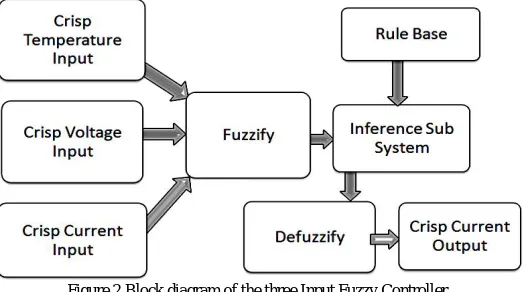
The Fuzzy Logic Controller module in this project is embedded in PIC16F877A microcontroller. The structure of the fuzzy controller is shown in a block diagram of figure 2 below;
ISSN(Online) : 2319-8753 ISSN (Print) : 2347-6710
I
nternational
J
ournal of
I
nnovative
R
esearch in
S
cience,
E
ngineering and
T
echnology
(An ISO 3297: 2007 Certified Organization)
Website: www.ijirset.com
Vol. 6, Issue 6, June 2017
Crisp Temperature; An LM35 temperature sensor is used to measure the battery temperature. The sensor is mounted on the battery terminal because SLA batteries are always enclosed in plastic material which is a poor conductor of heat. The rang 0-60oC is considered valid.
Crisp Voltage; Battery terminal voltage is sampled directly using a resistor voltage divider. The maximum internal reference voltage of the ADC inside the microcontroller is 5V. Therefore the voltage divider has to provide a range 0-5V for battery voltage of 0-10-5V variation.
Crisp Charging Current; A low value resistor is used in series with the positive battery terminal, so that charging current drops a proportional voltage to be converted by the ADC in the microcontroller.
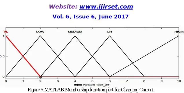
3.2 Fuzzification Process: Each linguistic variable is associated with an appropriate fuzzy set of linguistic values, represented with triangular membership functions (MFs). As illustrated in figure 2 above, the Crisp values of voltage, temperature and charging current of the battery are fuzzified in an operation that map the crisp input values into fuzzy membership functions (MFs) [7]. The resulting fuzzy values generated from the MFs shown in figures 3-5 below, are fed to the fuzzy inference sub-module.
Figure 3 below depicts the linguistic variable Temperature. It shows the linguistic values assigned to each MF under the universe of discuss – Temperature as COLD(CO), WARM(WA), HOT(HO) and VERY HOT(VH), within the valid range 0-60oC allowed for leads acid battery operations. Any value below or equal to 0oC is assigned to the MF COLD, while any value above or equal to 60oC is assigned to VERY HOT.
Figure 3 MATLAB Plot of Fuzzy Battery Temperature membership functions
Figure 4 below shows the MFs of Fuzzy voltage designed for 12V lead acid battery charging. The linguistic values VERY LOW(VELOW), LOW, NORMAL, LITTLE HIGH(LIHI) and HIGH are shown within the universe of discuss of voltage range for 12V lead acid battery. Any voltage value from 10V downward is regarded as VERY LOW, while voltage values from 15V upward is assigned to HIGH.
Figure 4 Plot of Fuzzy Battery Voltage membership functions
Figure 5 MATLAB Membership function plot for Charging Current
3.3 Degree of Membershipp: To compute degree of membership for any given crisp input using triangular MFs, the Side Side Side (SSS) postulate for similar triangles is applied. The expressions deduced for computing degree of membership for each linguistic variable is as follows;
µ ( ) =
⎩ ⎨
⎧ −
− <
… … … ( )
μ ( ) =
⎩ ⎨
⎧ −
− >
… … … ( )
where each MF is defined by 3 values [ , ](representing the position of the 3 vertices of the triangular MF in the universe of discuss).
For example, given a crisp battery voltage 13.5V, which belong to the two MFs NORMAL and HIGH to different degrees. Let us call the degree of memberships µVbatt(13.5V)NORMAL and µVbatt(13.5V)HIGH
From figure 4 above, the range of crisp values under the MF NORMAL is [11.75V to 13.75V], with 12.75V having the apex value 1 or highest degree of membership. While HIGH MF has crisp values range from [13V to 15.5V], with 14.4V having degree 1 membership.
Therefore, the degree of membership for Crisp value of 13.5V, is computed for only the two MFs NORMAL[11.75V, 12.75, 13.75V] and HIGH[13V, 14.4, 15.5V].
The choice of the appropriate or valid equation selected from equation (1) and equation (2) is made based on how the given crisp value compares with MFcenter of the two MFs.
For NORMAL MF, MFcenter =12.75V which is less than the given 13.5V, hence equation (1) is applied.
µVbatt(13.5V)NORMAL =
. .
. . = 0.25 ∵12.75 < 13.5
For HIGH MF, MFcenter =14.4V which is greater than the given 13.5V, hence equation (2) is applied. µVbatt(13.5V)HIGH=
.
. ≅0.36 ∵ 14.4 > 13.5
The foregoing implies that for every Crisp value supplied under each of the 3 linguistic variables (Battery voltage, Charging Current and Battery Temperature), there exists at most two fuzzy values. In this case, 13.5 volts is 25% NORMAL and 36% HIGH.
ISSN(Online) : 2319-8753 ISSN (Print) : 2347-6710
I
nternational
J
ournal of
I
nnovative
R
esearch in
S
cience,
E
ngineering and
T
echnology
(An ISO 3297: 2007 Certified Organization)
Website: www.ijirset.com
Vol. 6, Issue 6, June 2017
The rules are of the form; “if temp is CO and voltage is LOW and current is LOW then dutycycle is HH”, “if temp is WA and voltatge is VELOW and current is VL then dutycycle is HH”.
Since each linguistic variable has a maximum of 2 overlapping MFs, which resulted in a maximum of 2 fuzzy values for each Crisp values supplied (As seen in the example in section 3.3 above), then the maximum number of rules
needed to make a decision in this design is 2^3 rules or 8 rules.
Therefore, to minimize computational tasks for the microcontroller effort is made to eliminate unnecessary rule evaluation, by applying a minimization technique that compartmentalize rule selection process, making the microcontroller to evaluate only 8 valid rules, which is just a handful. This method saves on both memory and computational power required of the microcontroller.
3.6 Defuzzification: Mean of Max (MOM) defuzzification technique is employed in the project because it further minimizes computational tasks for the 8 bit microcontroller and it has been shown that “Mamdani type fuzzy controller with MIN-MAX operator and MOM defuzzyfication has no rounding errors”.[6]
Figure 6 below shows the MFs “VVLW, VLW, LW, MM, LH and HH” of the output Linguistic Variable “Duty Cycle”. They are not overlapped to further simplify the output selection process for the microcontroller. This is similar to singleton output defuzzification, but allow the use of a smaller number of elements. Futher work can be done to evaluate the effect of using singleton in this application. Full meaning of the MFs are shown in Table 1 below.
Table 1 above shows the output MFs in both short and full form (Fuzzy Value columns), including the range of voltages (Vcharge Columns) expected from each range of duty cycle, for a DC input voltage of 19V. If the input DC supply voltage changes, corresponding changes will occur in the charging voltage of the battery.
IV. RESULTSANDDISCUSSION
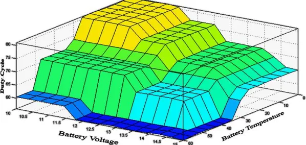
Figure 7 below shows a 3D surface plot of the system output. Battery voltage and temperature are plotted on the width and dept axis while duty cycle is represented on the height of the cuboid. At low temperature range the battery is charged with higher initial current (high duty cycle). As the temperature increases the system automatically modifies the charging pattern to compensate for the rise in temperature. If certain abnormally high battery temperatures is reached, the system practically shuts down the charging process, to allow the battery cool down.
Figure 7 MATLAB Surface plot of the battery voltage and temperature against duty cycle
As seen in table 1 above, duty cycle can vary from a low 53% to a maximum of 84%, totally dependent on the values of the three monitored parameters of the battery. From the 3D surface in figure 7 above, notice that as the battery voltage increases during charge process, the system duty cycle is reduced taking into consideration current battery temperature. The plot shows that normal charging terminates at a float voltage only if the temperature is low or normal.
ISSN(Online) : 2319-8753 ISSN (Print) : 2347-6710
I
nternational
J
ournal of
I
nnovative
R
esearch in
S
cience,
E
ngineering and
T
echnology
(An ISO 3297: 2007 Certified Organization)
Website: www.ijirset.com
Vol. 6, Issue 6, June 2017
As battery voltage increases the duty cycle reduces. Notice that the battery is allowed to charge at floating level if the current being drawn is low. Again, this output is not independent of the battery temperature.
Figure 9 MATLAB Surface plot of the battery temperature and Charging Current against duty cycle
In figure 9 above, the charging current and battery temperature is plotted against duty cycle to show how the duty cycle is adjusted with changes in charging current and battery temperature. Notice that high duty cycled (which is same as high charging current) is allowed only at lower range of battery temperature.
Should the charging current start increasing at high battery temperature the duty cycle is reduced automatically to save the battery.
4.1 Result from Prototype: The fuzzy control module was coded in C language using Microchip MPLAB IDE and compiled with HI-TECH C® for PIC10/12/16. The developed prototype was tested for conformity with design parameters and energy transfer efficiency. The result showed positive conformity with the design. An average energy transfer efficiency of 76% was recorded.
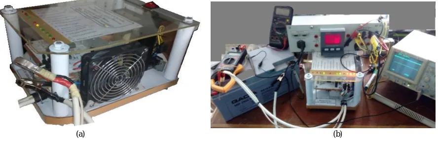
(a) (b)
Figure 10 (a) Picture of the Embedded Fuzzy Logic Charger Controller implemented (b) a Picture of the Prototype charging a lead acid battery while an energy analyser, clamp meter, Oscilloscope and multimeter are uses to log its energy transfer.
V. CONCLUSION
Owing to the gaps that exist in the development of this relatively new technology (fuzzy logic control of battery chargers) and the peculiarity of Nigerian society and many African societies, adoption and commercialization of the demonstrated system in Nigeria will prove to be economically viable, as it can increase local availability of low cost high quality battery chargers and possibly the life span of lead acid battery that employ its use.
REFERENCES
[1] Zadeh, Lotfi A. "Fuzzy logic: issues, contentions and perspectives." In Acoustics, Speech, and Signal Processing, 1994. ICASSP-94., 1994 IEEE International Conference on, vol. 6, pp. VI-183. IEEE, 1994..
[2] Huang, Cong-Hui, Chung-Chi Huang, Ting-Chia Ou, Kai-Hung Lu, and Chih-Ming Hong. "Intelligent fuzzy logic controller for a solar charging system." In Advanced Intelligent Mechatronics, 2009. AIM 2009. IEEE/ASME International Conference on, pp. 1412-1417. IEEE, 2009.
[3] Swathika, R., RK Ganesh Ram, V. Kalaichelvi, and R. Karthikeyan. "Application of fuzzy logic for charging control of lead-acid battery in stand-alone solar photovoltaic system." In Green Computing, Communication and Conservation of Energy (ICGCE), 2013 International Conference on, pp. 377-381. IEEE, 2013.
[4] Sánchez, Alberto. "Implementation of intelligent controller for battery charging applications." Master's thesis, University of Bradford/2000, 2000.
[5] LaMeres, Brock J., and M. H. Nehrir. "Design And Implementation Of A Fuzzy Logic-Based Voltage Controller For Voltage Regulation Of A Synchronous Generator." IEEE Computer Applications in Power 19, no. 4, 2117-2118, 2004.
[6] Farkas, Ferenc, and Sándor Halász. "Embedded Fuzzy Controller for Industrial Applications." Acta Polytechnica Hungarica 3, no. 2: 41-63 (2006).