IJEDR1603120
International Journal of Engineering Development and Research (www.ijedr.org)730
An Efficient Algorithm Image Processing Technique
Using Bilateral Filtering Method
Rachita Kansal, Bhumika Garg
1Research scholar, 2Assistant Professor, 1Department of Computer Science Engineering1Modern Institute of Engineering & Technology , Ambala, India
________________________________________________________________________________________________________
Abstract - A new and efficient algorithm for high-density salt and pepper noise removal in images and videos is proposed. The existing non-linear filter like Standard Median Filter (SMF), Adaptive Median Filter (AMF), Decision Based Algorithm (DBA) and Robust Estimation Algorithm (REA) shows better results at low and medium noise densities. At highnoise densities, their performance is poor. A new algorithm to remove high-density salt and pepper noise using modified sheer sorting method is proposed. The new algorithm has lower computation time when compared to other standard algorithms. Results of the algorithm is compared with various existing algorithms and it is proved that the new method has better visual appearance and quantitative measures at higher noise densities as high as 90%.
Index Terms - Image Processing,Color Image,Image Filtering ,Hybrid Filter
________________________________________________________________________________________________________
I.INTRODUCTION
Computer image processing methods mainly take two categories. First, the space domain processing; that is in the image
space of the image processing. The other is the image spatial domain. It should be use frequency domain through the orthogonal transformation in various frequency domain. Next, do reversal processing further and then it can be finish processing for ima ge. It is also based on the actual characteristics of the image, noise and spectral distribution of the demographic characteristics of the law. Scientists derived many de-noising approaches. One of the most intuitive ways of noise energy is generally concentrated in high-frequency and spectral images located in a limited range of this characteristic. And then low-pass filtering approach is used to de-noising or smoothing the image processing. This is the first class of image processing methods. Another way is processing in the frequency domain. (such as: Fourier transform, wavelet transform.) Image denoising is often used in the field of photography or publishing where an image was somehow degraded but needs to be improved before it can be printed. For this type of application we need to know something about the degradation process in order to develop a model for it. When we have a model for the degradation process, the inverse process can be applied to the image to restore it back to the original form. This type of image restoration is often used in space exploration to help eliminate arte facts generated by mechanical jitter in a spacecraft or to compensate for distortion in the optical system of a telescope. Image denoising finds applications in fields such as astronomy where the resolution limitations are severe, in medical imaging where the physical requirements for 2 high quality imaging are needed for analyzing images of unique events, and in forensic science where potentially useful photographic evidence is sometimes of extremely bad quality [1].Colour images are considered as three band monochrome images, where each band is of a different colour. Each band provides the brightness information of the corresponding spectral band. Typical colour images are red, green and blue images and are also referred to as RGB images. This is a 24 bits/pixel image. There are various methods to help restore an image from noisy distortions. Selecting the appropriate method plays a major role in getting the desired image. The de noising methods tend to be problem specific. For example, a method that is used to de noise satellite images may not be suitable for de noising medical images. In order to quantify the performance of the various de noising algorithms, a high quality image is taken and
some known noise is added to it. This would then be given as input to the de noising algorithm, which produces an image close to the original high quality image. In case of image de noising methods, the characteristics of the degrading system and the noises are assumed to be known beforehand. The image s(x, y) is blurred by a linear operation and noise n(x, y) is added to
IJEDR1603120
International Journal of Engineering Development and Research (www.ijedr.org)731
2.2 Hybrid FilteringNoise is the most annoying problem[3] in image processing. One way to get rid of this problem is the development of such a robust algorithm that can perform the processing tasks in presence of noise. The other way is to design a filtration process to eliminate the noise from images while preserving its features, edges and details. Noise introduces random variations into image that fluctuate the original values to some different values. Causes which may introduce noise to images include flaws in data transmission, imperfect optics, sensor malfunctioning, processing techniques and electronic interference .Mathematical morphology is a methodology specifically designed for the analysis of geometrical structures in an image by probing it with small patterns called structuring elements. The resultant image operators are nonlinear and found useful for many applications like edge detection object segmentation, noise suppression and exploring geometrical structures of images. Alternate sequence filters (ASFs) are recognized as one of these important operators and have been widely used and researched.
2.3 Sharpening Filters: The sharpening method highlight fine details in an image or it can enhance the detail of image which is blurred by the noise. Hence visibility of image can be improved by using sharpening technique. As image blurring is achieved by using averaging filters hence sharpening can be achieved by using operators that invert averaging operators. In mathematics averaging is equivalent to the concept of integration and to inverts integration differentiation is used. Hence sharpening filters can be represented by using partial derivatives. Laplacian Filtering is an image sharpening technique. Unsharp Masking (UM) and High boost filtering are most commonly used filtering techniques used for image sharpening. Histogram processing can also be used for image enhancement. Inhistogram processing normalization of image histogram is done which makes it as flat as possible. A such kind of technique of image sharpening is Histogram Equalization (HE). UM and HE techniques of image sharpening are discussed below:
a) Unsharp Masking
Unsharp masking is an efficient technique for the sharpness enhancement. It sharpen the edges in the image by subtracting an unsharp or smoothed version of an image from the original image. The basic procedure followed in unsharp masking is show below:
Unsharp masking produces an edge image g(x,y) from an input image f(x,y) g(x,y) = f(x,y) - (x,y) Eq.(2.1 )
Where (x,y) is a smoothed version of f(x,y).
The fig. below shows the unsharp masking filter algorithm:
IJEDR1603120
International Journal of Engineering Development and Research (www.ijedr.org)732
Fig.2.2 Calculating the Unsharp mask.Now if the edge image which is calculated in above figure is added to the original image it will sharpen the original image as follows:
Fig.2.3 Sharpening of original image using Unsharp mask. Now the equation will become as:
(x,y) = f(x,y) + k*g(x,y) Eq. (2.2)
iii.Proposed Method
Removing or reducing impulse noise is a very active research area in image processing. Impulse noise is caused by errors in the data transmission generated in noisy sensors or communication channels, or by errors during the data capture from digital cameras. Noise is usually quantified by the percentage of pixels which are corrupted. Corrupted pixels are either set to the maximum value or have single bits flipped over. In some cases, single pixels are set alternatively to zero or to the maximum value. This is the most common form of impulse noise and is called salt and pepper noise. Nevertheless other types of impulse noise are possible as well.
The detailed operation of our proposed method for the removal of salt and pepper noise from images shown. The stepwise operation of proposed method is as follows:
(i) Read the noisy image which is corrupted with salt and pepper noise. (ii) Select a 2D window of size 3 3. Assume that the processing pixel is
(iii) If then is a noise free pixel and will be left unchanged. (iv) If or 255 then is noisy pixel. Hence two cases will be possible:
Case (i): If selected window contain all values as 0 and 255 then replace with mean of values in selected window. Case (ii): If selected window also contains values other than 0 and 255 then apply the TMASBF on the processing pixel.
(v) The output will be the denoised image . Algorithmic Design
1. Read color noise image.
2. Separate the three plane of color of color image i.e. red-green-blue plane. 3. Select either of the planes(R/G/B).
4. Select 2-D window of size 3×3. Assume that the pixel being processed is Pij.
5. If the processing pixel has values either greater than 0 and less than 255 i.e. 0<Pij<255 then Pij is an uncorrupted pixel and its value is left unchanged.
6. If Pij=0 or Pij=255 then it is a corrupted pixel and further proceeding is based on following conditions
7. Case i): If the selected window contains all the elements as 0’s and 255’s. Then replace with the mean of the element of window.
8. Case ii): If the selected window contains not all elements as 0’s and 255’s. Then eliminate 255 and 0’s and find the median value of the remaining elements. Replace with the median value.
9. Repeat steps 4 to 6 until all the pixels in the entire plane are processed. 10. Go to step 3 and Select next plane.
IJEDR1603120
International Journal of Engineering Development and Research (www.ijedr.org)733
Step-2 Separate the three plane of color of color image i.e. red-green-blue plane.Step3 Load the Distorted grayscale image Leena, Babon,Peepers,Boat of at the nose density level 0.9 ,we may include this density level 0.1 to 0.9. In this work we use the maximum density level of noise, through which we easily check the performance of the our filters ,and also calculate the image matrices like, PSNR,IEF,MSE
IJEDR1603120
International Journal of Engineering Development and Research (www.ijedr.org)734
Step 5 : filtered image by Hybrid FilterStep 6 : filtered image by Purposed Filter
Table No-5.1 Comparative analysis of Image Metric parameter(PSNR) using different filter
Density level PSNR by
Adaptive filter
PSNR by
Hybrid filter
PSNR by
conventional filter
PSNR by
Trimmed filter
PSNR by
DBA Filter
PSNR by
Purposed Filter
0.9 5.3442 5.8275 7.7313 15.7821 18.3642 30.4421
0.8 5.3006 5.8192 9.0932 19.7079 20.6720 35.4012
IJEDR1603120
International Journal of Engineering Development and Research (www.ijedr.org)735
010
0.9 0.8 0.7 0.6 0.3 0.1
Noise Densities
AF
Purposed
HF
Fig. 5.1PSNR By Different Filter
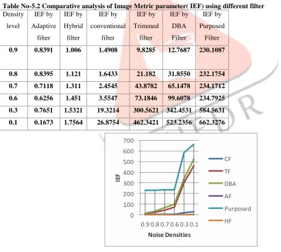
Table No-5.2 Comparative analysis of Image Metric parameter( IEF) using different filter Density level IEF by Adaptive filter IEF by Hybrid filter IEF by conventional filter IEF by Trimmed filter IEF by DBA Filter IEF by Purposed Filter 0.9 0.8391 1.006 1.4908 9.8285 12.7687 230.1087
0.8 0.8395 1.121 1.6433 21.182 31.8550 232.1754
0.7 0.7118 1.311 2.4545 43.8782 65.1478 234.1712
0.6 0.6256 1.451 3.5547 73.1846 99.6078 234.7925
0.3 0.7651 1.5321 19.3214 300.5621 342.4531 584.5631
0.1 0.1673 1.7564 26.8754 462.3421 523.2356 662.3276
0 100 200 300 400 500 600 700
0.9 0.8 0.7 0.6 0.3 0.1
IE F Noise Densities CF TF DBA AF Purposed HF
Fig. 5.2 IEF By Different Filter
IJEDR1603120
International Journal of Engineering Development and Research (www.ijedr.org)736
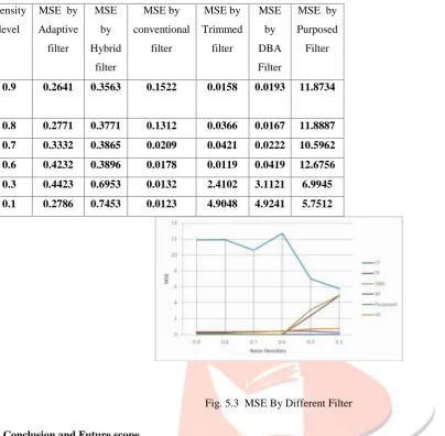
Densitylevel
MSE by Adaptive filter MSE by Hybrid filter MSE by conventional filter MSE by Trimmed filter MSE by DBA Filter
MSE by Purposed Filter
0.9 0.2641 0.3563 0.1522 0.0158 0.0193 11.8734
0.8 0.2771 0.3771 0.1312 0.0366 0.0167 11.8887
0.7 0.3332 0.3865 0.0209 0.0421 0.0222 10.5962
0.6 0.4232 0.3896 0.0178 0.0119 0.0419 12.6756
0.3 0.4423 0.6953 0.0132 2.4102 3.1121 6.9945
0.1 0.2786 0.7453 0.0123 4.9048 4.9241 5.7512
Fig. 5.3 MSE By Different Filter
v. Conclusion and Future scope
An efficient non-linear algorithm to remove high- salt and pepper noise is proposed. The modified sheer architecture reduces the computational time required for finding the median. This increases the efficiency of the system. The algorithm removes noise even at higher noise densities and preserves the edges and fine details. The performance of the algorithm is better when to the other architecture of this type.
REFERENCES
[1]A. G Rose, M. Kube, P. Schmitt, R. Weigeland R. Rose(2011), “Image Denoising Using Bilateral Filter With Noise-Adaptive Parameter Tuning,” Fraunhofer Institute for Integrated Circuits, D-91058 Erlangen, Germany.
[2]S. Esakkirajan, T. Veerakumar “Removal of High Density Salt and Pepper Noise Through Modified Decision Based Unsymmetric Trimmed Median Filter” IEEE SIGNAL PROCESSING LETTERS, VOL. 18, NO. 5, MAY 2011 pp;287-290. [3] Isma Irum“ A Nonlinear Hybrid Filter for Salt & Pepper Noise Removal from Color Images” Comsats Institute of Information Technology Vol.13,February 2015 pp;79-86.
[4]Rafael C. Gonzales and Richard E. Woods,“Digital Image Processing,” 3rd edition, 2011. C. H. Lin, J. S. Tsai, and C. T. Chiu (2010), “Switching Bilateral filter with a Texture/Noise Detector for Universal Noise Removal,” IEEE Trans. On.Image Processing, vol. 19, pp.2307-2320, Sept. 2010.
[5]C. Shyam Anand and J. S. Sahambi (2009), “MRI Denoising Using Bilateral Filter in Redundant Wavelet Domain,” IIT Guwahati, India, 2009.
[6] C. Tomasi and R. Manduchi (1998), “Bilateral filtering for gray and color images,” in Proc. ICCV pp.839–846 Bombay, 1998.
[7] D. Duan, Qian Mo, Y. Wan and Z. Han (2010), “A Detail Preserving Filter for Impulse Noise Removal,” International Conference on ComputerApplication and System Modeling (ICCASM), 2010.