Abstract
This paper presented a new image fusion based on compressed sensing (CS). The method decomposes two or more original images using directionlet transform, gets the sparse matrix by the directionlet coefficient sparse representation, and fuses the sparse matrices with the coefficient absolute value maximum scheme. The
compressed sample can be obtained through random observation. The fused image is recovered from the reduced samples by solving the optimization. The study demonstrates that the compressive sensing image fusion algorithm based on directionlets has a number of perceived advantages. The simulations show that the proposed algorithm has the advantages of simple structure and easy implementation and also can achieve a better fusion performance.
Keywords:Image fusion; Compressive sensing; Directionlet transform
1. Introduction
The main goal of image fusion is to extract all the import-ant features from all input images and integrate them to form a fused image which is more informative and suitable for human visual perception or computer processing.
There are a number of pixel-level image fusion methods, including the weighted average method [1,2], the pyramid transform method [3], principal component analysis (PCA) method [4], as well as fusion based on wavelet transform methods. The wavelet transform has become an important tool in image fusion method for its excellent feature of time-frequency analysis [5]. However, wavelet bases are isotropic and of limited directions and fail to represent high anisotropic edges and contours in images well. For the drawbacks of the wavelet transform, direc-tionlet transform is an anisotropic transform proposed by Vladan, which is based on the integer lattice. The direc-tionlet still uses the one-dimensional filter group, but with the base function of multi-directional anisotropy, the directionlet has a detachable filter and critical structure and is able to be fully reconstructed. Thus, theoretically, it has more advantages than the general wavelet transform and the other second-generation wavelet transform [6].
In recent years, inspired by the ideas of‘sparse’ approxi-mation, a novel theory called compressed sensing (CS) has
been developed [7-9]. The CS principle claims that if a sig-nal is compressive or sparse in a certain transform do-main, it can be projected onto a low-dimensional space using a measurement matrix which is irrelevant with transform basis while still enabling reconstruction at high probability from these small numbers of random linear measurements via solving an optimization problem. Therefore, it is expected to provide a new idea for image fusion by combined directionlets with CS.
This article proposes a new scheme for image fusion; in our scheme, directionlet transform first decomposes each source image into two components, i.e., dense and sparse components. Then, the dense components are fused by the selection method according to the manifes-tations of defocus, while the sparse components are fused under the frame of CS via fusing a few linear measurements by solving the problem of l1 norm minimization which is based on the two-step iterative shrinkage reconstruction algorithm. The proposed fu-sion scheme is applied to infrared and visible image fusion experiments, and the performance is evaluated in terms of computational efficiency, visual quality, and quantitative criterion.
The test results show that it can blend the edges of the image information fairly well, and subjectively more in line with human visual characteristics and the object-ive evaluation is also superior to other image fusion methods.
* Correspondence:[email protected]
College of Electronics and Communication Engineering, Tianjin Normal University, Tianjin 300387, China
2. Directionlet transform
The directionlet transform proposed by the German researcher Vladan is the multi-directional anisotropy based upon the integer lattice [10-12]. It adopts multi-directional anisotropy basis functions; therefore, it has more advantages in expressing the image than the aver-age wavelet transform. At the same time, it only uses the one-dimensional filter banks with separable filtering and critical structures and can be reconstructed totally; thus, as far as the computational complexity is concerned, it has more advantage than the other second-generation wavelet transform. The directionlet transform is a new multi-scale analysis tool.
When using one-dimensional filter banks to conduct multi-directional two-dimensional separable wavelet trans-form, we select any two rational slope r1=b1/a1 and r2=b2/a2's digital line direction to filtering and
down-sampling; however, when the critical sampling is enhanced, two digital lines will have the issue of direction of mutual inductance, that is, along the sloper1and r2, the concept of the digital line cannot provide a systematic rule for the down-sampling of the repeated filtering and repeated sampling.
Therefore, Vladan has proposed the multi-directional filtering and down-sampling which are based on the lat-tice. First, chose any two reasonable slopes r1=b1/a1and r2=b2/a2's directions in grid spacez2, expressed in matrix as
MΛ¼ aa1 b1 2 b2
¼ d1 d2
;a1;a2;b1;b2∈Z;n1≠n2: ð1Þ
The direction along the slope r1 of the vector r1 is called the change of direction; the direction along the slope r2 of the vector d2 is called the queue direction. Figure 1Based on the integer lattice filtering and down-sampling. (a)Expressed with the generator matrix;(b)two-dimensional
dual-channel filter.
ticeΛand the matrix generated accordingly. Thereout, the sparse representation of the anisotropic object on the direc-tion of the image can be obtained. The principle is shown in Figure 1 (the change of direction in the figure is 45°).
The image which has gone through the above men-tioned directionlet transform has a very sparse coeffi-cient and then can obtain more directional information, which can be better used to describe the edge contour of the infrared image.
3. Compressive sensing and image fusion
Compressive sensing enables a sparse or compressible signal to be reconstructed from a small number of non-adaptive linear projections, thus significantly reducing the sampling and computation costs [13]. CS has many promising applications in signal acquisition, compres-sion, and medical imaging. In this paper, we investigate its potential application in the image fusion.
As far as a real-valued finite-length one-dimensional discrete-time signalxis concerned, it can be viewed as a RN space N× 1 dimensional column vector, and the element isx[n],n= 1, 2,…,n. If the signal is sparseK, it can be shown as the following formula:
x¼ψs; ð2Þ
whereψis theN×Nmatrix andsis the coefficient com-ponent column vector of dimensionN× 1.
When the signal x in the base ofψ has only non-zero coefficients of K< <N(or greater than zero coefficients), ψis called the sparse base of the signalx. The CS theory indicates that if the signalx's (the length isN) transform coefficient which is at an orthogonal basisψis sparse (that is, only a small number of non-zero coefficients can be ob-tained), if these coefficients are projected into the meas-urement basicϕwhich is irrelevant to the sparse base ψ, the M× 1 dimensional measurement signal y can be ob-tained. By this approach, the signal x's compressed sam-pling can be realized. The expression can be expressed as
y¼ϕx¼ϕψs¼Θs; ð3Þ
where ϕ is the measurement matrix of M×N and Θ=
ϕψis theM×Nmatrix and called the projection matrix. y is the measurement value of the projection matrix Θ,
which is relevant to the sparse signal s. Only when the orthogonal basis ψ is irrelevant to the measurement matrixϕ, that is to say, the projection matrix can satisfy the requirement of restricted isometry property (RIP), the signal x can be accurately recovered via these mea-sured value by solving formula (3) in the best optimized way. The block diagram derived from the CS theory for the field of image processing is shown in Figure 1.
min
s k ks l1; s:t: y¼ϕψs: ð4Þ
The advantage that the CS theory has is that the data obtained via the projection measurement is much smaller than the conventional sampling methods, break-ing the bottleneck of the Shannon samplbreak-ing theorem, so that the high-resolution signal acquisition becomes pos-sible. The attraction of CS theory is that it is for applica-tions in many fields of science and engineering and has important implications and practical significance, such as statistics, information theory, coding theory, com-puter science theory, and other theories.
Compared with the traditional fusion algorithms, the CS-based image fusion algorithm theory has shown sig-nificant superiority: the image fusion can be conducted in the non-sampling condition of the image with the CS technique, the quality of image fusion can be improved by increasing the number of measurements, and this
algorithm can save storage space and reduce the compu-tational complexity. The main ideas of the CS-based image fusion algorithm theory are as follows: first of all, the two images which need to deal with should undergo the directionlet transform, the sparse matrix can be ob-tained after the directionlet coefficients are processed with the sparse treatment, then the fusion rules for the sparse matrix integration are determined, compressive sampling through random sampling matrix is obtained, and finally, the fused image can be obtained in the best optimized way. The practical function of wavelet transform is the sig-nal decorrelation, and all the information of the sigsig-nal are concentrated into the wavelet coefficients with large amplitude. These large wavelet coefficients contain far more energy than that contained in small coefficient so that in the reconstruction of the signal, a large coeffi-cient is more important than the smaller one.
This paper adopted the fusion rule which concentrated on the larger absolute value; comparing two wavelet co-efficients of the same location in two images, the greater absolute value is selected as the fusion wavelet coeffi-cient. The expression is as follows:
Df ¼DM andM¼arg maxi¼1;ð2j jD;…iÞ;I ð5Þ
where Df is the fusion wavelet coefficient, DM is the
wavelet coefficient whose absolute value is the largest of
the wavelet coefficients in the same location in different images, andIis the number of the source image.
The directionlet transform is used to deal with the source image; directionlet coefficients are obtained with the sparse treatment: the small coefficient (or coefficient of close to zero) is set to zero to obtain an approximate sparse coefficient matrix.
When the source image is conducted via sparse trans-formation, the wavelet is used as the sparse basis. To reconstruct the image with less measurement value, we must ensure that the sparse basisψand the measurement Figure 4Multi-focus image fusion experiment. (a)In-focus image,(b)far-focus image,(c)DWT, and(d)CS.
2. The directionlet coefficients are processed with the sparse treatment and then fused according to the larger absolute value rule.
3. For the fused directionlet coefficients, the random matrix is selected as the measurement matrixϕ; after the measurement, the measured valueycan be obtained.
4. By solving the linear programming of thel1norm, the approximate solution^xcan be acquired. 5. Conduct the inverse transform to the obtained
directionlet coefficients and thus the fusion image can be acquired.
4. Experimental results and analysis
The experiments selected the infrared and visible registra-tion images to conduct the fusion experiment with differ-ent approaches. Figure 2 shows image (a) and image (b) which respectively represent the infrared and visible images of the airfield, and the two images contain much detail and texture information. Image (c) represents the fusion result based on the Laplacian pyramid transform, image (d) represents the fusion result based on the fusion of the discrete wavelet transform, and image (e) represents the fusion results based on CS. As can be seen from the figure, images (c) and (d) have different degrees of blur. Compared to images (c) and (d), image (e) is clearer as far as the visual effect is concerned.
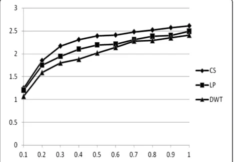
Table 1 is an objective evaluation towards the quality of the images in this set of experiments. As can be seen from the table, the standard deviation and the average gradient of image (e) are the highest, which demonstrate that the image has better contrast and sharpness, and therefore is consistent with the subjective evaluation re-sults. Figure 3 is the mutual information of different sampling rates for infrared and visible image fusion. The mutual information value shows the similarity between the fusion image and the source image. The sampling rate is associated with the fusion image quality [14]. The sam-pling rate is higher, and the fusion image quality is better; however, the cost of operation of the reconstructed image is larger, and the required storage space is bigger.
As can be seen from Figure 3, the mutual information values of the compressive sensing image fusion algo-rithm are the best among the three fusion methods.
ing image fusion algorithm are the best among the three fusion methods.
5. Conclusions
The paper put forward a fusion algorithm based on the compressed sensing. Compared with the traditional wave-let transform, the proposed CS-based image fusion algo-rithm can preserve the image feature information, enhance the fused image space detail representation ability, and im-prove the fused image information. The experiment im-proves that the approach in this paper is better than the wavelet transform and Laplace pyramid decomposition, etc.
Competing interests
The authors declare that they have no competing interests.
Acknowledgements
The authors are grateful to the anonymous referees for the constructive comments.
Received: 30 December 2013 Accepted: 24 January 2014 Published: 1 February 2014
References
1. X Zhou, R-A Liu, J Chen, Infrared and visible image fusion enhancement technology based on multi-scale directional analysis. IEEE Computer Society, (IEEE, Piscataway, 2009)
2. DL Hall, J Linas, An introduction to multisensor data fusion. Proceedings of the IEEE85(10), 6–23 (1997)
3. A Toet, LJ van Ruyven, JM Velaton, Merging thermal and visual images by a contrast pyramid. Optical Engineering28(7), 789–792 (1989)
4. J Yonghong, Fusion of landsat TM and SAR images based on principal component analysis. Remote Sensing Technology and Application
13(1), 4649–4654 (1998)
5. YC Lin, QH Liu, An image fusion algorithm based on directionlet transform. Nanotechnology and Precision Engineering8(6), 565–568 (2010) 6. V Velisavljevic, B Beferull-Lozano, M Vetterli, Directionlets: anisotropic
multi-directional representation with separable filtering. IEEE Transactions on Image Processing15(7), 1916–1933 (2006)
7. F Jin Wei, YM Ran-di, Multi-focus fusion using dual-tree contourlet and compressed sensing. Opto-Electronic Engineering38(4), 87–94 (2011) 8. E Candes, MB Wakin, An introduction to compressive sampling. IEEE Signal
Processing Magazine48(4), 21–30 (2008)
9. F Provost, F Lesage, The application of compressed sensing for photo-acoustic tomography. IEEE Trans. on Med. Imaging28(4), 585–594 (2009) 10. V Velisavljevic, Low-complexity iris coding and recognition based on
directionlets. IEEE Transactions on Information Forensics and Security
4(3), 410–417 (2009)
11. V Velisavljevic, B Beferull-Lozano, M Vetterli, Space-frequency quantization for image compression with directionlets. IEEE Transactions on Image Processing16(7), 1761–1773 (2007)
13. T Wan, N Canagarajah, A Achim, Compressive image fusion. IEEE International Conference on Image Processing, (IEEE, Piscataway, 2008), pp. 1308–11
14. XS Huang, QF Dai, YQ Cao, Compressive sensing image fusion algorithm based on wavelet sparse basis. Application Research of Computers
29(9), 3581–3583 (2012)
doi:10.1186/1687-1499-2014-19
Cite this article as:Zhouet al.:Compressive sensing image fusion algorithm based on directionlets.EURASIP Journal on Wireless Communications and Networking20142014:19.
Submit your manuscript to a
journal and benefi t from:
7Convenient online submission
7Rigorous peer review
7Immediate publication on acceptance
7Open access: articles freely available online
7High visibility within the fi eld
7Retaining the copyright to your article