Electronic Thesis and Dissertation Repository
8-20-2013 12:00 AM
Electrochemical Evaluation of Ionic Liquids for Biphasic
Electrochemical Evaluation of Ionic Liquids for Biphasic
Extraction of Metal Ions Common to Spent Nuclear Fuel
Extraction of Metal Ions Common to Spent Nuclear Fuel
Thomas J. Stockmann
The University of Western Ontario
Supervisor Dr. Zhifeng Ding
The University of Western Ontario Graduate Program in Chemistry
A thesis submitted in partial fulfillment of the requirements for the degree in Doctor of Philosophy
© Thomas J. Stockmann 2013
Follow this and additional works at: https://ir.lib.uwo.ca/etd
Part of the Analytical Chemistry Commons, and the Physical Chemistry Commons
Recommended Citation Recommended Citation
Stockmann, Thomas J., "Electrochemical Evaluation of Ionic Liquids for Biphasic Extraction of Metal Ions Common to Spent Nuclear Fuel" (2013). Electronic Thesis and Dissertation Repository. 1540.
https://ir.lib.uwo.ca/etd/1540
This Dissertation/Thesis is brought to you for free and open access by Scholarship@Western. It has been accepted for inclusion in Electronic Thesis and Dissertation Repository by an authorized administrator of
Extraction of Metal Ions Common to Spent Nuclear Fuel
(Thesis format: Integrated-Article)
by
Thomas J. Stockmann
Graduate Program in Chemistry
A thesis submitted in partial fulfillment of the requirements for the degree of
Doctor of Philosophy
The School of Graduate and Postdoctoral Studies The University of Western Ontario
London, Ontario, Canada
ii
to observe and quantify simple ion transfer (IT) as well as ligand assisted, or facilitated ion transfer (FIT) reactions. Liquid|liquid electrochemistry has developed to where valuable thermodynamic constants – for example, the metal ion to ligand stoichiometry and overall complexation constant, β, in FIT - can be evaluated using cyclic voltammetry (CV). Recently, ionic liquids (ILs) have shown greater metal ion extraction efficiencies in water-IL biphasic separations relative to conventional molecular organic solvents. In this way, they are of interest to the nuclear industry for applications in spent nuclear fuel (sometimes called nuclear waste) recycling. Herein, liquid|liquid electrochemistry has been used to investigate FIT of metal ions typically found in SNF at traditional water|organic solvent (w|o) and novel water|ionic liquid (w|IL) interfaces.
Initially, the hydrophobicity of 8 commercially available ILs were evaluated and the data obtained, combined with valuable insight from the literature, was used to select the cation and anion components of an IL that was prepared in-house; trihexyltetradecylphosphonium tetrakis(pentafluorophenyl)borate (P66614TB). P66614TB
possessed a suitable w|IL polarizable potential window of ~0.9 V – comparable to other ILs found in the literature, but at a cost 10× cheaper than that found commercially.
The formal ion transfer potential, '
z
w o IL i
, of metal ions is a point of reference for
electrochemically induced FIT and was evaluated for the first time at a w|IL interface.
The alkali metals Li+, Na+, K+, Rb+, and Cs+ where found to have '
z
w o IL i
equal to 0.565,
0.548, 0.521, 0.531, and 0.518 V, respectively, which agrees well with the trend of increasing atomic radius and thus increasing hydrophobicity.
With a suitable IL in hand, FIT of UO22+, Sr2+, Rb+, and Cs+ were examined at w|o
and w|IL micro-interfaces. Ligands for contemporary SNF recycling, such as octyl(phenyl)-N,N-diisobutylcarbamoyl-methylphosphine oxide (CMPO) were employed. The w|IL interface demonstrated overall complexation constants, β, several orders of magnitude higher than that observed at w|o interface. For example, [SrCMPO3]+ had β
iii
ion transfer ● equilibrium complexation stoichiometry and constants ● interface between two immiscible electrolytic solutions (ITIES) ● hydrophobicity and hydrophilicity ● ionic
iv
6.1, 6.2, 6.3, 6.5, 7.1, 7.2, and 7.3, while Chapters 2, 6.4, and 6.5 represent manuscripts submitted and in-preparation. Below is a list, by chapter, of the co-authors and their contributions.
Chapter 2: T.J. Stockmann and Z. Ding, In-preparation (2013). Experimental approach and design were proposed by ZD. TJS performed experiments, analyzed data, and wrote the manuscript. The manuscript was edited and finalized by ZD.
Chapter 3 appears in T.J. Stockmann, Z. Ding, J. Electroanal. Chem. 649 (2010) 23-31. ZD proposed experimental design and developed the computational code. TJS performed electrochemical experiments, performed computational analysis, analyzed data, and wrote the manuscript. The manuscript was edited and finalized by ZD. Reprinted with permission, copyright 2013 Elsevier.
Chapter 4.1 appears in T.J. Stockmann, J. Zhang, J.C. Wren, Z. Ding, Electrochim. Acta 62 (2012) 8-18. Experimental design/approach developed by TJS and ZD. Electrochemical experiments, synthesis, and materials characterization performed by TJS and JZ. TJS performed data analysis and wrote the manuscript. The manuscript was edited and finalized by ZD. Reprinted with permission, copyright 2013 Elsevier.
Chapter 4.2 appears in T.J. Stockmann, Z. Ding, J. Phys. Chem. B 116 (2012) 12826-34. Experimental design/approach developed by TJS and ZD. Electrochemical experiments, synthesis, and materials characterization performed by TJS. TJS performed data analysis and wrote the manuscript. The manuscript was edited and finalized by ZD. Reprinted with permission, copyright American Chemical Society (2013).
Chapter 5: T.J. Stockmann, R. Guterman, P.J. Ragogna, and Z. Ding, In preparation (2013). Experimental design and approach proposed by TJS, RG, and ZD. Synthesis and materials characterization performed by RG. Electrochemical analysis performed and data analyzed by TJS. TJS wrote the manuscript. The manuscript was edited by RG, PJR, and ZD, and finalized by ZD.
Chapter 6.1 appears in T.J. Stockmann, A.-M. Montgomery, Z. Ding, J. Electroanal. Chem. 684 (2012) 6-12. Experiment proposed by TJS, AMM, and ZD. TJS and AMM performed electrochemical experiments and analyzed the data. The manuscript was written by TJS; edited and finalized by ZD. Reprinted with permission, copyright 2013 Elsevier.
v
HHG and ZD. Electrochemical experiments performed by TJS and AJO. Data analysis was performed by TJS, AJO, and MAM. TJS and AJO wrote the manuscript, which was edited by HHG and ZD. ZD finalized the manuscript. Reprinted with permission, copyright © 2011 WILEY-VCH Verlag GmbH & Co. KGaA, Weinheim. http://dx.doi.org/10.1002/elan.201100401.
Chapter 6.4: T.J. Stockmann, D. Momotenko, H.H. Girault, and Z. Ding, In preparation (2013). Experimental design developed by TJS, HHG, and ZD. Computational code developed by TJS and DM. Data analysis performed by TJS. TJS wrote the manuscript which was edited by DM, HHG, and ZD.
Chapter 6.5 appears in T.J. Stockmann, Z. Ding, Phys. Chem. Chem. Phys. 14 (2012) 13949-54. Experiment designed by ZD. Experimental approach and computational code developed, and data analyzed by TJS. TJS wrote the manuscript, which was edited and finalized by ZD. Reproduced by permission of the PCCP Owner Societies (2013). http://dx.doi.org/10.1039/C2CP42107K.
Chapter 7.1 appears in T.J. Stockmann, Z. Ding, Anal. Chem. 83 (2011) 7542-9. Experiment designed by ZD. TJS performed electrochemical experiments, analyzed data, and wrote the manuscript. Manuscript was edited and finalized by ZD. Reprinted with permission, copyright American Chemical Society (2013).
Chapter 7.2 appears in T.J. Stockmann, Y. Lu, J. Zhang, H.H. Girault, Z. Ding, Chem. Eur. J. 17 (2011) 13206-16. Experiment designed by HHG and ZD. Electrochemical experiments performed and data analyzed by TJS. Mass spectroscopic experiments performed and data analyzed by TJS and YL . TJS and YL wrote the manuscript that was edited by HHG and ZD. ZD finalized the manuscript. Reprinted with permission, copyright © 2013 WILEY-VCH Verlag GmbH & Co. KGaA, Weinheim. http://dx.doi.org/10.1002/chem.201102491
Chapter 7.3 appears in T.J. Stockmann, A.-M. Montgomery, Z. Ding, Anal. Chem. 84 (2012) 6143-9. Experiment designed by TJS and ZD. Electrochemical experiments performed and data analyzed by TJS and AMM. TJS wrote the manuscript. Manuscript edited and finalized by ZD. Reprinted with permission, copyright American Chemical Society (2013).
vi
nature and dedication to science will always be an example and an ideal which I will endeavor to achieve. It may be said - and probably has - that he took me from nothing and raised me up.
I would like to extend my eternal gratitude to Dr. J Clara Wren, Dr. Jamie Noël, Dr. David W. Shoesmith, and Dr. Paul J. Ragogna for their kind attention during my stay at Western - their character, acuman, and candor were always greatly appreciated.
During my stay in Lausanne in 2010 I had the great fortune to meet and collaborate with a wealth of scientific talent that showed me the field of liquid|liquid electrochemistry was far broader than I could imagine. Many thanks to Astrid J. Olaya, Fernando Cortes-Salazar, Yu Lu, Manuel A. Méndez, Dmitry Momotenko, Prof. Hubert H. Girault, and all the wonderful people at EPFL that made my stay there so incredible.
Since I joined Dr. Ding's group, John Vanstone and Jon Aukema in the electronic shop, have been a constant fixture and none of this would have been possible without their help; thanks guys. Marylou Hart and all those in ChemBioStores, thank you for all your assistance and technical support. To Darlene, Anna, Sandy, and Clara in the offices in Chemistry - you were always so patient with my questions and emails from room bookings, to copy codes, and travel expenses; sincerely, my profound gratitude. To all the staff at Western, you were always so friendly and welcoming that the University really became a second home - thank you so much.
vii
− Dr. Robert J. Oppenheimer, from the Bhagavad Gita, after the first successful Trinity Nuclear Test
"For those that fight for it, life has a flavour the sheltered will never know." − Anonymous
"I do not fight my enemies with salt."
viii
Keywords ... iii
Co-Authorship Statement ... iv
Acknowledgements ... vi
Quotes ... vii
Table of Contents ... viii
List of Figures ... xiv
List of Tables ... xvii
Abbreviations ... xviii
Terms ... xxi
Chapter 1 ... 1
1.0 - Energy Production for the Future ... 1
1.1 - Ionic Liquids ... 4
1.2 - Liquid|Liquid Electrochemistry ... 5
1.3 – Scope of the Thesis ... 9
Chapter 2: Electrochemical behavior of tributylmethylphosphonium methyl sulfate mixtures with water and 1,2-dichloroethane ... 16
2.1 - Introduction ... 16
2.2 ‒ Simulation ... 17
2.3 ‒ Experimental ... 19
2.3.1 Instrumentation ... 19
2.3.2 UME fabrication ... 20
2.3.3 Micropipette fabrication ... 20
2.4 – Results and Discussion ... 21
2.5 – Conclusions ... 35
2.6 – References ... 36
Chapter 3: Hydrophobicity of ionic liquids assessed by the Galvani potential difference established at liquid|liquid micro-interfaces ... 39
3.1 - Introduction ... 39
3.2 ‒ Theory ... 42
3.3 ‒ Experimental ... 44
ix
3.3.4 Micro-ITIES ... 45
3.3.5 Large-ITIES ... 46
3.4 – Results and Discussion ... 47
3.4.1 – Simulation Results ... 47
3.4.1.1 – Ion transfers at a 25 m diameter interface ... 47
3.4.1.2 – Influence of internal radius of micro-ITIES interface ... 48
3.4.1.3 – Influence of Rg on Cyclic Voltammetry ... 48
3.4.2 – Hydrophobicity of ILs and the size of the w|IL PPW ... 51
3.4.3 – W|DCE micro-ITIES investigation ... 52
3.4.4 – Determination of woo'at a Large w│DCE interface ... 57
3.5 – Conclusions ... 58
3.6 – References ... 58
Chapter 4.1: Hydrophobic alkylphosphonium ionic liquid for electrochemistry at ultramicroelectrodes and micro liquid|liquid interfaces ... 61
4.1.1 - Introduction ... 61
4.1.2 ‒ Theory ... 63
4.1.3 ‒ Experimental ... 64
4.1.3.1 Chemicals ... 64
4.1.3.2 Preparation of Micropipettes to house micro-ITIES ... 65
4.1.3.3 Ultramicroelectrodes ... 66
4.1.3.4 Preparation of P66614TB IL ... 66
4.1.3.5 Instrumentation ... 67
4.1.4 ‒ Results and Discussion ... 69
4.1.4.1 P66614TB Structural Elucidation ... 69
4.1.4.2 CV and CA investigation of Fc diffusion in the IL at a Pt-UME ... 69
4.1.4.3 Physical insight into ET kinetics ... 77
4.1.4.4 Simple Ion Transfer at Micro-ITIES ... 78
4.1.5 – Conclusions ... 84
x
electrochemistry ... 87
4.2.1 - Introduction ... 87
4.2.2 ‒ Theory ... 89
4.2.3 ‒ Experimental ... 91
4.2.3.1 Chemicals ... 91
4.2.3.2 Instrumentation ... 91
4.2.4 ‒ Results and Discussion ... 93
4.2.4.1 P8888TB Preparation and Structural Elucidation ... 93
4.2.4.2 Physicochemical characterization of P8888TB ... 94
4.2.4.3 Biphasic, water|P8888TB, characterization at a micro-ITIES ... 98
4.2.5 – Conclusions ... 104
4.2.6 – References ... 104
Chapter 5: Hydrophobicity evaluation of alkylphosphonium ionic liquids for polymer additives ... 107
5.1 - Introduction ... 107
5.2 ‒ Experimental ... 109
5.3 ‒ Results and Discussion ... 111
5.4 – Conclusions ... 119
5.5 – References ... 120
Chapter 6.1: Determination of alkali metal ion transfers at liquid|liquid interfaces stabilized by a micropipette ... 122
6.1.1 - Introduction ... 122
6.1.2 ‒ Experimental ... 125
6.1.2.1 Chemicals ... 125
6.1.2.2 Micropipette ... 125
6.1.2.3 Instrumentation ... 125
6.1.3 ‒ Results and Discussion ... 126
6.1.3.1 Cyclic Voltammetry ... 126
6.1.3.2 Differential Pulse Voltammetry ... 128
6.1.3.3 IT of other alkali metal ions ... 130
6.1.3.4 Verification of TB− transfer ... 132
xi
dichloroethane interfaces ... 136
6.2.1 ‒ Introduction ... 136
6.2.2 ‒ Experimental ... 139
6.2.2.1 Chemicals ... 139
6.2.2.2 Micropipette ... 139
6.2.2.3 Instrumentation ... 139
6.2.3 ‒ Results and Discussion ... 141
6.2.4 – Conclusions ... 146
6.2.5 – References ... 147
Chapter 6.3: Evaluation of Gibbs free energy of dioxouranium transfer at an electrified liquid|liquid interface supported on a microhole ... 149
6.3.1 ‒ Introduction ... 149
6.3.2 ‒ Simulation ... 151
6.3.2.1 Computations ... 152
6.3.3 ‒ Experimental ... 152
6.3.3.1 Chemicals ... 152
6.3.3.2 Micro-ITIES ... 153
6.3.3.3 Instrumentation ... 139
6.3.4 ‒ Results and Discussion ... 154
6.3.5 – Conclusions ... 164
6.3.6 – References ... 165
Chapter 6.4: Nernst-Planck model used to explore liquid|liquid interfacial ion transfer with no supporting electrolyte ... 167
6.4.1 - Introduction ... 167
6.4.2 - Theory ... 169
6.4.3 ‒ Experimental Methods ... 172
6.4.4 ‒ Results and Discussion ... 174
6.4.5 – Conclusions ... 180
6.4.6 – References ... 181
Chapter 6.5: Facile determination of formal transfer potentials for hydrophilic alkali metal ions at water|ionic liquid microinterfaces ... 183
xii
6.5.4 ‒ Results and Discussion ... 188
6.5.5 – Conclusions ... 194
6.5.6 – References ... 195
Chapter 7.1: Electrochemical evaluation of uranyl ion extraction by conventional PUREX/TRUEX ligands using liquidliquid micro-interfaces ... 197
7.1.1 ‒ Introduction ... 197
7.1.2 ‒ Experimental ... 201
7.1.3 ‒ Results and Discussion ... 202
7.1.3.1 ‒ Facilitated Ion-Transfer (FIT) of UO22+ utilizing TBP ... 202
7.1.3.2 ‒ Evaluation of Uranyl Facilitated Ion Transfer using CMPO ... 209
7.1.4 – Conclusions ... 213
7.1.5 – References ... 214
Chapter 7.2: Interfacial complexation reactions of Sr2+ with octyl(phenyl)-N,N-diisobutylcarbamoylmethylphosphine oxide for understanding its extraction in reprocessing spent nuclear fuels ... 217
7.2.1 ‒ Introduction ... 217
7.2.2 ‒ Experimental ... 219
7.2.2.1 ‒ Chemicals ... 219
7.2.2.2 ‒ Micropipettes ... 219
7.2.2.3 ‒ Electrochemistry ... 221
7.2.2.4 ‒ Biphasic Electrospray Ionization Mass Spectrometry (BESI-MS) ... 221
7.2.2.5 ‒ Electrospray Ionization Mass Spectrometry (ESI-MS) ... 222
7.2.3 ‒ Results and Discussion ... 223
7.2.3.1 ‒ Facilitated Ion Transfer (FIT) of Sr2+ at the w|DCE micro-ITIES ... 223
7.2.3.2 ‒ Mass Spectrometry ... 228
7.2.3.3 ‒ Facilitated Ion Transfer of Sr2+ using CMPO at the micro w|IL Interface ... 230
7.2.4 – Conclusions ... 237
7.2.5 – References ... 237
Chapter 7.3: Correlation of stoichiometries for Rb+ extraction determined by mass spectrometry and electrochemistry at liquid|liquid interfaces ... 241
7.3.1 ‒ Introduction ... 241
xiii
7.3.3.2 ‒ Interfacial Complexation Stoichiometry Determined by Mass Spectrometry .. 248
7.3.3.3 ‒ Facilitated Ion Transfer of Rb+ at the micro w|IL interface using CMPO ... 250
7.3.4 – Conclusions ... 255
7.3.5 – References ... 255
Chapter 7.4: Electrochemical assessment of water|ionic liquid biphasic systems for nuclear waste reclamation ... 259
7.4.1 - Introduction ... 259
7.4.2 ‒ Experimental ... 261
7.4.3 ‒ Results and Discussion ... 262
7.4.3.1 ‒ Facilitated ion transfer of Cs+ with CMPO at w|DCE micro-ITIES ... 262
7.4.3.2 ‒ Stoichiometry confirmation using ESI-MS ... 266
7.4.3.3 ‒ Investigation of Cs-FIT at the w|P66614TB interface ... 267
7.4.4 – Conclusions ... 271
7.4.5 – References ... 271
Chapter 8 ... 274
8.1− Conclusions ... 274
8.2 ‒ References ... 278
Appendix ... 279
Appendix A: Igor Procedures ... 279
Appendix B: COMSOL model codes ... 282
xiv
Figure 1.2: Thermodynamic diagram ... 7
Figure 1.3: FIT diagram ... 8
Figure 2.1: Simulation diagram ... 18
Figure 2.2: Cyclic Voltammogram of Fc/Fc+ in P4441CH3SO4 ... 21
Figure 2.3: Cyclic Voltammograms of DCE/P4441CH3SO4 mixtures ... 24
Figure 2.4: Cyclic Voltammograms of water/P4441CH3SO4 mixtures ... 26
Figure 2.5: Chronoamperometric Curves ... 29
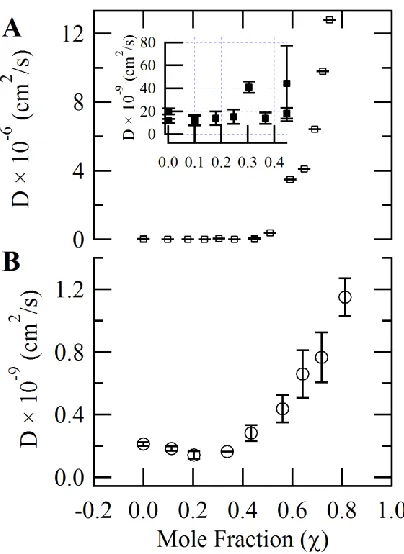
Figure 2.6: Diffusion coefficient trends in DCE/IL and water/IL mixtures ... 30
Figure 2.7: Cyclic Voltammograms at w|DCE, P4441CH3SO4 ion transfer ... 34
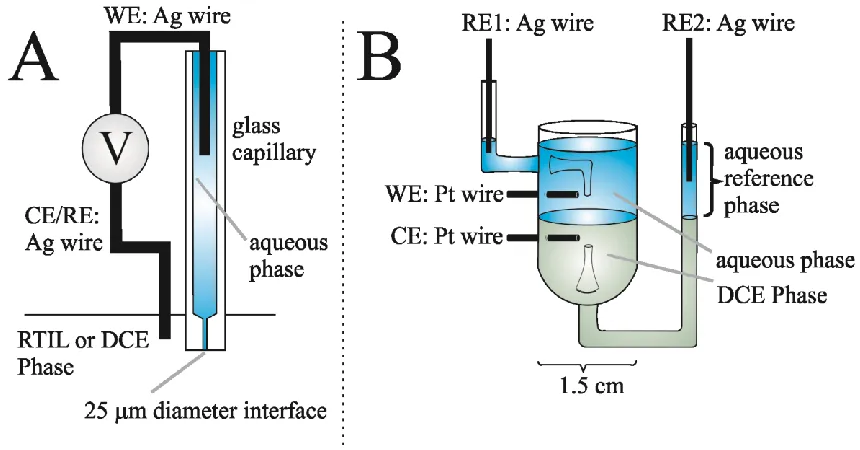
Figure 3.1: Schematic of the Experimental/Simulation Geometry. ... 44
Figure 3.2: Experimental Set-up for A: micro-ITIES; B: large-ITIES. ... 46
Figure 3.3: Simulated cyclic voltammogram of cation - anion transfers ... 47
Figure 3.4: Influence of internal diameter on the separation of cation-anion half-wave potentials ... 49
Figure 3.5: Effect of Rg on 1/2, 1 w o anion ... 50
Figure 3.6: w|IL polarizable potential windows ... 51
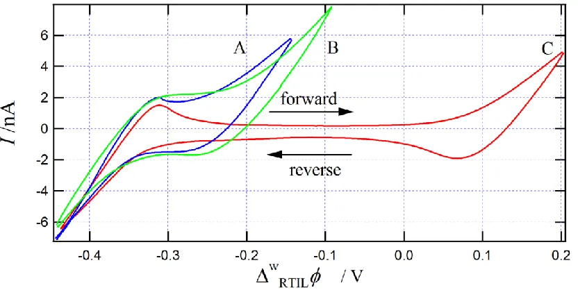
Figure 3.7: Cyclic voltammograms of P66614NTf2 IT at w|DCE micro-ITIES ... 53
Figure 3.8: Cyclic voltammograms of CMPINTf2 IT at w|DCE micro-ITIES ... 55
Figure 3.9: Cyclic voltammograms at w|DCE large-ITIES ... 57
Figure 4.1.1: Simulation geometry for (A) solid Pt disc UME; (B) liquid|liquid micro-ITIES ... 63
Figure 4.1.2: Experimental apparatus for monitoring the liquid|liquid interface ... 65
Figure 4.1.3: Preparation of P66614TB ... 66
Figure 4.1.4: CVs at a Pt disc UME immersed in P66614TB ionic liquid ... 70
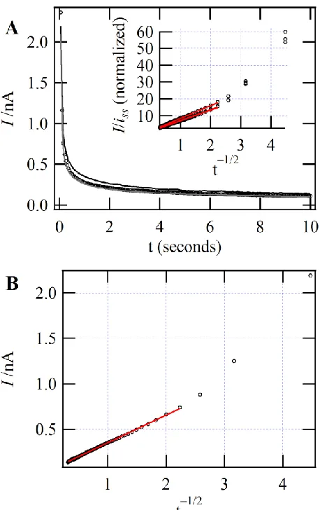
Figure 4.1.5: (A) CA curves, (B) I vs t-1/2, and (C) I/iss vs t-1/2 ... 73
Figure 4.1.6: Experimental and Simulated CVs of Fc/Fc+ redox couple as a UME ... 77
Figure 4.1.7: CV obtained at the w|P66614TB micro-ITIES ... 78
Figure 4.1.8: TPAs+ and TPB− IT at w|P66614TB micro-ITIES ... 80
xv
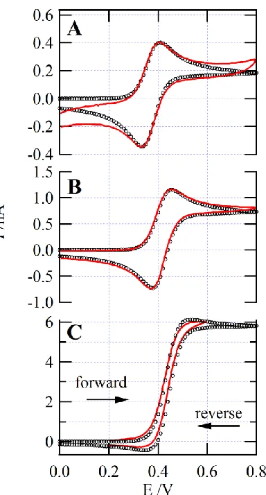
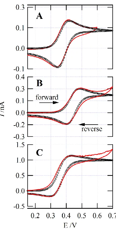
Figure 4.2.2: CVs acquired at a UME for (A) blank, (B) TCNQ, (C) DMFc, and (D) Fc
redox couples ... 95
Figure 4.2.3: CV of blank w|P8888TB micro-ITIES ... 98
Figure 4.2.4: CVs of for TATB calibration of the w|P8888TB PPW ... 100
Figure 4.2.5: CVs of alkylammonium IT at the w|P8888TB interface ... 102
Figure 4.2.6: CV of TMA+ IT with overlaid simulated curve ... 103
Figure 4.2.7: Simulated CVs looking at altering ko ... 103
Figure 5.1: CVs of alkylphosphonium IT at the w|DCE micro-interface ... 112
Figure 5.2: CVs acquired using Cell 5.2 ... 114
Figure 5.3: DPVs acquired using Cell 5.2 ... 116
Figure 5.4: DPVs acquired using Cells 5.2 and 5.3 ... 118
Figure 6.1.1: CVs and DPVs acquired using Cell 6.1.1 ... 127
Figure 6.1.2: DPVs acquired using Cell 6.1.1 and varying the supporting electrolyte concentration in either phase ... 129
Figure 6.1.3: DPVs of Cell 6.1.1 for alkali metal ions ... 131
Figure 6.1.4: DPVs of TMA+ and TB− IT ... 133
Figure 6.2.1: (A) micropipette holder and (B) component diagram ... 140
Figure 6.2.2: CV and DPV acquired for Cell 6.2.1 with X equal to Sr2+ ... 141
Figure 6.2.3: CV and DPV acquired for Cell 6.2.1 with X equal to UO22+ ... 144
Figure 6.3.1: Simulation Geometry ... 151
Figure 6.3.2: Two-electrode microhole electrolytic cell ... 153
Figure 6.3.3: LSV of Cell 6.3.1 with Wilkes IT curve fitting method ... 154
Figure 6.3.4: LSV of Cell 6.3.1 and curve fitting through 'inverse-master-equation' .. 158
Figure 6.3.5: Simulated LSVs ... 160
Figure 6.3.6: Simulated LSVs overlaid onto experimental ones ... 163
Figure 6.4.1: NP simulation geometry ... 169
Figure 6.4.2: Simulated LSVs varying the zi to zj ratio ... 171
Figure 6.4.3: Microhole electrolytic cell ... 173
xvi
Figure 6.4.6: Simulated LSVs generated using NP series of equations ... 178
Figure 6.5.1: Micropipette simulation geometry ... 186
Figure 6.5.2: CVs acquired at the w|P8888TB interface with TMA+ IT described ... 189
Figure 6.5.3: Overlaid simulated CVs ... 191
Figure 6.5.4: Working Curve ... 192
Figure 6.5.5: CVs obtained using Cell 6.4.1 with X equal to Li+, Na+, K+, Rb+, and Cs+ ... 194
Figure 7.1.1: CVs obtained using Cell 7.1.1 with varying [TBP] in the DCE phase ... 203
Figure 7.1.2: F/(RT)( ' ') z z n w o w o o iL o i z vs. ln[ * , TBP o c ] ... 207
Figure 7.1.3: Proposed structures of A: UO2NO3TBP4+ and B: UO2NO3TBP3+ ... 209
Figure 7.1.4: CVs obtained using Cell 7.1.2 with varying * , CMPO o c ... 210
Figure 7.1.5: F/(RT)( ' ') z z n w o w o o iL o i z vs. ln[ * , CMPO o c ] ... 211
Figure 7.1.6: Proposed structure ofUO2NO3CMPO3+ ... 212
Figure 7.2.1: Modified HEKA capillary holder setup ... 220
Figure 7.2.2: BESI-MS setup ... 222
Figure 7.2.3: CVs obtained using Cells 7.2.1 and 7.2.2 ... 223
Figure 7.2.4: CVs obtained using Cells 7.2.1 with varying * , CMPO o c ... 225
Figure 7.2.5: Plot of / ( )
' '
z z n w o w o i o iL o i z F RT versus
*
CMPO, ln c o ... 226Figure 7.2.6: Mass spectra acquired using BESI and ESI-MS ... 229
Figure 7.2.7: CVs obtained using Cells 7.2.2 with varying * ,IL CMPO c ... 232
Figure 7.2.8: DPV obtained using Cell 7.2.2 with * ,IL CMPO c = 111 mM... 233
Figure 7.2.9: Plot of / ( )
' '
z z n w o w o i IL iL IL i z F RT versus
*
, ln cCMPO IL ... 235Figure 7.2.10: Proposed structures of [SrCMPO2∙2H2O]2+ and [SrCMPO3]2+ ... 236
Figure 7.3.1: CVs obtained using Cells 7.3.1 with varying * , CMPO o c ... 245
xvii
Figure 7.3.5: A: Plot of / ( )
' '
z z
n
w o w o i IL iL IL i
z F RT
versus
*
,
ln cCMPO IL and (B)
proposed structure of RbCMPO4+. ... 254
Figure 7.4.1: CVs obtained using Cells 7.4.1 with varying * , CMPO o c ... 263
Figure 7.4.2: Graph of / ( )
'z z'
n w o w o o iL o i zF RT versus
*
, ln cCMPO o ... 265Figure 7.4.3: Mass spectrum of water-DCE emulsion ... 267
Figure 7.4.4: CVs obtained using Cells 7.4.2 while varying * ,IL CMPO c ... 268
Figure 7.4.5: Plot of / ( )
' '
z z n w o w o i IL iL IL i z F RT versus
*
, ln cCMPO IL ... 269List of Tables Table 3.1: Ionic Liquids ... 42
Table 3.2: Effect of Rg on 1/2 w o and iss for IT ... 51
Table 3.3: w o' o and w o tr w oG of the 8 IL components. ... 55
Table 4.1.1: Conductivity measurements obtained using complex impedance method. 71 Table 4.1.2: Electro- and Physicochemical data for (A) P66614TB and (B) P66614NTF2. 74 Table 4.1.3: Ion transfer data at the w| P66614TB micro-ITIES. ... 83
Table 4.2.1: Density, viscosity, and conductivity measurements of P8888TB. ... 98
Table 4.2.2: Formal ion transfer potentials for ions at the w|P8888TB interface. ... 102
Table 5.1: Structural list of quaternized phosphonium ionic liquids. ... 109
Table 5.2: List of IL cation formal IT potentials and estimated Ksp of the I− and B(C6F5)− salts. ... 119
Table 6.1.1: Formal IT potentials of alkali metal ions ... 132
Table 7.1.1: Uranyl-TBP complexation data ... 207
Table 7.1.2: Uranyl-CMPO complexation data ... 212
Table 7.2.1: Sr-CMPO complexation data ... 227
xviii
a activity
A ampere (unit)
ACT aqueous complexation and transfer Ae electrode area
AECL Atomic Energy Commission Ltd. amu atomic mass units
aq aqueous phase
BESI-MS Biphasic Electrospray Ionization Mass Spectroscopy
BV Butler-Volmer
CANDU Canadian Deutrium Uranium [Nuclear Reactor] CN coordination number
CT charge transfer CV cyclic voltammetry DCE 1,2-dichloroethane DCM dichloromethane DMFc decamethylferrocene
DPV differential pulse voltammetry
ESI-MS Electrospray Ionization Mass Spectroscopy ET electron transfer
F Faradays constant
Fc ferrocene
FcCH2OH ferrocene methanol
FIT facilitated ion transfer
I current
ICP-AES Inductively Coupled Plasma Atomic Emission Spectroscopy IL ionic liquid
IT ion transfer
ITIES interface between two immiscible electrolyte solustions
J total flux
Ksp solubility product constant
l distance between two parallel plate electrodes
M metal
MJ megajoules
MS Mass Spectrometry
n ligand stoichiometry
NB nitrobenzene
xix NTf2 bis(trifluoromethylsulfonyl)imide
o organic phase
Ox oxidized species
P66614TB trihexyltetradecylphosphonium tetrakis(pentafluorophenyl)borate
P8888TB tetraoctylphosphonium tetrakis(pentafluorophenyl)borate
Pa pascals
PPW polarizable potential window PUREX Plutonium URanium Extraction PZC point of zero charge
R universal gas constant Red reduced species Rs solution resistance
RTIL room temperature ionic liquid
S solution
SNF spent nuclear fuel T temperature in Kelvin
t time
TATB tetraphenylarsonium tetraphenylborate TB tetrakis(pentafluorophenyl)borate TBA tetrabutylammonium
TBP tributylphosphate
TDATPBCl tetradecylammonium tetrakis(parachlorophenyl)borate TEA tetraethylammonium
TFT trifluorotoluene
TIC transfer through interfacial complexation TID transfer through interfacial decomplexation TMA tetramethylammonium
TOC transfer and organic phase complexation TPrA tetrapropylammonium
tr transfer (superscript) TRUEX TRans-Uranium EXtraction UME ultramicroelectrode
v scan rate
w aqueous phase
x distance to the interface
zeff effective charge of a metal ion-ligand complex
xx
η viscosity
μ chemical potential
xxi
'
1/2
Galvani potential difference between phase and standard ion transfer potential
formal ion transfer potential w o w o o w o o w o w o max half-wave potential
peak potential (cyclic voltammetry)
potential at maxiumum current response (differential pulse voltammetry) pulse amplitude w o p w o E G , ' 1/2 ' ,
Gibbs free energy
Gibbs free energy from phase to
half-wave potential at a metal-solution interface formal redox potential
concentration
w o o tr o i
G w o
E E c * , , , , ' ,
of species in phase initial ligand concentration in phase
diffusion coefficient of species in phase
μ formal chemica
L i i i o i i c D i D D ,
l potential of species in phase electrode radius
hydrodynamic radius external glass radius R ratio of to ; /
d a g
g d g d g
p c
i r
r a
r a r a
i
,a
cathodic peak current anodic peak current steady state current Boltzmann's constant
rate of the forward reaction p ss f b i i k k
k rate of the reverse reaction standard rate constant charge of species
o i
k
z i
Chapter 1 – Introduction
1.0 – Energy Production for the Future
As developing nations move quickly towards industrialization and modernization, powering these emerging economies, while maintaining or improving energy production in the developed world, will be a major undertaking. Indeed, energy production will be one of the dominant global concerns facing the contemporary socio-political landscape – and scientists – moving forward into the 21st century. All of these issues need to be addressed through the lens of environmental sustainability and stewardship. The main challenge will be to remove the current dependence on fossil fuels. Fossil fuels are a finite resource that is quickly being depleted and they have also played a significant role in anthropogenic climate change. Presently, several energy harvesting technologies have emerged which meet these criteria including solar, wind, hydroelectric, and geothermal power, along with nuclear fusion and fission power [1].
Solar power is quite promising; however, it suffers from several critical drawbacks. While a great deal of progress has been made with multi-junction solar cells [2], demonstrating energy conversion efficiencies of ~40-50%, most laboratory devices elicit 10 to 20% efficiency [3-6], with commercial products falling even shorter [1]. Great strides need to be made if solar power is to become the dominant energy producer. The major hindrance to solar, wind, and hydroelectric power is intermittency; power generation is currently ‘on-demand’, that is electricity is generated as it is needed. If these energy generation technologies are to become viable options, then progress needs to be made in energy storage devices [1]. Admittedly, hydroelectric power can overcome this through the incorporation of generators into dams; however, this introduces a host of other environmental concerns like flooding of areas behind the dam.
should be noted that even nuclear fusion isn’t entirely sustainable [9]; it requires materials like lithium and deuterium – the former having uses as an energy storage material that will be integral to the electronics and automotive industries over the next few decades. So, while the amount of energy gained from nuclear fusion is theoretically impressive, it is still based on a finite resource. Nevertheless, despite the massive funding and tremendous amount of work already accomplished, nuclear fusion as a viable power source is still considered far off [1].
This means that the most successful approach to energy production, if nations are to abandon power created using fossil fuels, is nuclear fission. While providing only ~5 % of the world’s energy [1, 9], fission is a proven technology that could supplement global power. It is based on a finite resource and best estimates – considering a once through system and known uranium reserves – place a life time of 60 years for the industry [1]. The fission process, simply put, involves the 235U isotope – the highly radioactive isotope of uranium that comprises about 0.7 % of natural uranium [10]. 235U, when bombarded with neutrons, breaks down into two medium sized atoms with an average mass of 118 amu [11], while releasing energy and more neutrons.
The two atoms produced, sometimes called fission fragments, have atomic masses ranging from between zinc and erbium on the periodic table (totalling more than 40 possible elements); the distribution of atomic masses of the two atoms is actually bimodal and centered around 94Sr and 137Cs [11]. The energy released is in the form of heat and used for boiling water, which in turn spins turbines, converting the energy to electricity. The neutrons emitted sustain the fission reaction; however, the fission fragments produced often have large neutron cross-sections; that is, they absorb neutrons effectively poisoning the reaction so that fission is no longer sustainable. At this point, the fuel is removed from the reactor despite the fact it contains ~95 % useable uranium [10, 12] and referred to as SNF or nuclear waste.
fraction prepared in those early bench-top experiments. Presently, the mass of radioactive material produced through both military and commercial applications is significant [10, 18]. It is critical, however, to view SNF not as nuclear waste, but as a potential source.
The contemporary attitude of most governments toward SNF can be characterized in three ways [10, 12]:
1. Long term deep geological disposal
2. Surface disposal or containment with continuous monitoring
3. Recycling to isolate valuable isotopes and uranium fuel – a closed loop fuel cycle
Currently, no agency has been successful in fully developing and utilizing a deep geological repository [12], which means most SNF is kept in surface facilities. However, if the industry is to become sustainable, then the fuel needs to be recycled. Indeed, it has been proposed that if a so-called closed loop cycle was imposed, and combined with breeder reactors, then this could potentially increase the life span of the industry by hundreds of years [12]. The question then becomes: how can these fission fragments be removed and the greater than 95 % useable fuel be put back into the reactor?
This question was addressed early on and several processes – predominately solvent extraction techniques [12, 18] using various ligands, dissolved in a paraffinic organic solvent, to coordinate selectively to the uranium dissolved in an acidic aqueous phase – were developed. This process is shown, for example, using dioxouranium, UO22+, the common form of uranium in SNF [10], and a typical ligand tributylphosphate
[12, 18], TBP, in equation 1.1:
2
2(aq) (org) 2 3(aq) 2( 3 2) n org( )
UO nTBP NO UO NO TBP (1.1)
During the extraction, dioxouranium coordinates to two nitrate molecules (in order to maintain electroneutrality) and complexes with n TBP compounds; with n equal to 2 [19]. Two major concerns deter most programs from the reclamation of SNF: its radiotoxicity and the threat of nuclear proliferation (the production of nuclear weapons) [10, 12, 18].
fission is to become sustainable, then recycling of SNF must become more attractive. Because of the high radiotoxicity after it leaves the reactor, SNF must be handled remotely [10] so a simplified mechanical approach with minimal maintenance required is best.
1.1 – Ionic Liquids
Over the past 30 years, air and water stable ionic liquids (ILs) [20-22] have been developed and offer possible avenues for SNF recycling. ILs are defined as salts with melting points below 100ºC where the cation is typically large and organic [22-24]. These salts present a promising way of electrochemically separating SNF while simplifying the process and thus making it more cost effective and attractive [23].
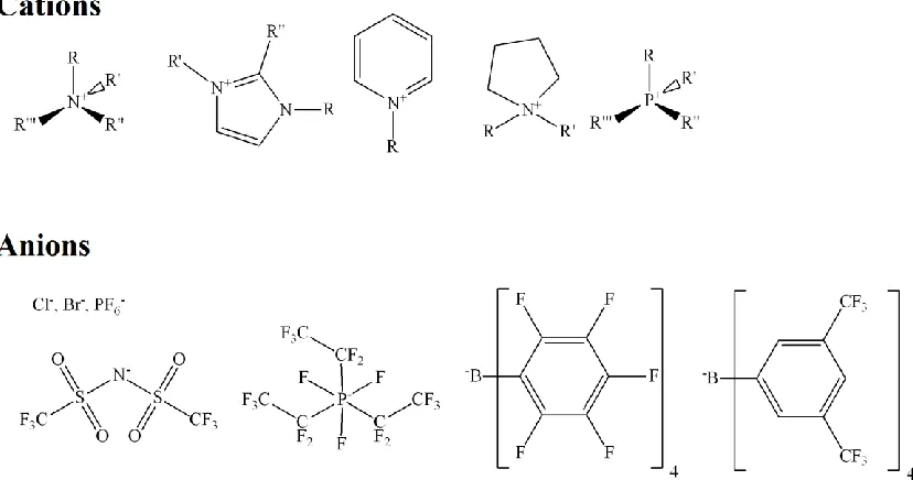
Figure 1.1 illustrates typical cation and anions that comprise ILs. Cations include quaternized ammoniums/phosphoniums to imidazoliums, etc., while anions can be inorganic, Cl−, Br−, and PF6− or more sophisticated such as
bis(trifluoromethylsulfonyl)imide (NTf2) or tetrakis(pentafluorophenyl)borate (TB).
Figure 1.1: Examples of some cation and anion components of ILs.
ILs have been used as solution phases for organic synthesis [24], while, because of their good conductivity and stability, they have also found use in a broad range of electrochemical applications [25-38]. Critically, in 1999 Dai et al. [39] demonstrated that water-IL biphasic separations had improved extraction efficiencies versus conventional water-organic solvent systems. Since that initial discovery, there has been great interest in using ILs in biphasic, water-IL, metal extractions [23, 40-48].
1.2 ‒ Liquid|Liquid Electrochemistry
Metal ion extraction, as exemplified in equation 1.1, is accomplished through mechanical separation [12, 18]; that is, the phases containing the metal ions and ligands are physically mixed using centrifugation, or by simple shaking, such that the neutral metal-nitrato-complex partitions. Because they are ions, instead of using physical means an external potential may be applied across the boundary between the two phases, water and oil (or IL), as they do not mix. This potential is referred to as the Galvani potential difference and this type of electrochemistry is often call liquid|liquid electrochemistry.
Most analytical electrochemical investigations, indeed electrochemical processes,
are the result of a potential difference between two phases or regions, ;
where and are the inner potentials within generic phases α and β. Whether this is
across a metal-solution interface, M S, or across the water-organic solvent interface,
w o
; conceptually these are equivalent to the point where most mathematical or
theoretical treatments – with regards to current responses of cyclic voltammetry (CV) or chronoamperometry (CA) – are transferable [33, 49-51].
It is commonly understood that current (I) is related to charge (Q) through the following integral [52]:
dQ
Idt (1.2)In conventional electrochemistry the electron is, in almost all cases, the charge carrier, with chemical species being oxidized or reduced as shown below using the simplest reaction for a one-electron transfer:
At liquid|liquid interfaces, the ions themselves are charge carriers and simple ion transfer (IT), for example, of species i with a charge z moving from water, w, to an organic solvent, o:
iw z i
o
z (1.4)
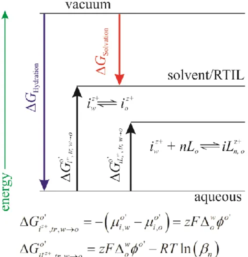
where species i is not oxidized or reduced, but simply transfers from one phase to another through a push/pull mechanism. Figure 1.2 illustrates an energy diagram taken from the perspective of a hydrophilic cation dissolved in the aqueous phase transferring from w to o; in this case, as the Galvani potential difference becomes more positive, the cation is ‘pushed’ across the interface. If the potential was then reversed, the cation would be ‘pulled’ back across the interface. Just as for the metal-solution interface where the
Gibbs free energy, G, can be related to the formal reduction/oxidation potential, Eo',
via Go' zFEo', the same is true at the liquid|liquid interface for the formal ion
transfer potential; o' w o'
tr o G zF
[33, 49].
The standard IT potential along with the Nernst equation describes the partition of
ions between phases as a function of the Galvani potential difference, , where the
activities of the ion in either phase, ai, or ai,, are known [33, 49]. However, the formal ion transfer potential describes the system when concentrations are used as an approximation of the activities; this is detailed in equation 1.5:
, , , ' ,
, , , ,
ln i ln i i ln i
o o o
i i i i
a c c
RT RT RT
zF a zF c zF c
(1.5)
Figure 1.2 also introduces another possible reaction: if a ligand, L, is dissolved in the organic, or IL, phase then partitioning of the ion becomes easier and less applied potential is required. This is referred to as ligand-assisted or facilitated ion transfer (FIT):
iwz +nL
o iLn,o
z (1.6)
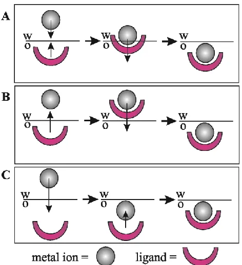
interfacial complexation (TIC) and transfer through interfacial decomplexation (TID) when reversed [53-55]. The TIC/TID mechanisms are illustrated in Figure 1.3A along with two others: aqueous complexation followed by transfer (ACT, Figure 1.3B) and transfer then organic phase complexation (TOC, Figure 1.3C).
Figure 1.2: Thermodynamic diagram of simple and facilitated ion transfer. Here the
Gibbs free energy of hydration (GHydration) and solvation (GSolvation) are shown in graphical relation. Additionally, the formal Gibbs free energy of transfer ( z', ,
o i tr w o G
)for
an ion, i, from aqueous to organic phases (w to o) is compared to the facilitated ion transfer (FIT) through complexation and the use of a ligand, L, dissolved in the organic
phase; please note that w o'
o
is the formal potential difference between the two phases, z
is the charge, R is the gas constant, T is temperature in Kelvin, β is the overall
complexation constant, and ' ,
μo
i is the formal chemical potential of species i in phase α.
Figure 1.3: Illustrations of three possible metal ion-ligand biphasic coordination mechanisms: A, transfer through interfacial complexation/decomplexation (TIC/TID); B, aqueous phase complexation and transfer (ACT); and C, transfer followed by organic phase complexation.
The investigation of liquid|liquid, or so-called soft interfaces between two immiscible electrolytic solutions (ITIES) has a rich history that began at the turn of the 20th century with early works by Nernst and Riesenfeld [50, 56]. These initial experiments were focused on measuring ion transport numbers in organic solvents and utilized a water|phenol|water system [50, 56] along with coloured electrolytes such as KI3.
By 1939 Verwey and Niessen [57] described the interface as two back-to-back double layers in analogy to the working description of the metal-solution interface with its inner and outer Helmholtz planes (IHP and OHP), or space charge regions, but with an inner, overlapping diffuse layer. Continuation in this exotic field of electrochemistry would progress through the interest of early physiologists [58, 59] who were keen to elucidate the physical and chemical nature of these interfaces as they represented simplified biomimetics for cellular membranes.
potential difference across the ITIES, the field underwent a renaissance. During the 1970’s and 80’s, aided by modern electrochemical instrumentation and techinques [50, 62-81] the four faradaic processes at liquid|liquid interfaces began to be rigorously quantified – including electron transfer (ET) [64, 66-69], simple IT [62, 64, 65, 68, 69], FIT [70, 74, 81], as well as photoinduced electrochemical reactions. With a greater understanding a more vivid thermodynamic picture was forming. Non-faradaic processes were not ignored and studies of the adsorption of material at the interface also appeared [63, 77]. The liquid|liquid double layer structure was re-examined [63, 71, 72] often using a Gouy-Chapman approach to evaluate the potential profile. As this science developed into the 90’s and 2000’s, attention switched from conventional biphasic systems like water|1,2-dichloroethane (w|DCE) [25, 54, 82-90], w|nitrobenzene (w|NB) [62, 63, 65, 67, 71, 73, 91], and w|trifluorotoluene (w|TFT) [92] to w|IL through the work of Kakiuchi et al. [93-98], Samec et al. [31, 99, 100], and Ding et al. [25, 101-103].
With this deep history and theoretical background it is possible to evaluate different ligands and biphasic w|IL systems for their possible application in the reclamation of SNF.
The study of SNF recycling is a multidisciplinary approach involving many aspects of chemistry; however, liquid|liquid electrochemistry has a great deal to offer over other analytical techniques. Electrochemistry can provide sensitive kinetic and thermodynamic information about biphasic separations that other analytical techniques, such as Inductively Coupled Plasma Atomic Emission Spectroscopy [23], have to measure indirectly. Electrochemistry can also be reduced in scale through the use of micro-ITIES such that the total size, or volume of the experiment can be reduced. This is advantageous since ILs can be expensive; therefore, reducing the volume of material needed to perform experiments is advantageous. Additionally, electrochemical experiments at liquid|liquid interfaces are easy to perform since no electrode polishing is required, as is the case for metal-solution interfaces.
1.3 – Scope of the Thesis
ultramicroelectrodes (UMEs), and the search for a suitably hydrophobic, commercially available IL for liquid|liquid investigations in Chapters 2 and 3. Theses Chapters include a rigorous analysis of water and organic solvent effects on the electrochemical response of electroactive species dissolved in the IL phase. Insight is provided as to the IL molecular organization within the vicinity of the electrode through changes in the diffusion coefficient of the electroactive species, determined through CV. Water and organic solvents are often contaminants in ILs; these are present through atmospheric transfer or are remaining after IL synthesis/preparation. It is important to know to what extent water and organic solvents can influence the kinetics and thermodynamics of electrochemical processes, and the results described in Chapter 2 indicate that the hydrophobicity of the IL plays a major role. Within Chapter 2 and 3, liquid|liquid electrochemistry was used to determine the hydrophobicity of the IL cation and anion components, quantitatively and separately. Because the individual IL components hydrophobicity could be discriminated, choices could then be made as to which cations and anions would make good, hydrophobic combinations.
Additionally, in Chapter 3 the micropipette geometry is explored using finite element analysis; these data provide invaluable insight into what micropipette dimensions or geometry provide the most predictable CV responses. That is, which geometries adhere best to conventional large (cm scale) electrochemical responses and, therefore, offer the most facile data treatment options.
used to approximate certain kinetic/thermodynamic constants for the investigation of FIT at w|IL interfaces. A major contribution of this work, however, was the preparation of two inexpensive, but effective, ILs; if w|IL biphasic separation is to become useful, then the cost of these materials must be reduced.
In Chapter 5 the liquid|liquid interface was used to investigate the hydrophobicity of the cationic component of ILs used as polymer additives; several of these cations were too hydrophobic to appear within the polarizable potential window (PPW) and this chapter examines how I probed beyond it to garner an approximation of their formal IT potentials. Probing beyond the PPW represents a novel innovation that can be used to estimate a wide variety of hydrophilic and hydrophobic formal IT potentials that were once thought inaccessible.
The formal IT potentials of metals of interest, like dioxouranium and strontium, serve as a point of reference when investigating FIT. Chapter 6 concerns the evaluation of these valuable constants using micro-ITIES at both the w|DCE and w|IL interfaces. A working curve method was used to evaluate the latter through the current-potential profile at the edge of the PPW. This method can be applied to any w|IL interface and is valuable since the formal IT potential is a constant not only unique to each ion species, but also to each biphasic solvent system; therefore, a universal method, such as that described in Chapter 6.5, is invaluable. Using these constants, FIT at w|IL interfaces could then be investigated.
according to the trend: Sr2+> Rb+> Cs+. Therefore, CMPO was concluded to be selective for Sr2+, at the w|IL interface employed. This comparison demonstrates the value of this facile technique for investigating the separation of the more than 40 elements found in SNF, but also shows that only a small number of ions, ILs, and ligands were analyzed – more work is needed.
1.5 – References
[1] M.I. Hoffert, K. Caldeira, G. Benford, D.R. Criswell, C. Green, H. Herzog, A.K. Jain, H.S. Kheshgi, K.S. Lackner, J.S. Lewis, H.D. Lightfoot, W. Manheimer, J.C. Mankins, M.E. Mauel, L.J. Perkins, M.E. Schlesinger, T. Volk, T.M.L. Wigley, Science 298 (2002) 981-7.
[2] R.R. King, D. Bhusari, D. Larrabee, X.Q. Liu, E. Rehder, K. Edmondson, H. Cotal, R.K. Jones, J.H. Ermer, C.M. Fetzer, D.C. Law, N.H. Karam, Prog. Photovolt.:Res. Appl. 20 (2012) 801-15.
[3] N. Camaioni, R. Po, J. Phys. Chem. Lett. 4 (2013) 1821-8. [4] H.S. Jung, J.-K. Lee, J. Phys. Chem. Lett. 4 (2013) 1682-93.
[5] A. Tapley, D. Vaccarello, J. Hedges, F. Jia, D.A. Love, Z. Ding, Phys. Chem. Chem. Phys. 15 (2013) 1431-6.
[6] D. Vaccarello, A. Tapley, Z. Ding, RSC Adv. 3 (2013) 3512-5. [7] E.I. Moses, Nucl. Fusion 49 (2009) 104022 (9pp).
[8] E.I. Moses, Fusion Eng. Des. 85 (2010) 983-6.
[9] A.M. Bradshaw, T. Hamacher, U. Fischer, Fusion Eng. Des. 86 (2011) 2770-3. [10] J. Bruno, R.C. Ewing, Elements 2 (2006) 343-9.
[11] G.R. Choppin, J. Rydberg, J.O. Liljenzin, Radiochemistry and Nuclear Chemistry, 2nd ed., (c) Butterworth-Heinemann Ltd. 1995, 1995.
[12] K.L. Nash, Twenty-First Century Approaches to Actinide Partitioning, in: G.J. Lumetta, K.L. Nash, S. Clark, B. , J.I. Friese (Eds), Separations for the Nuclear Fuel Cycle in the 21st Century, American Chemical Society, Washington, DC, 2006, pp. 22-40.
[13] L. Rutherford, J. Chem. Soc. (Resumed) 0 (1936) 508-16.
[14] M. Curie, Compt. Rend. Hebd. Seances Acad. Sci. 142 (1906) 273-6.
[15] A.O. Nier, E.T. Booth, J.R. Dunning, A.V. Grosse, Phys. Rev. 57 (1940) 546. [16] K.K. Darrow, Science 91 (1940) 514-6.
[17] H.G. Graetzer, Am. J. Phys. 32 (1964) 9-15.
[18] K.L. Nash, J.C. Braley, Chemistry of radioactive materials in the nuclear fuel cycle, in: K.L. Nash, G.J. Lumetta (Eds), Advanced Separation Techniques for Nuclear Fuel Reprocessing and Radioactive Waste Treatment, Woodhead Publishing Ltd., Sawston, Cambridge UK, 2011, pp. 3-22.
[19] J.H. Burns, Inorg. Chem. 20 (1981) 3868-71. [20] J.F. Knifton, J. Mol. Catal. 43 (1987) 65-77.
[21] J.S. Wilkes, M.J. Zaworotko, J. Chem. Soc., Chem. Commun. (1992) 965-7. [22] T. Welton, Chem. Rev. 99 (1999) 2071-84.
[25] B.M. Quinn, Z. Ding, R. Moulton, A.J. Bard, Langmuir 18 (2002) 1734-42.
[26] U. Schroder, J.D. Wadhawan, R.G. Compton, F. Marken, P.A.Z. Suarez, C.S. Consorti, R.F. de Souza, J. Dupont, New J. Chem. 24 (2000) 1009-15.
[27] M.C. Buzzeo, O.V. Klymenko, J.D. Wadhawan, C. Hardacre, K.R. Seddon, R.G. Compton, J. Phys. Chem. A 107 (2003) 8872-8.
[28] A.S. Barnes, E.I. Rogers, I. Streeter, L. Aldous, C. Hardacre, R.G. Compton, J. Phys. Chem. B 112 (2008) 7560-5.
[29] S.R. Belding, N.V. Rees, L. Aldous, C. Hardacre, R.G. Compton, J. Phys. Chem. C 112 (2008) 1650-7.
[30] L.E. Barrosse-Antle, A.M. Bond, R.G. Compton, A.M. O'Mahony, E.I. Rogers, D.S. Silvester, Chem. Asian J. 5 (2010) 202-30.
[31] J. Langmaier, Z. Samec, Electrochem. Commun. 9 (2007) 2633-8. [32] J. Langmaier, Z. Samec, Anal. Chem. 81 (2009) 6382-9.
[33] Z. Samec, J. Langmaier, T. Kakiuchi, Pure Appl. Chem. 81 (2009) 1473-88.
[34] J. Langmaier, Z. Samec, E. Samcová, P. Tůma, Electrochem. Commun. 24 (2012) 25-7.
[35] T. Kakiuchi, N. Tsujioka, Electrochem. Commun. 5 (2003) 253-6.
[36] C. Zhao, D.R. MacFarlane, A.M. Bond, J. Am. Chem. Soc. 131 (2009) 16195-205. [37] M. Harati, J. Jia, K. Giffard, K. Pellarin, C. Hewson, D.A. Love, W.M. Lau, Z. Ding,
Phys. Chem. Chem. Phys. 12 (2010) 15282-90.
[38] J.M. Pringle, Phys. Chem. Chem. Phys. 15 (2013) 1339-51.
[39] S. Dai, Y.H. Ju, C.E. Barnes, J. Chem. Soc., Dalton Trans. (1999) 1201-2.
[40] M.P. Jensen, J.A. Dzielawa, P. Rickert, M.L. Dietz, J. Am. Chem. Soc. 124 (2002) 10664-5.
[41] P. Giridhar, K.A. Venkatesan, T.G. Srinivasan, P.R.V. Rao, J. Radioanal. Nucl. Chem. 265 (2005) 31-8.
[42] J. Pernak, F. Stefaniak, J. Węglewski, Eur. J. Org. Chem. 2005 (2005) 650-2. [43] A. Chaumont, G. Wipff, Phys. Chem. Chem. Phys. 8 (2006) 494-502.
[44] M.L. Dietz, D.C. Stepinski, Talanta 75 (2008) 598-603.
[45] P. Giridhar, K.A. Venkatesan, S. Subramaniam, T.G. Srinivasan, P.R.V. Rao, J. Alloys Compd. 448 (2008) 104-8.
[46] A. Rout, K. Venkatesan, T. Srinivasan, P. Vasudeva Rao, J. Radioanal. Nucl. Chem. 290 (2011) 215-9.
[47] Y. Dai, J. van Spronsen, G.-J. Witkamp, R. Verpoorte, Y.H. Choi, Anal. Chim. Acta 766 (2013) 61-8.
[48] T. Vander Hoogerstraete, S. Wellens, K. Verachtert, K. Binnemans, Green Chem. 15 (2013) 919-27.
[49] S. Liu, Q. Li, Y. Shao, Chem. Soc. Rev. 40 (2011) 2236-53.
[50] H.H.J. Girault, D.J. Schiffrin, Electrochemistry of Liquid-Liquid Interfaces, in: A.J. Bard (Ed) Electroanalytical Chemistry, Marcel Dekker, New York, 1989, pp. 1-141.
[51] H. Girault, Electrochemistry at Liquid-Liquid Interfaces, in: A.J. Bard, C.G. Zoski (Eds), Electroanalytical Chemistry, CRC Press, 2010, pp. 1-104.
[52] A.J. Bard, L.R. Faulkner, Electrochemical Methods: Fundamentals and Applications, 2nd ed., John Wiley, New York, 2001.
[54] F. Reymond, G. Lagger, P.-A. Carrupt, H.H. Girault, J. Electroanal. Chem. 451 (1998) 59-76.
[55] P.D. Beattie, R.G. Wellington, H.H. Girault, J. Electroanal. Chem. 396 (1995) 317-23.
[56] W. Nernst, E.H. Riesenfeld, Ann. der Physik 8 (1902) 600-8.
[57] E.J.W. Verwey, K.F. Niessen, Philos. Mag. (1798-1977) 28 (1939) 435-46. [58] J.T. Davies, S.E. Rideal, Can. J. Chem. 33 (1955) 947-60.
[59] J.T. Davies, J.B. Wiggill, Proc. R. Soc. London, Ser. A 255 (1960) 277-91.
[60] C. Gavach, T. Mlodnicka, J. Guastalla, C. R. Acad. Sci., Paris, Ser. C 266 (1968) 1196-9.
[61] C. Gavach, F. Henry, C. R. Acad. Sci., Ser. C 274 (1972) 1545-8.
[62] C. Gavach, F. Henry, J. Electroanal. Chem. Interfacial Electrochem. 54 (1974) 361-70.
[63] C. Gavach, P. Seta, B. D'Epenoux, J. Electroanal. Chem. 83 (1977) 225-35. [64] Z. Samec, J. Electroanal. Chem. Interfacial Electrochem. 99 (1979) 197-205.
[65] Z. Samec, V. Mareček, J. Weber, J. Electroanal. Chem. Interfacial Electrochem. 100 (1979) 841-52.
[66] Z. Samec, J. Electroanal. Chem. Interfacial Electrochem. 103 (1979) 1-9.
[67] Z. Samec, V. Mareček, J. Weber, J. Electroanal. Chem. Interfacial Electrochem. 103 (1979) 11-8.
[68] Z. Samec, J. Electroanal. Chem. Interfacial Electrochem. 111 (1980) 211-6.
[69] Z. Samec, V. Mareček, J. Weber, D. Homolka, J. Electroanal. Chem. Interfacial Electrochem. 126 (1981) 105-19.
[70] Z. Samec, D. Homolka, V. Mareček, J. Electroanal. Chem. Interfacial Electrochem. 135 (1982) 265-83.
[71] Z. Samec, V. Mareček, D. Homolka, Faraday Discussions of the Chemical Society (1984) 197-208.
[72] Z. Samec, Chem. Rev. 88 (1988) 617-32.
[73] J. Koryta, P. Vanýsek, M. Březina, J. Electroanal. Chem. Interfacial Electrochem. 75 (1977) 211-28.
[74] D. Homolka, L.Q. Hung, A. Hofmanova, M.W. Khalil, J. Koryta, V. Mareček, Z. Samec, S.K. Sen, P. Vanysek, Anal. Chem. 52 (1980) 1606-10.
[75] J. Koryta, Electrochim. Acta 29 (1984) 445-52.
[76] H.H.J. Girault, D.J. Schiffrin, J. Electroanal. Chem. 161 (1984) 415-7. [77] H.H.J. Girault, D.J. Schiffrin, J. Electroanal. Chem. 179 (1984) 277-84. [78] H.H.J. Girault, D.J. Schiffrin, J. Electroanal. Chem. 195 (1985) 213-27. [79] H.H.J. Girault, D.J. Schiffrin, Electrochim. Acta 31 (1986) 1341-2. [80] H.H.J. Girault, D.J. Schiffrin, J. Electroanal. Chem. 244 (1988) 15-26. [81] J. Koryta, Electrochim. Acta 24 (1979) 293-300.
[82] Z. Ding, D.J. Fermin, P.-F. Brevet, H.H. Girault, J. Electroanal. Chem. 458 (1998) 139-48.
[83] F. Reymond, P.-A. Carrupt, H.H. Girault, J. Electroanal. Chem. 449 (1998) 49-65. [84] T.J. Stockmann, Z. Ding, J. Electroanal. Chem. 649 (2010) 23-31.
[85] N.R. Partovi, B. Su, M.A. Mendez, J.-M. Barbe, Z. Samec, H.H. Girault, J. Electroanal. Chem. 656 (2011) 147-51.
[87] T.J. Stockmann, Z. Ding, Anal. Chem. 83 (2011) 7542-9.
[88] P. Sun, F.O. Laforge, M.V. Mirkin, J. Am. Chem. Soc. 129 (2007) 12410-+. [89] P. Sun, F.O. Laforge, M.V. Mirkin, J. Am. Chem. Soc. 127 (2005) 8596-7.
[90] Y. Wang, J. Velmurugan, M.V. Mirkin, P.J. Rodgers, J. Kim, S. Amemiya, Anal. Chem. 82 (2010) 77-83.
[91] Y. Yuan, Z. Gao, M.Q. Zhang, Z.Q. Zhang, Y.H. Shao, Sci. China, Ser. B 45 (2002) 494-502.
[92] A.J. Olaya, P. Ge, H.H. Girault, Electrochem. Commun. 19 (2012) 101-4.
[93] T. Kakiuchi, N. Tsujioka, S. Kurita, Y. Iwami, Electrochem. Commun. 5 (2003) 159-64.
[94] N. Nishi, S. Imakura, T. Kakiuchi, Anal. Chem. 78 (2006) 2726-31.
[95] N. Nishi, T. Kawakami, F. Shigematsu, M. Yamamoto, T. Kakiuchi, Green Chem. 8 (2006) 349-55.
[96] N. Nishi, H. Murakami, S. Imakura, T. Kakiuchi, Anal. Chem. 78 (2006) 5805-12. [97] N. Nishi, A. Suzuki, T. Kakiuchi, Bull. Chem. Soc. Jpn. 82 (2009) 86-92.
[98] Y. Yasui, Y. Kitazumi, R. Ishimatsu, N. Nishi, T. Kakiuchi, J. Phys. Chem. B 113 (2009) 3273-6.
[99] J. Langmaier, A. Trojanek, Z. Samec, Electroanalysis 21 (2009) 1977-83.
[100] J. Langmaier, S. Záliš, Z. Samec, V. Bovtun, M. Kempa, Electrochim. Acta 87 (2013) 591-8.
[101] T.J. Stockmann, Y. Lu, J. Zhang, H.H. Girault, Z. Ding, Chem. Eur. J. 17 (2011) 13206-16.
Chapter 2 - Electrochemical behavior of tributylmethylphosphonium methyl sulfate mixtures with water and 1,2-dichloroethane
2.1 ‒ Introduction
Ionic liquids (ILs) have undergone extensive research over the past 20 to 30 years since Wilkes et al. [1] and Knifton [2] prepared some of the first, modern air- and water-stable versions. ILs are described as large organic salts with melting points typically below 100ºC. These unique solvents have been utilized successfully in inorganic [3] and organic [4, 5] synthesis, in solar cell applications [6], in polymer films [7], and in biphasic metal ion extraction [8, 9]. With trillions of ILs speculated to be possible [5, 10] ‒ through variation of cation and anion structure or pairing different ion combinations together ‒ it is not surprising ILs have permeated so many materials and chemical applications since their physicochemical properties are just as varied. One needs to simply select the IL with the desired properties; the only limitation being the amount of comprehensive, physicochemical IL data available in the literature [5, 10-12].
Several common features are pervasive in ILs, including a high thermal stability, low vapour pressure, and good electrochemical stability [3, 5, 13]. This last property translates to wide electrochemical potential windows [13], that is the potential at a working electrode can be swept in electrochemistry from ±2 V to even ±3 V; the IL must be de-aerated, or the experiment run under an inert atmosphere, as both water and oxygen typically limit the potential window [14, 15], ILs have been shown to influence the voltammetric response of electroactive species dissolved in them [13, 16, 17] and that the diffusion coefficients of the reduced and oxidized form of a particular redox species may vary dramatically.
interface [19], suggest the IL has multilayer organization/order associated with the boundary [18, 19]. This is supported by molecular dynamic simulations, performed by other groups [20-22], whose reports predict a nano-structure at interfaces but also present evidence of organization even within the bulk phase [22].
Herein, the physicochemical properties of a phosphonium IL, tetrabutylmethylphosphonium methyl sulfate (P4441CH3SO4), while increasing organic
solvent and water content are investigated electrochemically using a chronoamperometric (CA) method developed by Aoki and Osteryoung [23, 24] and two redox probes ferrocene (Fc) and ferrocenemethanol (FcCH2OH). The measured diffusion coefficients of the
redox probes are compared to gain insight into changing IL environment with increasing molecular solvent content; these changes are contrasted against a possible nano-structure present at the w|IL interface. The hydrophobicity of P4441CH3SO4 was quantified using
liquid|liquid electrochemistry at a micro interface between two immiscible electrolytic
solutions (ITIES) housed at the tip of a 25 m diameter micropipette as was shown recently [25].
2.2 ‒ Simulation
Numerical simulations have been used successfully to describe a myriad of unique environments including electrochemistry within supercritical CO2 [26], in SECM
corrosion modelling studies [27], at liquid|liquid interfaces [28], as well as describing the fundamental responses from microelectrode arrays [29]. Herein, they are used to garner insight into the kinetics of simple one-electron reduction reactions at a ultramicroelectrode (UME).
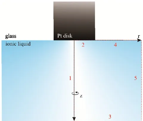
The UME geometry (Figure 2.1) was composed of 5 boundaries enclosing a domain within which mass transfer was described by Fick’s laws of diffusion through equation 2.1:
2 2
, , , ,
, 2 2
, ,
( , , ) ( , , ) 1 ( , , ) ( , , )
( , , ) 0
i i i i
i
i i
c r z t c r z t c r z t c r z t D
t r r r z
D c r z t
where ci, and Di, are the concentration and diffusion coefficient of redox species i in phase α; , or del, is the gradient or vector operator – shown here in cylindrical coordinates.
Figure 2.1: Cross-section of the ultramicroelectrode simulation geometry. The red dashed box describes the simplified simulation domain with boundaries 1, 2, 3, 4, and 5 defined as axial symmetry, the electrode surface, concentration, glass insulator, and concentration respectively
The simple one electron oxidation/reduction reaction, as defined by equation 2.2, and operated at the UME surface via boundary 2:
Ox+e- kf
kb Red (2.2)
where the oxidized species, Ox, is reduced to Red through addition of one electron, e−. The reaction kinetics is assumed to follow Butler-Volmer regime represented by equations 2.3 and 2.4 for the forward (kf) and reverse (kb) rates:
'
exp
o o
f
k k f E E (2.3)
'
exp (1 )
o o
b
k k f E E (2.4)
Here ko is the standard rate constant, α is the transfer coefficient (this was assumed to be 0.5 unless otherwise stated), and f = F/(RT); F is Faraday’s constant, R is the universal gas constant, and T is temperature in Kelvin (assumed to be room temperature, 298.15 or