Available online:
https://edupediapublications.org/journals/index.php/IJR/
P a g e | 1286IOT Based Virtual Banking
M. Varasundar & A. Praveen kumar
M.Tech Asst Professor Kasireddy Narayanreddy College of Engineering and Research. M.Tech(Embedded systems) Kasireddy Narayanreddy College of Engineerig and Research
Email:[email protected]; Email:[email protected]
Abstract
Main aim of this project is designing and
developing biometric based money payment and
transaction system. As part of digital India
transaction of liquid cash decreased usage of
digital transactions are getting increased
rapidly. Banks are using more technologies to
do secure transactions. Using finger print based
payment is more easy and secure.
Keywords: LCD (Liquid crystal display), GSM (Global system for mobile
communication), RPS (Regulated power
supply), LED (Light emitting diodes), Finger
print module, Wi-Fi (Wireless Fidelity).
I. INTRODUCTION
Now a day’s ATM’s plays major role in our
society. But sometimes we are facing lot of
problems due to ATMs. If we lost the virtual
cards there is a chance of misusing our ATMs by
someone. Even if we forgot the password we
cannot do transactions. To avoid these
drawbacks here we are
introducing a new technology that is “IOT BASED VIRTUAL BANKING”. By using this
technology we can withdraw, transfer and we
can do payments without any virtual cards like
credit cards and debit cards etc. No need to carry
virtual cards along with us. Fingerprint sensor
that can capture the finger print information
efficiently. It is used in this project to improve
the security and easy to access banking. Along
with finger print we can use password also it
will more secure than other systems. In this
system user need to keep finger on finger print
sensor if finger print is valid it will ask password
to verification itself each user has own
password. If password is matched we have to
enter amount to be transfer to other account.
On board system consist of GPIO pins the
onboard system commonly called micro
controller. The GPIO pins are connects to
different modules depending on our requirement.
Available online:
https://edupediapublications.org/journals/index.php/IJR/
P a g e | 1287It requires 5v dc supply.230v AC supply
is converts into first stepped down to 12 volts
AC by using stepped down transformer.12 v AC
is converted into dc by using rectifier. Rectifier
converts ac to pulsating dc. The pulsating dc
voltage is passed through capacitive filter to
removes
Ripples. Regulated power supply is used to
provide constant 5vto circuit. Capacitive filter is
used to convert pulsating dc to pure dc voltage.
Micro controller takes input from finger print
sensor and checks for authentication. If finger
print is valid will ask password to verification
itself each user has own password. If password
is matched we have to enter amount how much
to be transfer to others account. User registered
mobile number gets message how much money
transferred to particular account. GSM module is
used to user get message.
On board system consist of GPIO pins the
onboard system commonly called micro
controller. The GPIO pins are connects to
different modules depending on our requirement.
Available online:
https://edupediapublications.org/journals/index.php/IJR/
P a g e | 12881) HARDWARE DESCRIPTION
A) Finger print module: The ARA-EM01 is fingerprint module. It is a easy restructure,
powerful functions, compatible with PC and
multiple-functions with single module
Fingerprint enrollment, image process,
characters acquisition, fingerprint template
creation, fingerprint template storage, fingerprint
compare (1: 1, 1: N), fingerprint delete. This
module can work with UART.
B) GSM module: GSM stands for Global System for Mobile communications, in any country for
mobile communication use frequency range
between 890Mhz to 915Mhz. Hence it is called
Global System for Mobile Communication.
Main elements in GSM is MS(mobile station),
BTS(Base transiver system), BSC( Base station
controller), MSC(mobile switching center),
PSTN(public switched telephone network),
HLR(home location register), and VLR(visitor
location Register).
C) Keypad: 4X4 matrix keypad has total 16 keys arranged as 4 columns and 4 rows. 4cloums
default value is 1 and 4 rows default value is 0
by pressing switch one of the column is 0
depends on the respective row, each row
representing a low frequency, each column
representing a high frequency. If we press single
key then it will send sinusoidal signal for each of
the frequencies. Every column connected to all
rows through switch, the tones generated when
the switch pressed that is decoded by the DTMF.
D) LCD display: The LCD has 3 control lines as well as 8 data lines some applications use only 4
data lines. We need to select operate with 4 data
lines or 8 data lines. The three control lines are
EN, RS, and RW. If a 4-bit data bus is used the LCD will require a total of 7 lines controller pins
always 3 (3 control lines plus the 4 lines for the
data bus). For 8-
Bit data total of 11 data lines (3 control lines
plus the 8 lines for the data bus).The EN line is called "Enable." To send data to the LCD we
need apply logic low to EN pin. EN pin is active
low pin. RS pin is active high, RS stands for
“Register Select” which is used to know sent
data is data or command, if rs=0 then data on
data pins is commands or special instructions, if
rs=1 then data present on the data pins is treated
as data only. Commands are use to clear screen,
and set the char print location on screen.
E) Reset: Reset button is used to reset total system operation. When reset button is pressed
registers stores with default values.
F) Wi-Fi: ESP8266 is a Wi-Fi networking solution, allowing it to either host the application
or to offload all Wi-Fi networking functions
from another application processor. It has
integrated cache to improve the performance of
Available online:
https://edupediapublications.org/journals/index.php/IJR/
P a g e | 1289the memory requirements. Wi-Fi is working
through network layer of OSI 7 layers.
2) SOFTWARE DESCRIPTION
A) PIC Compiler: PIC compiler is software used where the machine language code is written and
compiled. After compilation, the machine source
code is converted into hex code which is to be
dumped into the microcontroller for further
processing. PIC compiler also supports C
language code.
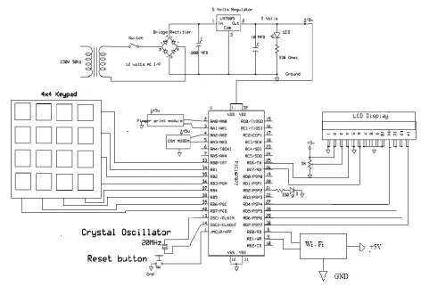
IV.METHOD
The below figure shows the schematic
diagram of IOT based virtual banking here we
are using different modules they are LCD, GSM,
Keypad, Wi-Fi, Finger print module and LED,
DC motor, Crystal oscillator. Here 230v AC
converts into 5V DC by using transformer and
maintained constant 5V by RPS.DC 5V given to
micro controller 11 And 32 pins, shown in
figure. Finger print module is connected to port
a of micro controller .port A pins are analog
input pins. Pin 2 connected to Transmitter pin of
finger print module. Micro controller verifies the
authentication if valid then it will ask password.
Pin no 33 to 40 (Port B) pin of micro controller
Available online:
https://edupediapublications.org/journals/index.php/IJR/
P a g e | 1290password is matched we have to enter amount to
be transfer. LCD is connected to c6, c7 and
D4-D7 (data) Pins of micro controller here LCD is
used to display the messages which is given by
micro controller. If transaction is completed
successfully user gets message to registered
mobile number Through GSM. GSM module is
connected to pin no 4 & 5 of micro controller.
User transaction details are stored in banking
server through Wi-Fi .Wi-Fi is connected to pin
number 8 & 9 of controller.
V.APPLICATIONS
1. Shopping malls.
2. Bus/Train ticketing system.
3. Fee payments at various educational
institutions.
4. Any other payments (alternative to cash
payment)
VI. CONCLUSION
Our paper “IOT BASED VIRTUAL
BANKING “is mainly intended to banking
applications like payments and transfer of
money with more secure without any virtual
cards.
VII. FUTURE SCOPE
We can extend as ATM machines
without using any virtual cards money
withdrawal and transfer and also add feature eye
retina scanning for more secure.
REFERENCES
[1]. Micro controller architecture, programming,
interfacing,and system design-By Raj
Kamal-2009.
[2]. PIC Microcontroller and Embedded
systems-By Mazidi Muhammad Ali
Mazidi, Rolin D. McKinley, Danny
Causey-2008.
[3]. Printed circuit Board –Design, Fabrication ,
assembly and testing-By R. S. Khandpur-2005
[4]. PIC Micro controller manual - Microchip.
[5]. PIC Microcontroller: An Introduction to
Software and Hardware Interfacing-By
Han-Way Huang-2005
[6]. Embedded C – By Michael.J.Pont – 1st
edition-2002.
[7]. Getting started with the Internet of
Things-Connecting Sensors and Microcontrollers to the
Cloud-By Cuno pfister-24 May 2011
[8]. Internet of Things: A Hands-On
Approach-By Arsheep Bahga and Vijay Madisetti-9th
Available online:
https://edupediapublications.org/journals/index.php/IJR/
P a g e | 1291[9]. Microcontroller Based DC Motors-By
Lakshminarayana Gadupudi and Heena
Chandwani-3rd September 2012.
[10]. PIC Micro controller projects in c-By
Dorgan Ibrahim-Second Edition-16 April 2014.
[11]. Internet of Things with ESP8266-By
Marco Schwartz-29 july 2016.
Author:
M. Varasundar
M.Tech Asst Professor Kasireddy Narayanreddy College of Engineering and Research.
Email:[email protected]
A. Praveen kumar
M.Tech(Embedded systems)Kasireddy Narayanreddy College of Engineerig and Research