Digital signal processing: IIR Digital Filter
Design Research and Simulation on MATLAB
Deepak kataria;
Naveen Panwar & Pankaj Kumar
Dronacharya College of engineering, Gurgaon, India
Email: [email protected]
Abstract:
In modern communication systems, filtering is the most common and extremely important signal processing technology, it is an effective method of interference suppression, and the design of filter has become the core issues of the signal processing. Generally speaking, filter can be divided into analog filter and digital filter. Today, the development of analog filter has been more mature. However, digital filter has many advantages, such as higher stability, higher precision. With the development of digital technology, using digital technology to realize filter function is widely used. Then this paper analyzes the design principle of digital filter, and introduced the impulse invariance method and window function method. This paper presents a new design of a effective IIR filter, which realized via two methods.
MATLAB is a popular numerical analysis software, providing a wealth of design tool. A MATLAB-based digital filter design procedure designs the filter, and mainly analyzes the 5-order IIR filter, which is designed using Simulink. Through the MATLAB visualization procedures given the frequency characteristic curve, comparing the simulation results. It has the high practical value.
Keywords:
Digital filters, infinite-impulseresponse (IIR) filter, impulse invariance method.
1. Introduction:
Filter, is a circuit that allows a particular frequency band through, and attenuation of signal which outside the band. Filter is used extensively, involving tele-communications, military, medical, electricity, etc. In the modern communication system, filter is one kind of signal processing technology which is used very commonly, and digital filters is better than analog filters in many ways, So, with digital technology to achieve filter function been widely used. In digital signal processing, filtering occupies an extremely important role. The input sequences of digital filter are through certain operations transform into output sequence. Digital filter core thought is prominent and effective wave, restrain the interference wave. Compared with simulation filtering, digital filtering has many outstanding qualities, such as: it can satisfy the strict requirement on amplitude and phase characteristic, overcome voltage drift, temperature drift and noise etc.
2. Digital Filter:
2.1 . The realization of digital filter:
There are two realization ways to realize Digital filter: one is the frequency domain method, using FFT
fast algorithm of the input signal to the discrete Fourier transform, and analyzes its spectrum, and then based on the expected frequency characteristics of filter, finally reuse Fourier inverse transform time signal recovers. Another method is the time domain method; this method is based on discrete sampling data for difference numerical computation to achieve filtering purpose.
2.2 The design of digital filter:
According to temporal characteristics of impulse response function, Digital filter can be divided into two kinds of, an infinite impulse response (IIR) filter and finite impulse response (FIR) filter. By digital signal processing, IIR filter’s characteristic is infinite duration of impulse response, while FIR filter is limited, lasting only a certain amount of time. The design method of digital filter is varied, like impulse invariance method and bilinear transform method, window function method and frequency sampling method.
General design procedure is as follows:
a) According to actual needs, to determine the
filter performance requirements;
b) Using a causal, stable discrete linear system
to approached this constant index;
c) Through the operation to realize the filtering
system designed;
d) Through the simulation system meets the
given technical requirements.
IIR filter is the Impulse Response with unlimited duration, this kind of Filter generally need to realize using a recursive structure, and called a recursive filter. Impulse response reform is a method for converting simulation filter to digital filter.
3. IIR Digital Filter:
IIR digital filter is unlimited duration of impulse response, this kind of filter generally need to realize using a recursive structure, and called a recursive filter. IIR filters filter expression can be defined as a difference equation: Equation (1) and (2) below:
Where x(n) and y(n) are input and output signal
sequences; and ak , bk are filter coefficients. The system transfer function can be expressed by the following equation:
N is IIR filter’s order number (or filter system transfer function’s poles count), M for filter system transfer function’s zero count, where ak and bk are weight function coefficients.
Usually, the design of IIR digital filter is via
to digital filter. The design of simulated filter is mature, therefore, make full use of the existing resources will brings many advantages for the design of digital filter.
3.1 Impulse invariance method:
impulse response h[k] by sampling interval of analog filter unit impulse response h(t), that is:
So, impulse invariance method can be finished by formula (8):
Owing to Ω = T
ω
, it is linear relationship between Simulation frequency and digital frequency.3.2 Characteristics of impulse
invariance method:
The characteristics of impulse invariance method can be conclude and given by
a) Using impulse invariance method to realize analog to digital filter, frequency conversion meet linear phase.
b) Existing aliasing phenomenon, so can't design high-pass and band-stop filters.
3.3 Design of IIR digital filter:
Using impulse invariance method to design a digital low-pass filter, design requirement: fp=2000rad/s,
Ap<3dB, fs=3000rad/s, As>15dB, Sampling frequency: Fs=10000H 。Assume a signal
x(t)=sin(2*Pi*f1*t)+0.5cos(2*Pi*f2*t) ,and
f1=1000Hz,f2=5000Hz。
From the amplitude-frequency characteristic curve, in 2000Hz place attenuation is less than 3dB and in more than 3000Hz place attenuation
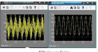
is more than 15dB, so it can satisfy the attenuation of the filter design indexes. Input function x (t) through this filter, the rendering is as shown in below fig.
It can be seen from Fig. 2, using function filtfilt (zero phase filter) for the input signal x (t), after filtering the output signal y (t) (solid line) is consistent in the phase with the input signal 1000Hz signal, that is to say, it does not change with the phase, which is the advantage of using the function; while using function filter, the
output y1 (t) (dotted line), have certain of delay compared with the original signal.
3.4 Simulink:
According to the design of filter index, FDATool interface parameters can be set as follow.
Parameters Setting
Filter Type Lowpass
Fs Fs=10000Hz
Ap,As Ap=3dB, As=15dB
Fp,Fstop Fp=2000Hz,
By calling the Simulink modules, digital filter simulation diagram is formed:
It can seen from the signal filtering rendering Fig. , the 5000Hz signal is excepted from input signal x(t).
From the above figures. , the amplitude-frequency phase amplitude-frequency characteristics and filtering effect is consistent by program design and Simulink, the effect is ideal, and meets the design requirements.
4. Conclusion:
It can design the filter quickly and effectively by MATLAB, characteristics of filters can be compared to achieve the optimum design. The higher filter order number, the better filtering effect, but the more computation time occupied, so in meet index requirements of the situation should try to reduce filter order number N. IIR digital filter can use lower order number to meet the same design requirements compare with FIR digital filter. Design filter on MATLAB is used in digital signal processing, and has wide application and development prospect.
5. Reference:
[1] Fesquet, L. IIR Digital Filtering of Non-uniformly Sampled Signals via State Representation. Signal Processing.
[2] HUANG Meng, TANG Lin, ZHEN Yu & ZHANG Jie. (2010). Optimized FIR Filter Design Based on Selfadaptive Genetic Algorithm. Modern Electronics Technique, 02. [3] Jong-Sik Lim. Design of Low-Pass Filters Using Defected Ground Structure. IEEE Transactions on Microwave
Theory & Techniques; Aug2005.
[4] WANG Yang &ZENG Yi-cheng. (2011). A complexity reduction approach for FIR notch filter design.
[5] M. D. Lutovac, D. V. Tosic, and B. L. Evans, Filter Design for Signal Processing, :Prentice-Hall R. Nicole, “Title of paper with only first word capitalized,” J. Name Stand. Abbrev., in press.
[6] A. Krukowski and I. Kale, DSP System Design: Complexity Reduced IIR Filter Implementation for Practical
Applications, Kluwer, Norwell, MA, 2003. [7] B. Farhang-Boroujeny, “A square-root Nyquist (M) filter design for digital communication systems,” IEEE Trans. Signal Process.
[8] N. Wong and C. U. Lei, "IIR approximation of FIR filters via discrete-time vector fitting," IEEE Trans. Signal