Power Saving Strategies In Wireless Sensor
Networks Using Cross Layer Design
Pranali D. Tembhurne (Nandeshwar)1, R.K. Krishna2, Nilkamal G. Ramteke3 1
Department of Computer Science & Engg.,
Nagpur Institute Of Technology, Katol Road, Mahurzari, Nagpur.
2
Department of Electronics and Tele-communication,
Rajiv Gandhi College Of Engg., Research & Technology, Chandrapur.
3
Department of Computer Engineering, SRPCE, Umred Road, Nagpur.
Abstract- The latest advances in distributed computing have enabled in the past few years the emergence of a variety of wireless sensor network applications comprising building, health, environment, industry, and military domains. Wireless sensor networks are characterized by constrained power, memory, and computational resources and require a novel design approach. The goal of this thesis is to improve energy performance by employing cross layer design. The goal is achieved by protocol architecture which supports cross layer design and routing protocols which use cross layer information. Energy performance can be enhanced by designing energy aware hardware and software. Energy aware software approach includes development of energy efficient communication protocols and getting benefits from cross layer interaction among layers. In this first, we implement the base station & mobile station. Second, we implement the modulation techniques (OFDM, BPSK, QAM, QPSK) with cyclic prefix values. And lastly, implement the cross layer design. Also we are showing the comparisons using cross layer design & without cross layer design. Simulation result shows the throughput and delay using modulation techniques and cross layer design.
Index Terms—Cross-Layer Design, Wireless Sensor Networks, Distributed Source Coding, Energy efficiency, network lifetime, Data gathering, Communication Protocol, Open System Interconnection (OSI) Model.
1. INTRODUCTION
Recent work in wireless sensor networks (WSNs) has led to increasing utilization across a broad range of markets. Sensor networks, generally speaking, are systems comprised of a multitude of spatially-distributed nodes. Each node is generally capable of sensing some environmental parameter and communicating the data back to a central location. Some developing applications include military battlefield intelligence, biomedical patient monitoring, and smart buildings. A
simple example of a ubiquitous sensor network is the security system found in many buildings today.
The functionality of a WSN node is generally implemented through electronics for sensing, intelligence (microcontroller), communication (radio) and a limited power source (battery). The communication system, utilized to transmit information between the nodes, is a major functional block in every WSN. Practical communication system design is aided by a well-defined conceptual framework called the Open System Interconnection (OSI) reference model. The OSI model is a seven-layer architecture, where each layer is responsible for specific sub-systems. The inter-layer interactions are strict,
minimal, and well-defined. Recent research has shown that the OSI model is not necessarily the correct approach for some modalities of wireless systems. Researchers have made modifications to communication protocols which violate the OSI model, but achieve specific optimization goals. These modifications are termed “cross layer design (CLD)” .
Wireless communications design is diverging from the OSI model, but there is still no standard framework for CLD. The lack of a standard framework can lead to many problems. This leads to reduced overall network performance. There are also fundamental, unanswered questions for CLD. Generally speaking, it is not clear when, where, and how different CLD proposals should be implemented. This paper is organized as follows. Section II describes the introduction of wireless sensor networks & wireless sensor nodes. Section III describes the OSI model. It identifies shortcomings of the OSI model for wireless communication systems, defines the need cross-layer design, and provides an example of how cross-layer design can improve wireless system performance and energy consumption. Section IV describes the network services. Section V shows the simulation result. In section VI, comparison is given. And in section VII, conclusion and future work is given.
2. WIRELESS SENSOR NETWORKS
Wireless sensor network is a network of spatially distributed sensor nodes equipped with sensing, computing, power, and communication modules to monitor a certain phenomenon such as environmental data or object tracking. In current scenarios, the number of sensor nodes are 6, but in future it may consist of nth power more sensor and actuator systems. The positions of the sensor nodes may not be pre-determined and may require sensor nodes to be equipped with self organizing protocols. Generally, sensor nodes observe and sense the phenomenon with a sensing module, process the data with a computing module, and send the data to a required destination over a radio interface with a communication module.
Illustrative sensor network architecture is shown in Figure 1, in which sensor nodes are distributed over a particular area of interest to collect data, process them, and send them to a sink node for further processing.
3. CASE FOR CROSS LAYER DESIGN
It is argued that layered architectures are well suited for wired communication but they do not perform well in wireless networks. In the following sections, an overview of traditional layered architectures is presented and argued why they are not suited for wireless communication networks.
3.1 Layered Approach
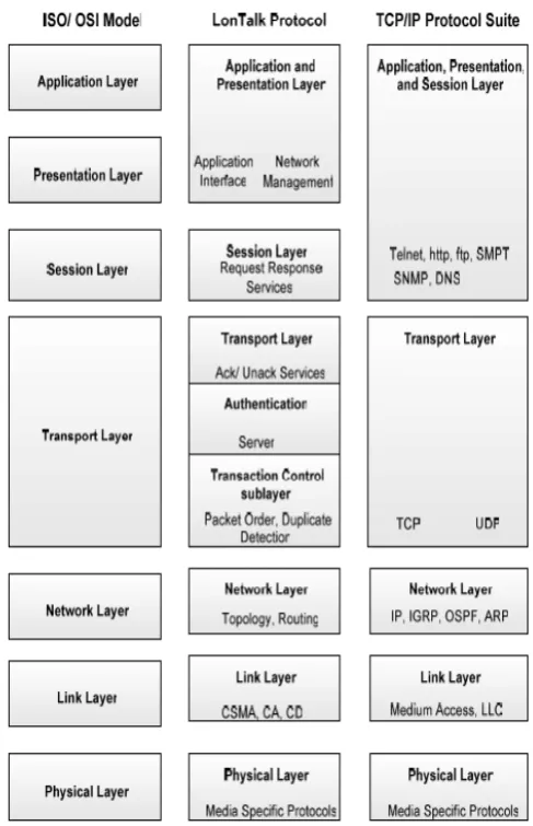
The Open Systems Interconnection (OSI) reference model divides the network architecture into seven well defined logical layers, each layer responsible for some specific task. The real world implementation of the layered approach including TCP/IP (Transmission Control Protocol/Internet Protocol) protocol suite1 and LonTalk protocol show the importance of layered architectures. The corresponding architectures are shown in Figure 2. Layer-wise functionalities discussed in and the needs to divert from traditional architectures are described as follows:
Physical layer is used to transmit raw bits over wired or wireless channel. It is composed of different hardware modules, for example, a radio in WSNs. Radio is a gateway of sensor node to the external world, and is the main source of energy utilization.
Link layer is composed of medium access and logical link control functionalities. In context of WSNs, at link layer, there are different sources of energy wastage comprising collision, overhearing, control packet overhead, and idle listening.
Main functionalities of network layer include routing of information, topology control, best route determination, and network layer addressing. Routing in low power WSNs has different characteristics as compared to traditional routing and wireless ad- hoc networks. These characteristics include: firstly, global addressing and hence classical IP-based routing is not possible because of sheer number of sensor nodes. Secondly, in most cases, data are sent from different regions towards a sink node while in traditional systems, for example, in wireless ad-hoc networks, the source destination pair may change constantly. And thirdly, presence of redundant data which need to be filtered or aggregated along their path towards the sink node. These issues motivate to divert from traditional architectures.
Transport layer functionalities include end-to-end data delivery, acknowledged and unacknowledged services, and flow control. Transport layer is required if the system has to talk to the Internet or any other communication network.
Application Layer contains different protocols required by the end user. WSNs are highly application specific1 and require reconsideration in protocol architecture.
Presentation layer: Translate data formats and add encryption to the session.
Session layer: Set up, administer and tear down sessions (connections).
Figure 2: Layered architectures
3.2 Cross Layer Approach
Cross layer design may be defined as, “the breaking of OSI hierarchical layers in communication networks” or “protocol design by the violation of reference layered communication architecture is cross-layer design with respect to the particular layered architecture”. The breaking of OSI hierarchical layers or the violation of reference architecture includes merging of layers, creation of new interfaces, or providing additional interdependencies between any two layers as shown in Figure 3.
In Figure 4 (a), two new interfaces (encircled in the figure) are created at layer 3 for information flow from layer 4 to layer 3 and layer 2 to layer 3. Figure 4 (b) is another example of cross layer design where firstly, layer 2 and layer 1 are merged to result in a super layer and secondly, the design of layer 3 is dependent on the design of layer 4 (layer 3 _ layer 4) which means that any change in layer 4 would result in changes in layer 3 as well. Figure 4 (c) shows violation of reference architecture by introducing another “vertical layer”, which is used for vertical calibration and fine tuning of parameters of one layer on the basis of feedback from any other layer. The cross layer design may include the mentioned violations of the referenced architecture in one form or the other
Figure 3: Example reference architecture with defined interfaces (Fig a.) and its violation (Fig. b)
Figure 4: Cross Layer Design Of The Reference Architecture
3.3 Why Cross Layer Design
The simplicity of design of a layered protocol stack with static interfaces between independent layers resulted in development of robust and scalable protocols for the Internet but performs poorly for wireless ad-hoc networks. The inter-dependencies between different layers can be utilized to get statistically optimal performances for different network parameters like energy efficiency or end-to-end delay. In the following paragraphs, examples which show how to enhance the overall performance with cross layer design are outlined.
Location of the nodes can be used to define area dominating set, so that group of nodes can go to sleep to save energy. For example, assume a wireless sensor network is deployed to monitor humidity in a particular
region. As the nodes know their own positions and also the position of the neighbor nodes, some of the nodes may go to sleep state (low power) by considering two things; firstly the network connectivity should be maintained, and secondly, the area to which those particular nodes belong should be represented by other nodes (e.g., neighbors). The location can also be used in geographic aware routing. The packet length can effect output power and bit error rate. Short packet sizes results in inefficient energy usage because of large overheads while long packet sizes may
experience higher number of errors, so energy efficiency can be maximized by optimal packet size. The modulation at physical layer can be changed depending upon the remaining capacity of the battery. The number of packets in the system (in buffer or queue or being in transmission) can affect the constellation size of the modulation scheme. The lifetime of the network can be extended by using varying data rate at each node in the routing path. Reducing transmission rates at critical node (energy constrained) also results in extended network lifetime. If data rate is increased, the probability of encountering errors also increases, so a higher value of SNR (Signal to Noise Ratio) would be required at the transmitting end to have an acceptable value of BER (Bit Error Rate) at the receiving end. Higher SNR means higher transmitting power and therefore, more energy consumption. Based on the data rate requirements, modulation scheme can be selected. The modulation scheme, with certain BER threshold values and SNR can be used to calculate the transmit power. The optimal transmit power increases with increase in the data rate (vulnerable time is decreased but thermal noise is also increased) while a carefully chosen data rate can have high impact on transmit power and network lifetime.
The benefits of using cross layer information indicate that cross layer design can be used to enhance the performance of WSNs.
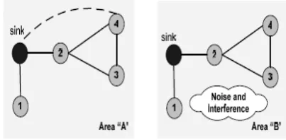
3.4 Cross Layer Design by Example
Assume that sensor nodes 1, 2, 3, 4, and sink node are distributed in area “A” and area “B” as shown in Figure 5. All these nodes are gathering environmental data and sending them to the sink node. Node 1 and 2 can send data directly to the sink node while node 3 and 4 use node 2 as a relay node to send their data. Assume that time-to-death of any of the nodes is the network lifetime. In area “A”, as node 2 sends its own data as well as relays data from node 3 and node 4 towards the sink node, so node 2 will drain its energy earlier, resulting in network lifetime of say T. If network layer of node 4 or node 3 gets to know about the energy level of node 2 frequently for routing decisions, it can notify link layer to increase the transmit power. In this way, node 2 will not be used as a relay node for node 3 and 4 and would save energy that was supposed to be utilized by node 2 for signal processing and relaying of messages. Node 3 and node 4 would directly send data to the sink node at cost of higher transmit power. In this way, T can be extended by cross layer information exchange between the routing and physical layers. In the second scenario, area “B” assumes that there is temporarily some noise and interference from external sources (e.g., microwaves).
In traditional approach, this would result in packet losses and re-transmissions if the signal to noise ratio (SNR) is below a certain threshold value. If node 4 increases it’s transmit power, so that the SNR value is above a certain threshold, packet losses and re-transmissions can be avoided. If application running on node 4 back’s off for some time and does not send data till the noise and interference level is acceptable (based on information from the link layer), it can save energy by avoiding transmissions and re-transmissions. In this way, the application layer based on cross layer information exchange with link layer can extend network lifetime T.
3. 5 Energy Consumption and Cross Layer Design Four major sources of energy wastage in MAC schemes are as follows. When two or more WSN nodes within each other’s transmission range transmit at the same time, collision occurs. Collision wastes energy because the collided packet becomes corrupt and requires re-transmission. Idle listening is another source of energy consumption, where a node listens to the channel hoping to receive some data. It can result in high energy wastage in event driven applications, where nodes are awake to relay data while no event occurs. Overhearing is third source of energy wastage, where nodes receives and analyze packets that have a different destination address. WSNs with high network degrees and heavy traffic are mostly affected by this phenomenon. The last source of energy wastage identified is control packet overhead. The following strategies can be adopted to decrease energy utilization at MAC sub-layer.
To turn on and off the radio to avoid idle listening and overhearing as is done in S-MAC or CSMA-MPS.
The use of a low power wake-up radio to wake-up the main radio can save significant amount of energy1.
Cross layering MAC and physical layer and using
adaptive transmit power can result in improved energy efficiency, delay, and reception rate.
Decrease in control packet overhead.
Reduce idle listening as in timeout MAC by adaptive duty cycling instead of fixed duty cycling.
Adaptive rate scheme with CSMA and backing off in application layer rather than MAC layer can be used to achieve fairness in an energy efficient way.
4.NETWORK SERVICE TYPES
The Internet today consists of thousands of access networks, which vary in scale from large wireline access networks, such as campus wide area networks or Internet Service Providers, supporting tens of thousands of users, to smaller wireless access networks supporting tens to hundreds of users. These access networks are interconnected by core networks (such as AT&T, WorldCom, or Sprint backbone networks) which support hundreds of millions of users. All of these networks primarily offer two types of services: guaranteed service and best effort service. In guaranteed service, the network provides some sort of service guarantee to individual users or groups of users. In best effort service, the network makes
no promises. This service is typically used by elastic traffic.
The classes of network service available are:
Minimum delay: Used when the time it takes for a datagram to travel from the source host to destination host (latency) is most important.
Maximum throughput: Used when the volume of data transmitted in any period of time is important.
Maximum reliability: Used when it is important that you have some certainty that the data will arrive at the destination without retransmission being required.
Minimum cost:Used when it is important to minimize the cost of data transmission.
.
5.SIMULATIONRESULT:
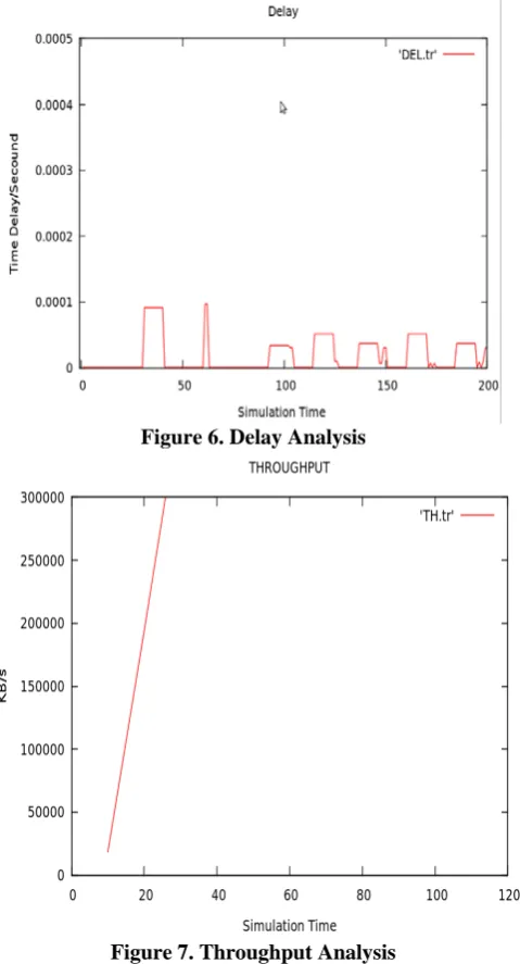
5.1 Throughput and Delay analysis without using any scheme :
With the simulation result, we can find out that throughput minimizes and delay maximized. We know, the classes of network services which are provided by the network layer are maximum throughput, minimum delay, minimum cost and maximum reliability required.
Figure 6. Delay Analysis
Figure 7. Throughput Analysis
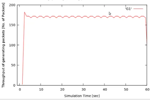
5.2 Throughput and Delay analysis using Modulation Techniques :
In this we implement the OFDM(Orthogonal Frequency Division Modulation) Technique, which is used to compress the large amount of data into a small amount. With OFDM we are using the three different modulation techniques as QAM (Quadrature Amplitude Modulation), QPSK (Quadrature Phase Shift Keying) & BPSK (Binary Phase Shift Keying) as shown in table 1.
Also in this we implement the scheduler. The data is destined to mobile users, and are temporarily buffered at the base-station.
Table 1: Modulation Techniques used with cyclic prefix.
Sr.
No. Profile Name Modulation Techniques
1 DIUC_PROFILE_1, UIUC_PROFILE_1 OFDM_BPSK_1_2
2 DIUC_PROFILE_2, UIUC_PROFILE_2 OFDM_QPSK_1_2
3 DIUC_PROFILE_3, UIUC_PROFILE_3 OFDM_QPSK_3_4
4 DIUC_PROFILE_4, UIUC_PROFILE_4 OFDM_16QAM_1_2
5 DIUC_PROFILE_5, UIUC_PROFILE_5 OFDM_16QAM_3_4
6 DIUC_PROFILE_6, UIUC_PROFILE_6 OFDM_16QAM_2_3
7 DIUC_PROFILE_7, UIUC_PROFILE_7 OFDM_16QAM_3_4
At each time t, the scheduler transmits to one of the mobile users based on the channel state(X1(t) X2(t) X3(t)), with each component taking one of two values: ON or OFF.
Figure 8: Packet data flows arrive from the Internet to the base-station.
With simulation result we can find out that throughput maximizes and delay minimizes as compared to the previous simulation result where we are not implementing any schemes.
Figure 9:Throughput Analysis
Figure 10. Delay Analysis
5.2 Throughput and Delay analysis using Cross Layer Design :
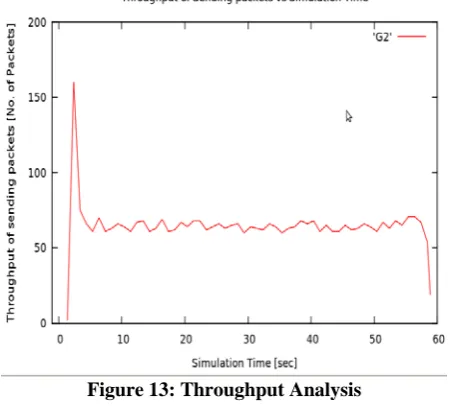
In this we are using cross layer design with multihop operation on WSN, i.e., we are making sensor nodes in active and sleep mode. This is shown in figure 13. When nodes are in active mode, then packet will send to the node. If nodes are in sleep mode then packets discarded or filter and aggregated with another packet. After some time, when node comes back in active mode then that packet delivered to the node.
Figure 11: Fig. multihop operation in a Proactive WSN. With simulation result we can find out that throughput maximizes and end-to-end delay minimizes as compared to the simulation result using modulation techniques.
Figure 13:Throughput Analysis
Figure 14. Delay Analysis
6. COMPARISONS :
For energy-constrained wireless networks, we can increase the network lifetime by using Cross Layer Design schemes with implementation of the following characteristics. Without using cross layer design, we can not implement this characteristics and can not increase the network lifetime.
(1) Multihop routing: In wireless environments the received power typically falls off as the mth power of
distance, with 2m . Hence, we can conserve transmission energy by using multihop routing .
(2) Load Balancing: If a node is on the routes of many source destination pairs, it will run out of energy very quickly. Hence, load balancing is necessary to avoid the creation of hot spots where some nodes die out quickly and cause the network to fail .
(3) Interference mitigation: Links that strongly interfere with each other should be scheduled at different times to decrease the energy consumption on these links .
(4) Frequency reuse: Weakly interfering links should be scheduled simultaneously so that each link can transmit at a lower rate when active. This reduces the average transmission power on each link.
(5) Redundant Data : By using multihop routing, we avoid the redundant data either by filtering and aggregating the redundant data.
(6) Throughput Analysis : Using cross layer design, it
increases the throughput as compared with the system without using cross layer design.
(7) Delay Analysis : Using cross layer design, it decreases
the delay as compared with the system without using cross layer design.
7. CONCLUSION :
In this, the WSN protocols with cross-layer design principles are implemented. We classify these studies in terms of interactions or modularity among physical (PHY), medium access control (MAC), routing, and transport layers.
In the first module we implement the base station & mobile station. In second module we implement the modulation techniques with scheduler. Also we have implemented MAC sublayer structure and the Physical layer with TCL configuration. And in the last module we implement the cross layer design. In all the module we have seen the simulation result with throughput and delay analysis. In the t we third module we have seen the simulation result of generated, send & received packets. With these implementations we are showing the simulation result for each implementation. And also we find out that the throughput maximizes and end-to-end delay minimizes using cross layer design as compared to the previous two implementations, i.e., implementation of base & mobile station and implementation of modulation techniques without cross layer design. Also using cross layer design, we can implement the some functions such as multihop routing, load balancing, interference mitigation, frequency reuse & discard redundant data. And also we can say, these functions can not be implemented without cross layer design.
REFERENCES :
[1] I. F. Akyildiz, W. Su, Y. Sankarasubramaniam, and E. Cayirci. Wireless sensor networks: a survey. Computer Networks, 38(4):393 – 422, December 2002.
[2] G. Bianchi. IEEE 802.11-saturation throughput analysis. IEEE
Communications Letters, 2(12):318–320, December 1998.
[3] C. F. Chiasserini and M. Garetto. An analytical model for wireless sensor networks with sleeping nodes. Mobile Computing, IEEE
Transactions on, 5:1706 – 1718, December 2006.
[4] T. V. Dam and K. Langendoen. An adaptive energy-efficient MAC protocol for wireless sensor networks. In Proceedings of the First
international conference on Embedded networked sensor systems,
pages 171–180, New York,USA, 2003.
[5] K. K. II and P. Mohapatra. Medium access control in wireless sensor networks. Computer Networks, 51(4):961–994, 2007.
[6] C. Y. Lin, W. C. Peng, Y. C. Tseng, Efficient In-Network Moving Object Tracking in Wireless Sensor Networks, IEEE Trans. on Mobile Computing, vol. 5, no. 8, 2006.
[7] W. Ye, J. Heidemann, D. Estrin, An Energy-Efficient MAC Protocol for Wireless Sensor Networks, in: Proc. of the 21st IEEE Infocom, 2002, pp. 1567-1576.
[8] Vincent S. Tseng, Kawuu W. Lin, Ming-Hua Hsieh, Energy Efficient Object Tracking in Sensor Networks by Mining Temporal Moving Pattern , in: IEEE International Conference on Sensor Networks, Ubiquitous, and Trustworthy Computing (SUTC’08), 2008. [9] ——, “Joint modulation and multiple access optimization under energy
constraints,” at Proceedings of Globecom’04, 2004.
10] Y. Awad, L. H. Crockett and R. W. Stewart, “OFDM TRANSCEIVER FOR IEEE 802.20 STANDARDS”,