An Integrated Source and Channel Rate Allocation
Scheme for Robust Video Coding and Transmission
over Wireless Channels
Jie Song
Media Connectivity Division, Agere Systems, Holmdel, NJ 07733, USA Email:[email protected]
K. J. Ray Liu
Electrical & Computer Engineering Department, University of Maryland, College Park, MD 20742, USA Email:[email protected]
Received 22 November 2002; Revised 3 September 2003
A new integrated framework for source and channel rate allocation is presented for video coding and transmission over wireless channels without feedback channels available. For a fixed total channel bit rate and a finite number of channel coding rates, the proposed scheme can obtain the near-optimal source and channel coding pair and corresponding robust video coding scheme such that the expected end-to-end distortion of video signals can be minimized. With the assumption that the encoder has the stochastic information such as average SNR and Doppler frequency of the wireless channel, the proposed scheme takes into ac-count robust video coding, channel coding, packetization, and error concealment techniques altogether. An improved method is proposed to recursively estimate the end-to-end distortion of video coding for transmission over error-prone channels. The pro-posed estimation is about 1–3 dB more accurate compared to the existing integer-pel-based method. Rate-distortion-optimized video coding is employed for the trade-offbetween coding efficiency and robustness to transmission errors.
Keywords and phrases:multimedia communications, joint source and channel coding, wireless video.
1. INTRODUCTION
Multimedia applications such as video phone and video streaming will soon be available in the third generation (3G) wireless systems and beyond. For these applications, delay constraint makes the conventional automatic repeat request (ARQ) and the deep interleaver not suitable. Feedback chan-nels can be used to deal with the error effects incurred in im-age and video transmission over error-prone channels [1], but in applications such as broadcasting services, there is no feedback channel available. In such cases, the optimal trade-offbetween source and channel coding rate allocations for video transmission over error-prone channels becomes very important. According to Shannon’s separation theory, these components can be designed independently without loss in performance [2]. However, this is based on the as-sumption that the system has an unlimited computational complexity and infinite delay. These assumptions are not satisfied in delay-sensitive real-time multimedia communi-cations. Therefore, it is expected that joint considerations of source and channel coding can provide performance im-provement [3,4].
propagation at the video decoder have been combined into a complete model of the entire video transmission system. However, the model for video encoder involves several pa-rameters and the model is not theoretically optimal because of the use of random MB intramode updating, which does not consider the different motion activities within a video frame to deal with error propagation. Furthermore, the mod-els depend on the distortion-parameter functions obtained through ad hoc numerical models and simulations over spe-cific video sequences, which also involves a lot of simulation efforts and approximation. The authors of [12] proposed an operational rate-distortion (RD) model for DCT-based video coding incorporating the MB intra–refreshing rate and an analytic model for video error propagation which has rel-atively low computational complexity and is suitable for real-time wireless video applications. Both methods in [11,12] focus on the statistical model optimization for general video sequence, which is not necessarily optimal for a specific video sequence because of the nonstationary behavior across diff er-ent video sequences.
In this paper, we propose an integrated framework to obtain, the near-optimal source and channel rate alloca-tion, and the corresponding robust video coding scheme for a given total channel bit rate with the knowledge of the stochastic characteristics of the wireless fading channel. We consider the video coding error (quantization and mode selection of MB), error propagation, and concealment ef-fects at the receiver due to transmission error, packetiza-tion, and channel coding in an integrated manner. The con-tributions of this paper are the following. First, we present an integrated system design method for wireless video com-munications in realistic scenarios. This proposed method takes into account the interactions of fading channel, chan-nel coding and packetization, and robust video coding in an integrated, yet simple way, which is an important sys-tem design issue for wireless video applications. Second, we propose an improved video distortion estimation which is about 1–3 dB peak signal-to-noise ratio (PSNR) more ac-curate than the original integer-pel-based method (IP) in [13] for half-pel-based video coding (HP), and the compu-tational complexity in the proposed method is less than that in [13].
The rest of the paper is organized as follows.Section 2 describes first the system to be studied, then the packetiza-tion and channel coding schemes used. We also derive the integrated relation between MB error probability and chan-nel coding error probability given the general wireless fad-ing channel information such as average signal-to-noise ra-tio (SNR) and Doppler frequency.Section 3presents the im-proved end-to-end distortion estimation method for HP-based video coding. Simulations are performed to com-pare the proposed method to the IP-based method in [13]. Then we employ RD-optimized video coding scheme to op-timize the end-to-end performance for each pair of source and channel rate allocation. Simulation results are shown in
Section 4to demonstrate the accuracy of the proposed
end-to-end distortion estimation algorithm under different chan-nel characteristics. Conclusions are stated inSection 5.
f
rs
ˆ f
rc
r
˜ f
H.263 encoder
Channel coder
Channel
Channel decoder H.263
decoder
Figure1: Joint source and channel video coding.
2. PROBLEM DEFINITION AND INTEGRATED SYSTEM STRUCTURE
The problem to be studied is illustrated inFigure 1which can be specified by five parameters (r,rc,ρ,fd,F):r is the total
channel bit rate,rcis the channel coding rate,ρis the
aver-age SNR at the receiver, fd is the Doppler frequency of the
fading channel targeted, andFis the video frame rate. H.263 [14] is used for video coding. A video sequence denoted as
fls, wheres=(x,y), 1≤x≤X, 1≤y≤Y, is the pixel
spa-tial location andl =1,. . .,Lis the frame index, is encoded at the bit raters = r×rcb/s and the frame rateFf/s with
the MB error probabilityPMb = f(ρ,fd,rc) that will be
de-tailed next. The resulted H.263 bitstream is packetized and protected by forward error correction (FEC) channel coding with the coding raterc. The resulted bitstream with raterb/s
is transmitted through wireless channels characterized byρ
and fd. The receiver receives the bitstream corrupted by the
channel impairment, then reconstructs the video sequence ˜
flsafter channel decoding, H.263 video decoding, and
pos-sible error concealment if residual errors occur. The end-to-end MSE between the input video sequence at the encoder and the reconstructed video sequence at the decoder is de-fined as
DE
rs,rc
= 1
XY L
X
x=1 Y
y=1 L
l=1
Efl(x,y)−f˜ (x,y) l
rs,rc 2
.
(1)
For the video system inFigure 1, there are two tasks to be per-formed with the five given system parameters (r,rc,ρ,fd,F).
First, we need to decide how to allocate the total fixed bit rate
r to the source raters =r×rc to minimize the end-to-end
MSE of the video sequence. Furthermore, the video encoder should be able to, for a source/channel rate allocation (rs,rc)
with residual channel decoding failure rate denoted aspw(rc),
select the coding mode and quantizer for each MB to mini-mize the end-to-end MSE of the video sequence. The goal is to obtain the source/channel rate pair (rs∗,rc∗)andthe
corre-sponding robust video coding scheme to minimize (1). In practical applications, there are only finite number of source/channel pairs available. We can find the robust video encoding schemes for each rate pair (rs,rc) that minimizes
D∗E(rs,rc), then the optimal source/channel rate pair (rs∗,rc∗)
and the corresponding video coding scheme can be obtained as
rs∗,rc∗
=argmin
(rs,rc)
DE∗
rs,rc
. (2)
For each pair (rs,rc), we use RD-optimized video coding
scheme to trade off between the source coding efficiency and robustness to error propagation. An improved recursive method which takes into account the interframe prediction, error propagation, and concealment effect is used to esti-mate the end-to-end MSE frame by frame. In this paper, the wireless fading channel is modeled as a finite-state Markov chain (FSMC) model [15,16, 17], and the Reed-Solomon (RS) code is employed for forward error coding.
2.1. Modeling fading channels using finite-state Markov chain
Gilbert and Elliott [15,16] studied a two-state Markov nel model, where each state corresponds to a specific chan-nel quality. This model provides a close approximation for the error rate performance of block codes on some noisy channels. On the other hand, when the channel quality varies dramatically such as in a fast Doppler spread, the two-state Gilbert-Elliott model becomes inadequate. Wang and Moayeri extended the two-state model to an FSMC model for characterizing the Rayleigh fading channels [17]. In [17], the received SNR is partitioned into a finite number of in-tervals. Denote by 0 = A0 < A1 < A2 < · · · < AK = ∞
the SNR thresholds of different intervals, then if the received SNR is in the interval [Ak,Ak+1),k∈ {0, 1, 2,. . .,K−1}, the fading channel is said to be in state Sk. It turns out that if
the channel changes slowly and is properly partitioned, each state can be considered as a steady state, and a state transition can only happen between neighboring states. As a result, a fading channel can be represented using a Markov model if given the average SNRρand Doppler frequency fd.
2.2. Performance analysis of RS code over finite-state Markov channel model
RS codes possess maximal minimum distance properties which make them powerful in correcting errors with arbi-trary distributions. For RS symbols composed ofmbits, the encoder for an RS(n,k) code groups the incoming bitstream into blocks ofkinformation symbols and appendsn−k re-dundancy symbols to each block. So the channel coding rate is rc = k/n. For an RS(n,k) code, the maximal number of
symbol errors that can be corrected ist= (n−k)/2. When the number of symbol errors is more thant, RS decoder re-ports a flag to notify that the errors are uncorrectable. The probability that a block cannot be corrected by RS(n,k), de-noted as a decoding failure probability pw(n,k), can be
cal-culated as
pw(n,k)= n
m=t+1
P(n,m), (3)
where P(n,m) denotes the probability ofm symbol errors within a block ofnsuccessive symbols. The computation of
P(n,m) for FSMC channel model has been studied before (see [16,18]).
2.3. Packetization and macroblock error probability computation
We use baseline H.263 video coding standard for illustration. H.263 GOB/slice structure is used where each GOB/slice is encoded independently with a header to improve resynchro-nization. Denoting by Nsthe number of GOB/slice in each
frame, the RS(n,k) code block sizen(bytes) is set to
n=
r
8·F·Ns
(4)
such that each GOB/slice is protected by an RS codeword in average, wherexis the smallest integer larger thanx. No further alignment is used. In case of decoding failure of an RS codeword, the GOBs (group of blocks) covered by the RS code will be simply discarded and followed by error conceal-ment. If a GOB is corrupted, the decoder simply drop the GOB and performs a simple error concealment as follows: the motion vector (MV) of a corrupted MB is replaced by the MV of the MB in the GOB above. If the GOB above is also lost, the MV is set to zero, then the MB is replaced by the corresponding MB at the same location in the previous frame. To facilitate error concealment at the decoder when errors occur, the GOBs which are indexed by even numbers are concatenated together, followed by concatenated GOBs indexed by odd numbers. By using this alternative GOB orga-nization, the neighboring GOBs are normally not protected within the same RS codeword. Thus, when a decoding fail-ure occurs in one RS codeword, the neighboring GOBs will not be corrupted simultaneously, which helps the decoder to perform error concealment using the neighboring correctly received GOB.
In order to estimate the end-to-end distortion, we need to model the relation between video MB error probability
PMB(n,k) and RS(n,k) decoding failure probabilitypw(n,k),
that is,
PMB(n,k)≈α·pw(n,k). (5)
Since no special packetization or alignment is used, one RS codeword may contain part of one GOB/slice or overlap more than one GOB/slice. It is difficult to find the exact re-lation betweenPMB(n,k) and pw(n,k) because the length of
GOB in each frame is varying. Intuitively, αshould be be-tween 1 and 2. Experiments are performed to find the
suit-able α. Figure 2shows the experiment results of RS
code-word failure probability and GOB error probability over Rayleigh fading channels. It turns out thatα≈1.5 is a good approximation in average. For a source and channel code pair (rs,rc) or RS(n,k), the channel code decoding failure
proba-bility pw(n,k) can be derived fromρand fd as described in
0.12 0.11 0.1 0.09 0.08
E
rro
r
p
ro
b
ab
il
it
y
0.07 0.06 0.05 0.04 0.03
0.3 0.4 0.5 0.6 0.7 0.8
WER GOB loss 1.5×CFR
RS code rate
(a)
0.12 0.1 0.08
Er
ro
r
p
ro
babilit
y
0.06 0.04 0.02 0
0.3 0.4 0.5 0.6 0.7 0.8
WER GOB loss 1.5×CFR
RS code rate
(b)
Figure2: Simulated RS codeword failure rate (CFR), GOB loss rate, and the values of 1.5 + WER. (a) Rayleigh fading, SNR=18 dB, QPSK,
and f d=10 Hz.(b) Rayleigh fading, SNR=18 dB, QPSK,f d=100 Hz.
and an RD-optimized scheme are employed to estimate the minimal end-to-end MSE of the video sequence and obtain the corresponding optimized video coding scheme, which is to be described in detail in the next section.
3. OPTIMAL DISTORTION ESTIMATION AND MINIMIZATION
We first describe the proposed distortion estimation method for both HP- and IP-based video coding over error-prone channels. Simulations are performed to demonstrate the im-proved performance of the proposed method. Then an RD framework is used to select the coding mode and quantizer for each MB to minimize the estimated distortion, given the source raters,PMBwhich is derived as inSection 2, and the frame rateF.
3.1. Optimal distortion estimation
Recently, modeling of error propagation effects have been considered in order to optimally select the mode for each MB to trade offthe compression efficiency and error robustness [11,13,19]. In particular, a recursive optimal per-pixel es-timate (ROPE) of decoder distortion was proposed in [13] which can model the error propagation and quantization dis-tortion more accurately than other methods. But the method in [13] is only optimal for the IP-based video coding. For the HP case, the computation of spatial cross correlation be-tween pixels in the same and different MBs is needed to ob-tain the first and second moments of bilinear interpolated HPs, the process is computationally prohibitive. Most of the current video coding use the HP-based method to improve
the compression performance. We propose a modified recur-sive estimate of end-to-end distortion that can take care of both IP- and HP-based video coding.
The expected end-to-end distortion for the pixelfs l ats=
(x,y) in framelis
ds l =E
fs l −f˜ls
2
=Efs
l −fˆls+ ˆfls−f˜ls 2
=fls−fˆls 2
+ 2fls−fˆls
Efˆls−f˜ls
+Efˆls−f˜ls 2
, (6)
where ˆfs
l is the quantized pixel value atsin framel. Denote
es
l = fls−fˆlsas the quantization error, ˆe s,v
l = fˆls−fˆl−s−v1 as the motion compensation error using MVv, and ˜esl = fˆls− f˜ls
as the transmission and error-propagation error. Assuming that ˜es
lis an uncorrelated random variable with a zero mean,
which is a reasonable assumption whenPMBis relatively low as will be shown in the simulations later, we have
dls=
esl 2
+Ee˜sl 2
. (7)
We derive a recursive estimate ofE{(˜esl)2}for intra-MB and
inter-MB as follows.
Intramode MB
The following three cases are considered.
(1) With the probability 1−PMB, the intra-MB is received correctly and then ˆfs
(2) With the probability (1−PMB)PMB, the intra-MB is lost but the MB above is received correctly. Denoting by
vc=(xc,yc) the MV of the MB above, two cases of
er-ror concealment are considered depending on whether
vcis at the HP location or not.
(i) Ifvc is at the IP location, we have ˜fls = f˜l−s−vc1 . Then after error concealment,
˜
The clipping effect is ignored in the computa-tion.
(ii) Ifvc is at the HP location, without loss of
gen-erality, assume thatvc = (xc,yc) is at HP
loca-tion that is interpolated from four neighbour-ing IP locations with MVs: v1
c = (xc,yc),
v2
c = (xc,yc), v3c = (xc,yc), and vc4 =
(xc,yc), where xc and xc denote the
largest integer that is smaller than xc and the
smallest integer larger thanxc, respectively. We
have ˜fls=( ˜f
(3) With the probabilityP2
MB, both the current MB and the MB above are lost. The MB in the previous video frame at the same location is repeated, that is,vc=0=(0, 0):
Combining all of the cases together, we have the following results.
When an intermode MB is correctly received with the proba-bility 1−PMB, the motion compensation error ˆesl =fˆls−fˆl−s−v1 and the MV vare received correctly and are reconstructed from the previous reconstructed frame at the decoder. We again consider two cases depending on whetherv=(x,y) is at the IP or HP location.
(1) Ifvis at the IP location, then ˜fls=eˆls+ ˜fl−s−v1 and
dimensions, the prediction is interpolated from four pixels with MVs: v1 = (x,y), v2 = (x,y),
34
Figure3: Comparison between HP- and IP-based distortion estimation in the HP video coding case (a) Foreman:r=300 kbps, f=30 f/s,
andPMB=0.1. (b) Salesman:r=300 kbps,f =30 f/s, andPMB=0.1.
The encoder can use the above procedures to recursively esti-mate the expected distortionds
l in (7), based on the
accumu-lated coding and error propagation effects from the previous video frames and current MB coding modes and quantizers. To implement the HP-based estimation, the encoder needs to store an image forE{(˜es
l)2}; for the locations in which
ei-therxoryis at HP, the value is obtained by scaling the sum of the neighboring two values by 1/4, and for locations in which both x and yare at HP precision, it is obtained by scaling the sum of the neighboring four values by 1/16. It should be noted that the scaling by 1/4 or 1/16 can be done by simple bitshift. Both IP- and HP-based estimations need the same memory size to store either two IP images,E{fl}
andE{fl2}, or one HP image,E{(˜els)2}, butE{(˜esl)2}requires
smaller bitwidth/pel since it is an error signal instead of a pixel value. The HP-based computational complexity is less than the IP-based method since it only needs to compute
E{(˜es
l)2}instead of computing bothE{fl}andE{fl2}in the
IP-based estimate.
We now compare the accuracy of the proposed HP-based estimation to the original IP-based method (ROPE) in [13]. In the simulation, each GOB is carried by one packet. So the packet loss rate is equivalent to the MB error probability
PMB. A memoryless packet loss generator is used to drop the packet at a specified loss probability. QCIF sequences Fore-man andSalesman are encoded by the Telenor H.263 en-coder with the intra-MB fresh rate set to 4, that is, each MB is forced to be intramode coded if it has not been intracoded for consecutive four frames. The HP- and IP-based estimates are compared to the actual decoder distortion averaged over 50 different channel realizations.
In Figure 3a, the sequence Foreman of 150 frames is
32
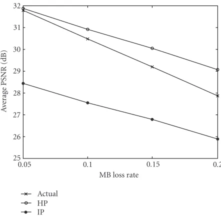
Figure4: Average PSNR versus MB loss rate for HP- and IP-based
distortion estimation; Foreman:r=300 kb/s and f =30 f/s.
300 Kbps, frame rate of 30 f/s, and MB loss rate of 10%. In
Figure 3b, the sequence Salesman is encoded in the same way.
It can be noted that the HP-based estimation is more accu-rate to estimate the actual distortion at the decoder compared to the IP-based estimation. Figure 4also shows the average PSNR of the 150 coded frames with respect to MB loss rates from 5% to 20%. When MB loss rate is as small as 5%, the HP-based estimation is almost the same as the actual distor-tion, while the IP-based method has about 3 dB difference. The results is as expected since there is about 2–4 dB PSNR difference between HP- and IP-based video coding efficiency given the same bit rate. As the MB loss rate increases as large as 20%, the HP-based estimation is about 1 dB better than the actual distortion, while the IP-based estimation is about 2 dB worse. So the HP-based method is still 1 dB more ac-curate than the IP-based method. The reason is that the er-ror propagation effects play a more significant role when MB loss rate gets larger, so the coding gain of the HP-based mo-tion compensamo-tion is reduced. Also, the assumpmo-tion in HP-based method that the transmission and propagation errors are not correlated and zero mean may become loose. For practical scenarios, it is demonstrated that the HP-based esti-mation outperforms the original IP-based method by about 1–3 dB.
3.2. Rate-distortion-optimized video coding
The quantizer step size and code mode for each MB in a frame is optimized by an RD framework. Denote by bi,j,l
Q ×M is the set of all admissible encoding vectors. For each source/channel pair (rs,rc), we have the corresponding
PMB(n,k) from (5). The encoder needs to determine the cod-ing mode and quantizer for each MB in totalLframes to min-imize the end-to-end MSEDE(rs,PMB) of the video sequence, which is defined as
DE
where Rl is the number of bits used to encode framel, its
maximal value is denoted as Rmax
l = rs/F+∆lwhich is the
maximal number of bits available to encode framelprovided by a frame level rate control algorithm with averagers/Fand
buffer related variable∆l. MoreoverDl(Rl,PMB) is the
esti-Since there is dependency between neighboring interframes because of the motion compensation, the optimal solution of (17) has to be searched overCH×V×L, which is computa-tionally prohibitive. We use greedy optimization algorithm, which is also implicitly used in most JSCC video coding methods such as [10,11,13], to find the coding modes and quantizers for MBs in frame l that minimize Dl(Rl,PMB), then find coding modes and quantizers for MBs in frame
l+1 that minimizeDl+1(Rl+1,PMB) based on the previous op-timized framel, and so on. The optimal pair (rs∗,rc∗) and the
corresponding optimal video coding scheme can be found such that
The goal now is to optimally select the quantizers and encod-ing modes on the MB level for a specific MB error ratePMB and frame rateRmaxl to trade offthe source coding efficiency
and robustness to error. The notation of PMB and (rs,rc) is
dropped from now on unless needed.
The optimal coding problem for framelcan be stated as
Rl= H
i=1 V
j=1
Rcl,i,j
≤Rmaxl . (22)
Such RD-optimized video coding schemes have been studied for noiseless and noisy channels recently [19,20,21, 22,23, 24]. Using Lagrangian multiplier, we can solve the problem by minimizing
Jl(λ)=Dl+λRl, (23)
where λ ≥ 0. For video coding over error-prone
chan-nels, GOB coding structure is used for H.263 video coding over noisy channels with each GOB encoded independently. Therefore, if the transmission errors occur in one GOB, the errors will not propagate into other GOBs in the same video frame.
For video coding over noiseless channels, the indepen-dent GOB structure leads to the fact that the optimization of (23) can be performed for each GOB separately. How-ever, when considering RD-optimized video coding for noisy channels, the MB distortionDi,j(ci,j,PMB) depends not only on the mode and quantizer of the current MB but also on the mode of the MB above to take into account error conceal-ment distortion. Therefore, there is a dependency between neighboring GOBs for this optimization problem. We use greedy optimization algorithm again to find the solution by searching the optimal modes and quantizers from the first GOB to the last GOB in each frame.
4. SIMULATION RESULTS
We first use a simple two-state Markov chain model for sim-ulation to show the performance of the integrated source and channel rate allocation and robust video coding scheme, where the given channel stochastic knowledge is accurate. Then simulations over Rayleigh fading channel is performed to verify the effectiveness of the proposed scheme for practi-cal wireless channels.
4.1. Two-state Markov chain channel
Simulations have been performed using base mode H.263 to verify the accuracy of the proposed integrated scheme. In the simulations, the total channel signaling rater equals 144 kbps, which is a typical rate provided in the 3G wireless systems. Video frame rate isF =10 f/s. The video sequence used for simulation is Foreman in QCIF format. RS code over
GF(28) is used for FEC. The channel coding rate used are
{0.2, 0.3, 0.4, 0.5, 0.6, 0.7, 0.8}. The source and channel cod-ing ratesrs,rcand the corresponding RS code (n,k) are listed
inTable 1. A two-state Markov channel model [16] is used,
where the state transition is at the RS symbol level. The two states of the model are denoted byG(good) andB(bad). In stateG, the symbols are received correctly (eg =0) whereas
in stateB, the symbols are erroneous (eb=1). The model is
fully described by the transition probabilities pfrom stateG
to stateB, andqfrom stateBto stateG. We use the
probabil-ity of stateB:
PB= p
p+q, (24)
and the average bursty length:
LB= 1
q, (25)
which is the average number of consecutive symbol errors to model the two-state Markov model [11,16].
The simulations are performed through the following steps.
(i) For each channel coding raterc (or RS(n,k)) in each
column ofTable 1, the RS code decoding failure rate
pw(n,k) is computed using (3) for a given two-state
Markov channel model. The results for differentrcand
channel models are shown inTable 2.
(ii) The corresponding video MB error ratePMB(rc) is
ob-tained using (5), whereα=1.5.
(iii) For each source raters =r×rc and the
correspond-ing PMB(rc), the RD-optimized H.263 video coding
is employed while estimating the end-to-end MSE
DE∗(rs,rc).
(iv) The H.263 bitstream is packetized and protected us-ing RS(n,k), and then transmitted over the two-state Markov channel model.
(v) The receiver receives the bitstream, reconstructs the video sequence after the FEC decoding, and performs the H.263 decoding and possible error concealment if errors occur. The distortion for each simulation run between the original video sequence and the recon-structed video sequence at the receiver is also com-puted.
The average estimated PSNR, PSNRE, of video signals is
used to measure the performance:
PSNRE
rs,rc
=1
L
L
l=1
PSNRlErs,rc
, (26)
where
PSNRlErs,rc
=10 log10 255 2
D∗E
rs,rc
(27)
is the estimated average PSNR between the original framel
and the corresponding reconstruction at the decoder using the pair (rs,rc), andD∗E(rs,rc) is the minimal estimated
end-to-end MSE from (17) through RD-optimized video coding. The average PSNR ofNruns of simulation is defined as
PSNRS
rs,rc
= 1
N
N
n=1 1
L
L
l=1
PSNR(Sn,l)
rs,rc
, (28)
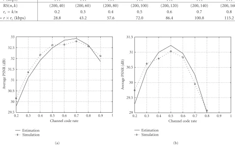
Table1: The source and channel rates used in simulation.
r(kbps) 144 144 144 144 144 144 144
RS(n,k) (200, 40) (200, 60) (200, 80) (200, 100) (200, 120) (200, 140) (200, 160)
rc=k/n 0.2 0.3 0.4 0.5 0.6 0.7 0.8
rs=r×rc(kbps) 28.8 43.2 57.6 72.0 86.4 100.8 115.2
33 32.5 32 31.5 31
A
ver
age
P
SNR
(dB)
30.5 30 29.5
0.2 0.3 0.4 0.5 0.6 0.7 0.8 0.9 1
Estimation Simulation
Channel code rate
(a)
31.5
31
30.5
30
29.5
A
ver
age
P
SNR
(dB)
29
0.2 0.3 0.4 0.5 0.6 0.7 0.8 0.9 1
Estimation Simulation
Channel code rate
(b)
Figure5: Average PSNR obtained by estimation versus simulation using two-state Markov model. (a) Symbol error rate =0.01, where
PB=0.01 andLB=16. (b) Symbol error rate=0.05, wherePB=0.05 andLB=16.
frame l and the corresponding reconstruction at the de-coder in the nth simulation using the source/channel rate pair (rs,rc).
Figure 5ashows the average estimated PSNREof the
op-timal rate allocation and robust video coding for different channel code rates when the symbol error rate isPB =0.01
and the bursty lengthLB=16 symbols, and the
correspond-ing average simulated PSNRSis of 50 times video
transmis-sion. Figure 5balso shows the same comparison when the symbol error rate isPB=0.05. It can be noted that the
esti-mated PSNRE, which is obtained at the encoder during
RD-optimized video encoding, matches the simulated PSNRS
very well. The optimal source and channel rate pair can also be found through Figures 5aand5b for different channel characteristics. The corresponding channel decoding failure rate of the optimal channel coding rates in Figures5aand5b are 0.018 and 0.034, respectively.
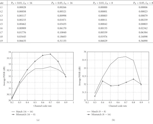
We also compare the performance when the knowledge of channel model used at video encoder does not match the real channel used in simulations.Figure 6shows two cases of channel mismatch. InFigure 6a, the video stream, which is encoded based onPB =0.01 andLB =16 two-state Markov
channel, is simulated using two-state Markov channel with
PB =0.01 andLB =8. The simulated average PSNR is
bet-ter than the average PSNR estimated at the encoder during encoding because the channel model used in estimation is worse than the model used in simulation. On the other hand, when the video stream, which is encoded based onPB=0.01
andLB = 8 two-state Markov channel, is simulated using
two-state Markov channel with PB = 0.01 and LB = 16,
the simulated average PSNR is much worse than the aver-age PSNR estimated at the encoder as shown in Figure 6b. Furthermore, the optimal source and channel coder pair ob-tained at the encoder is not optimal when the channel con-dition used in simulation is worse than the channel infor-mation used at the encoder. This simulation result suggests that the optimal rate allocation and video coding should be focused on the worse channel conditions for broadcasting services.
4.2. Rayleigh fading channel
Table2: The Reed-Solomon code decoding failure rate.
Rate PB=0.01,LB=16 PB=0.05,LB=16 PB=0.01,LB=8 PB=0.05,LB=8
0.1 0.00028 0.00266 0.00000 0.00006
0.2 0.00058 0.00521 0.00001 0.00023
0.3 0.00117 0.00998 0.00003 0.00079
0.4 0.00233 0.01871 0.00011 0.00259
0.5 0.00462 0.03435 0.00042 0.00803
0.6 0.00909 0.06170 0.00155 0.02342
0.7 0.01776 0.10840 0.00559 0.06384
0.8 0.03445 0.18603 0.01976 0.16098
0.9 0.06635 0.31135 0.06829 0.36890
34 33.5 33 32.5 32
A
ver
age
P
SNR
(dB)
31.5 31 30.5 30
0.2 0.3 0.4 0.5 0.6 0.7 0.8 0.9 1
Match (16→16) Mismatch (16→8)
Channel code rate
(a)
34 33.5 33 32.5 32
A
ver
age
P
SNR
(dB)
31.5 31
0.2 0.3 0.4 0.5 0.6 0.7 0.8 0.9 1
Match (8→8) Mismatch (8→16)
Channel code rate
(b)
Figure6: Average PSNR obtained in channel mismatch cases. (a) Error burst is shorter than that used in estimation. (b) Error burst is longer
than that used in estimation.
selected in such a way that the probability that the channel gain is at statesk,k=0, 1,. . .,K−1, is
p0= 2
K(K+ 1),
pk=k p0, k=1, 2,. . .,K−1.
(29)
The FSMC state transition is described at the RS codeword symbol level (8-bit RS symbol) with the assumption that the four QPSK modulation symbols within an RS codeword symbol stay in the same FSMC state. Given the average SNRρ
and the Doppler frequency fd, we can obtain the parameters
such as steady state probabilitypk, RS symbol error
probabil-ityek, and state transition rates [17]. Then following the
pro-cedures described inSection 2.1, we are able to analyze the RS code performance over Rayleigh fading channels.Table 3
shows the estimated RS code decoding failure probability us-ing FSMC model and the simulation values when the SNR is 18 dB and the Doppler frequency is 10 Hz and 100 Hz, re-spectively. The RS codeword error rate obtained by the FSMC matches the simulation results very well when fd is 10 Hz.
When fdis 100 Hz, the FSMC-based estimate is not as
accu-rate as the results when fdis 10 Hz, but is still within
accept-able range compared to the simulated values.
Figure 7ashows the average estimated PSNREand
simu-lated PSNRSof the video coding after optimal rate allocation
and robust video coding for different channel code rates when the SNR is 18 dB and fdis 10 Hz.Figure 7balso shows
the comparison when the f dis 100 Hz. Even though it can be noted that there are about 1 dB difference between the es-timated PSNREand the simulated PSNRS, the near-optimal
31 30 29 28
A
ver
age
P
SNR
(dB)
27 26 25
0.2 0.3 0.4 0.5 0.6 0.7 0.8 0.9 1
Estimation Simulation
Channel code rate
(a)
33 32 31 30 29
A
ver
age
P
SNR
(dB)
28 27 26 25
0.2 0.3 0.4 0.5 0.6 0.7 0.8 0.9 1
Estimation Simulation
Channel code rate
(b)
Figure7: Average end-to-end PSNR obtained by estimation versus simulation for Rayleigh fading channels: (a) SNR=18 dB, fd=10 Hz,
and (b) SNR=18 dB,fd=100 Hz.
33 32 31
A
ver
age
P
SNR
(dB)
30 29 28 27
0.2 0.3 0.4 0.5 0.6 0.7 0.8 0.9 1
10 Hz→10 Hz 10 Hz→100 Hz
Channel code rate
(a)
33 32 31
A
ver
age
P
SNR
(dB)
30 29 28 27 26
0.2 0.3 0.4 0.5 0.6 0.7 0.8 0.9 1
100 Hz→100 Hz 100 Hz→10 Hz
Channel code rate
(b)
Figure8: Average end-to-end PSNR over Rayleigh fading Channels: (a) SNR=18 dB, fdused for estimation at the encoder is 10 Hz, and
(b)SNR=18 dB,fdused for estimation at the encoder is 100 Hz.
rc) obtained from the estimation (0.8 and 0.5 as shown in
Figure 7) still has the maximal simulated end-to-end PSNR
over Rayleigh fading channels. The simulation results verify the effectiveness of the proposed scheme to obtain the opti-mal source and channel coding pair when given a fixed total bit rate for wireless fading channels.
Experiments are also performed when the knowledge of channel Doppler frequency used at the video encoder does not match the actual Doppler frequency used in simulations.
Figure 8shows two cases of channel mismatch. InFigure 8a,
the video bitstream which is encoded based on fd =10 Hz
Table3: Analysis and simulation values of the RS code decoding failure probability for the Rayleigh fading channel with SNR equals 18 dB and the Doppler frequencyfdequals 10 and 100 Hz.
fd=10 Hz fd=100 Hz
Code rate FSMC model Simulation FSMC model Simulation
0.2 0.0430 0.0391 0.0098 0.0044
0.3 0.0482 0.0464 0.0170 0.0072
0.4 0.0536 0.0555 0.0282 0.0119
0.5 0.0593 0.0650 0.0450 0.0181
0.6 0.0653 0.0772 0.0692 0.0280
0.7 0.0717 0.0915 0.1032 0.0526
0.8 0.0815 0.1085 0.1499 0.1110
0.9 0.1240 0.1333 0.2131 0.2856
of 10 Hz and 100 Hz, separately. InFigure 8b, the video bit-stream which is encoded based on fd =100 Hz is simulated
over fading channels with Doppler frequency of 100 Hz and 10 Hz, separately. In both scenarios, the video quality would be better if the actual condition in terms of MB loss rate is smaller than the knowledge used at the encoder, and would be worse otherwise. Furthermore, the optimal source and channel coder pair obtained at the encoder is not optimal when the channel condition used in simulation is worse than the channel information used at the encoder. This simula-tion result again suggests that the optimal rate allocasimula-tion and video coding should be focused on the worse channel condi-tions for broadcasting services.
5. CONCLUSION
We have proposed an integrated framework to find the near-optimal source and channel rate allocation and the cor-responding robust video coding scheme for video coding and transmission over wireless channels when there is no feedback channel available. Assuming that the encoder has the stochastic channel information when the wireless fading channel is modeled as an FSMC model, the proposed scheme takes into account the robust video coding, packetization, channel coding, error concealment, and error propagation effects altogether. This scheme can select the best source and channel coding pair to encode and transmit the video sig-nals. Simulation results demonstrated the optimality of the rate allocation scheme and accuracy of end-to-end MSE esti-mation obtained at the encoder during the process of robust video encoding.
REFERENCES
[1] B. Girod and N. Farber, “Feedback-based error control for mobile video transmission,” Proceedings of the IEEE, vol. 87, no. 10, pp. 1707–1723, 1999.
[2] T. M. Cover and J. A. Thomas, Elements of Information The-ory, Wiley Series in Communications. John Wiley & Sons, NY, USA, 1991.
[3] J. Modestino and D. G. Daut, “Combined source-channel coding of images,” IEEE Trans. Communications, vol. 27, pp. 1644–1659, November 1979.
[4] N. Tanabe and N. Farvardin, “Subband image coding using entropy-coded quantization over noisy channels,” IEEE Jour-nal on Selected Areas in Communications, vol. 10, no. 5, pp. 926–943, 1992.
[5] N. Farvardin and V. Vaishampayan, “On the performance and complexity of channel-optimized vector quantizers,” IEEE Transactions on Information Theory, vol. 37, no. 1, pp. 155– 160, 1991.
[6] G. Cheung and A. Zakhor, “Bit allocation for joint source/ channel coding of scalable video,” IEEE Trans. Image Process-ing, vol. 9, no. 3, pp. 340–356, 2000.
[7] M. Bystrom and J. W. Modestino, “Combined source-channel coding schemes for video transmission over an additive white Gaussian noise channel,” IEEE Journal on Selected Areas in Communications, vol. 18, no. 6, pp. 880–890, 2000.
[8] R. E. V. Dyck and D. J. Miller, “Transport of wireless video us-ing separate, concatenated, and joint source-channel codus-ing,”
Proceedings of the IEEE, vol. 87, no. 10, pp. 1734–1750, 1999. [9] Y. Wang, S. Wenger, J. Wen, and A. K. Katsaggelos, “Error
re-silient video coding techniques,”IEEE Signal Processing Mag-azine, vol. 17, no. 4, pp. 61–82, 2000.
[10] M. Gallant and F. Kossentini, “Rate-distortion optimized lay-ered coding with unequal error protection for robust internet video,”IEEE Trans. Circuits and Systems for Video Technology, vol. 11, no. 3, pp. 357–372, 2001.
[11] K. Stuhlmuller, N. Farber, M. Link, and B. Girod, “Analysis of video transmission over lossy channels,” IEEE Journal on Selected Areas in Communications, vol. 18, no. 6, pp. 1012– 1032, 2000.
[12] Z. He, J. Cai, and C. W. Chen, “Joint source channel rate-distortion analysis for adaptive mode selection and rate con-trol in wireless video coding,”IEEE Trans. Circuits and Systems for Video Technology, vol. 12, no. 6, pp. 511–523, 2002. [13] R. Zhang, S. L. Regunathan, and K. Rose, “Video coding with
optimal inter/intra mode switching for packet loss resilience,”
IEEE Journal on Selected Areas in Communications, vol. 18, no. 6, pp. 966–976, 2000.
[14] ITU-T, “H.263, video coding for low bitrate communication,” February 1998.
[15] E. N. Gilbert, “Capacity of a burst-noise channel,”Bell System Technical Journal, vol. 39, no. 5, pp. 1253–1265, 1960. [16] E. O. Elliott, “Estimates of error rates for codes on burst-noise
channels,” Bell System Technical Journal, vol. 42, pp. 1977– 1997, September 1963.
[17] H. Wang and N. Moayeri, “Finite-state Markov channel—a usefulmodel for radio communication channels,”IEEE Trans. Vehicular Technology, vol. 44, no. 1, pp. 163–171, 1995. [18] J. Lu, K. B. Letaief, and M. L. Liou, “Robust video
transmis-sion over correlated mobile fading channels,”IEEE Trans. Cir-cuits and Systems for Video Technology, vol. 9, no. 5, pp. 737– 751, 1999.
[19] G. Cote, S. Shirani, and F. Kossentini, “Robust H.263 video communication over mobile channels,” inIEEE Proc. of Inter-national Conference on Image Processing, pp. 535–539, Kobe, Japan, October 1999.
[23] G. J. Sullivan and T. Wiegand, “Rate-distortion optimization for video compression,”IEEE Signal Processing Magazine, vol. 15, no. 6, pp. 74–90, 1998.
[24] T. Wiegand, M. Lightstone, D. Mukherjee, T. G. Campbell, and S. Mitra, “Rate-distortion optimized mode selection for very low bit-rate video coding and the emerging H.263 stan-dard,” IEEE Trans. Circuits and Systems for Video Technology, vol. 6, no. 2, pp. 182–190, 1996.
Jie Songreceived his B.S. degree from Bei-jing University, BeiBei-jing, China, in 1990, his M.S. degree from Beijing University of Posts and Telecommunications, Beijing, China, in 1993, and his Ph.D. degree from the Uni-versity of Maryland, College Park, Md, in 2000, all in electrical engineering. From April 1993 to June 1996, he was a Lecturer and a Researcher in the Information En-gineering Department at Beijing University
of Posts and Telecommunications. He worked for Fujitsu Labs of America, Calif, in the summer of 1997. From November 1997 to February 1999, he was a part-time Consultant of multimedia tech-nologies in Odyssey Techtech-nologies Inc., Jessup, Md, where he was in-volved in the projects of H.323/H.324 videophone, portable multi-media terminal design, and multichannel video capturing systems. Since August 2000, he has been working on research, design, and implementation for broadband and satellite communication sys-tems at Agere Syssys-tems (formerly Microelectronics Group, Lucent Technologies). His research interests include signal processing for digital communication and multimedia communications.
K. J. Ray Liureceived the B.S. degree from the National Taiwan University in 1983, and the Ph.D. degree from UCLA in 1990, both in electrical engineering. He is a Professor at the Electrical and Computer Engineering Department and Institute for Systems Re-search of the University of Maryland, Col-lege Park. His research contributions en-compass broad aspects of signal process-ing algorithms and architectures;