Copyright to IJIRSET www.ijirset.com 7834
ISSN: 2319-8753
I
nternational
J
ournal of
I
nnovative
R
esearch in
S
cience,
E
ngineering and
T
echnology
(An ISO 3297: 2007 Certified Organization)
Vol. 2, Issue 12, December 2013
Thermal Analysis and Optimization of I.C.
Engine Piston Using Finite Element Method
S. Srikanth Reddy
1, Dr. B. Sudheer Prem Kumar
2M.Tech Student, Department of Mechanical Engineering, JNTU College of Engineering Hyderabad, Andhra Pradesh, India1.
Professor, Head of the Department, Department of Mechanical Engineering, JNTU College of Engineering Hyderabad, Andhra Pradesh, India2.
Abstract: In this study, firstly, thermal analyses are investigated on a conventional (uncoated) diesel piston, made of aluminium silicon alloy for design 1 and design 2 parameters. Secondly, thermal analyses are performed on piston, coated with Zirconium material by means of using a commercial code, namely ANSYS. The effects of coating on the thermal behaviours of the pistons are investigated. The finite element analysis is performed by using computer aided design software. The main objective is to investigate and analyze the thermal stress distribution of piston at the real engine condition during combustion process. This thesis describes the mesh optimization by using finite element analysis technique to predict the higher stress and critical region on the component.
In this work, the main emphasis is placed on the study of thermal behaviour of functionally graded coatings obtained by means of using a commercial code, ANSYS on aluminium and zirconium coated aluminium piston surfaces. The analysis is carried out to reduce the stress concentration on the upper end of the piston i.e. (piston head/crown and piston skirt and sleeve). With using computer aided design NX/Catia software the structural model of a piston will be developed. Furthermore, the finite element analysis is done using Computer Aided Simulation software ANSYS.
Key words: Ansys, FEA, Piston crown, Piston skirt, CAD, stress concentration, Thermal analysis etc.
I. INTRODUCTION
Copyright to IJIRSET www.ijirset.com 7835
ISSN: 2319-8753
I
nternational
J
ournal of
I
nnovative
R
esearch in
S
cience,
E
ngineering and
T
echnology
(An ISO 3297: 2007 Certified Organization)
Vol. 2, Issue 12, December 2013
Understanding this, it's not hard to see why oils with exceptionally high film strengths are very desirable. Good quality oils can provide a film that stands up to the most intense heat and the pressure loads of a modern high output engine. Thermal analysis is a branch of materials science where the properties of materials are studied as they change with temperature. FEM method is commonly used for thermal Analysis [2]. Kamo et. al. [3]
considered a problem of optimum coating thickness. Compared to thick coatings, thin coatings offer the advantage of longer durability and the moderate increase in surface temperature. Thermally sprayed TBCs are usually two-layer, the layer adjoining the substrate provides adequate adherence of the coating, protects base metal from corrosion and facilitates stress relaxation, the outermost layer is sprayed with ceramic material coat and a 0.25 mm thick layer of partially stabilized zirconia [4].
II. PISTON DESIGN
The piston is designed according to the procedure and specification which are given in machine design and data hand books. The dimensions are calculated in terms of SI Units. The pressure applied on piston head, temperatures of various areas of the piston, heat flow, stresses, strains, length, diameter of piston and hole, thicknesses, etc., parameters are taken into considerations.
A. Design Considerations for a Piston
In designing a piston for an engine, the following points should be taken into consideration:
It should have enormous strength to withstand the high pressure.
It should have minimum weight to withstand the inertia forces.
It should form effective oil sealing in the cylinder.
It should provide sufficient bearing area to prevent undue wear.
It should have high speed reciprocation without noise.
It should be of sufficient rigid construction to withstand thermal and mechanical distortions.
It should have sufficient support for the piston pin.
B. Procedure for Piston Design parameters:
The procedure for piston designs consists of the following steps:
Thickness of piston head (tH)
Heat flows through the piston head (H)
Radial thickness of the ring (t1) Axial thickness of the ring (t2) Width of the top land (b1) Width of other ring lands (b2)
(i). Thickness of Piston Head (tH):
The piston thickness of piston head calculated using the following Grashoff’s formula,
𝐭𝐇= 𝐃
𝟑 𝟏𝟔∗
𝐏 𝛔𝐭
( 𝐢𝐧 𝐦𝐦)
Where
P= maximum pressure in N/mm²
Copyright to IJIRSET www.ijirset.com 7836
ISSN: 2319-8753
I
nternational
J
ournal of
I
nnovative
R
esearch in
S
cience,
E
ngineering and
T
echnology
(An ISO 3297: 2007 Certified Organization)
Vol. 2, Issue 12, December 2013
Here the material is a particular grade of AL-Si alloy whose permissible stress is 50 Mpa- 90Mpa before calculating thickness of piston head, the diameter of the piston has to be specified. The piston size that has been considered here has an L*D specified as 152*140.
(ii). Heat Flow through the Piston Head (H):
The heat flow through the piston head is calculated using the formula
𝐇 = 𝟏𝟐. 𝟓𝟔 ∗ 𝐭𝐇∗ 𝐊 ∗ 𝐓𝐜− 𝐓𝐞
𝐊𝐉 𝐒𝐞𝐜
Where,
K=thermal conductivity of material which is 174.15W/mk Tc = temperature at centre of piston head in °C.
Te = temperature at edges of piston head in °C.
(iii). Radial Thickness of Ring (t1)
𝐭𝟏= 𝐃
𝟑 ∗ 𝐏𝐰
𝛔𝐭
( 𝐢𝐧 𝐦𝐦)
Where,
D = cylinder bore in mm
Pw= pressure of fuel on cylinder wall in N/mm². Its value is limited from 0.025N/mm² to 0.042N/mm². For
present material, σt is 90Mpa
(iv). Axial Thickness of Ring (t2) The thickness of the rings may be taken as
t2 = 0.7t1 to t1 Let assume t2 =5mm
Minimum axial thickness (t2)
𝐭𝟐=
𝐃 𝟏𝟎 ∗ 𝐧𝐫
Where nr = number of rings
(v). Width of the top land (b1) The width of the top land varies from
𝐛𝟏= 𝐭𝐇 𝐭𝐨 𝟏. 𝟐 ∗ 𝐭𝐇
(vi).Width of other lands (b2) Width of other ring lands varies from
𝐛𝟐= 𝟎. 𝟕𝟓 ∗ 𝐭𝟐 𝐭𝐨 𝐭𝟐
(vii). Maximum Thickness of Barrel (t3)
𝐭𝟑= 𝟎. 𝟎𝟑 ∗ 𝐃 + 𝐛 + 𝟒. 𝟓𝐦𝐦
Where,
b = Radial depth of piston ring groove
b = t1+0.4
Copyright to IJIRSET www.ijirset.com 7837
ISSN: 2319-8753
I
nternational
J
ournal of
I
nnovative
R
esearch in
S
cience,
E
ngineering and
T
echnology
(An ISO 3297: 2007 Certified Organization)
Vol. 2, Issue 12, December 2013
From the above expressions the below tabulated parameters are calculated.
S No Design1 - Dimensions Size in mm
1 Length of the Piston(L) 152
2 Cylinder bore/outside diameter of the piston(D) 140
3 Radial thickness of the ring (t1) 5.24
4 Axial thickness of the ring (t2) 5
5 Maximum thickness of barell (t3) 14.34
6 Width of the top land (b1) 10.84
7 Width of other ring lands (b2) 4
Table1: Design Specification before optimization
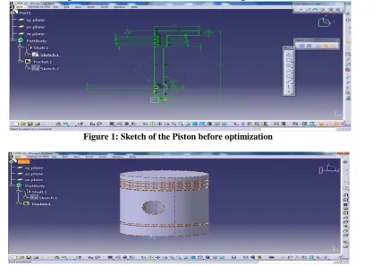
Thus, the dimensions for the piston are calculated and these are used for modelling the piston in CATIA V5 R19. In the above procedure the ribs in the piston are not taken into consideration, so as make the piston model simple in its design. In modelling a piston considering all factors will become tedious process. Thus, a symmetric model is developed using the above dimensions.
Piston was modelled using CATIA V5 R19 software which is shown in Figure 1.
Figure 1: Sketch of the Piston before optimization
Copyright to IJIRSET www.ijirset.com 7838
ISSN: 2319-8753
I
nternational
J
ournal of
I
nnovative
R
esearch in
S
cience,
E
ngineering and
T
echnology
(An ISO 3297: 2007 Certified Organization)
Vol. 2, Issue 12, December 2013
The CAD and FEA of Piston
The design of the piston starts with the definition of the piston geometry using 3D CAD software. This 3D CAD geometric model is then imported to FEA software and analysed under the predicted service conditions before anything is made. That speeds up the design and testing process, reduces the lead time to create new pistons designs, and produces a better product. The idea behind finite analysis is to divide a model piston into a fixed finite number of elements. Computer software generates and predicts the overall stiffness of the entire piston. Analyzing the data it is possible predict how the piston will behave in a real engine and allows the engineer to see where the stresses and temperatures will be the greatest and how the piston will behave [5]. Analysis of the piston is done to optimize the stresses and minimize the weight using ANSYS. The mathematical model of optimization is established firstly, and the FEA is carried out by using the ANSYS software. Based on the analysis of optimal result, the stress concentrates on the piston has become evaluate, which provides a better reference for redesign of piston.
III. MESHING OF PISTON BEFORE OPTIMIZATION
Element used is 20 node Tetrahedron named soilid90 [6]. The element size is taken as 5, then total number elements were 57630 and nodes were 91176 found in meshed model.
Figure 3: Meshed Piston Model
THERMAL AND GEOMETRIC PROPERTIES OF THE PISTON MATERIAL
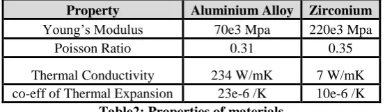
It is important to calculate the piston temperature distribution in order to control the thermal stresses and deformations within acceptable levels.. As much as 60% of the total engine mechanical power lost is generated by piston ring assembly. The piston skirt surface slides on the cylinder bore. A lubricant film fills the clearance between the surfaces. The small values of the clearance increase the frictional losses and the high values increase the secondary motion of the piston. Most of the Internal Combustion (IC) engine pistons are made of an aluminium alloy which has a thermal expansion coefficient, 80% higher than the cylinder bore material made of cast iron. The thermal and geometric properties are as shown in below :
Property Aluminium Alloy Zirconium
Young’s Modulus 70e3 Mpa 220e3 Mpa
Poisson Ratio 0.31 0.35
Thermal Conductivity 234 W/mK 7 W/mK
co-eff of Thermal Expansion 23e-6 /K 10e-6 /K
Copyright to IJIRSET www.ijirset.com 7839
ISSN: 2319-8753
I
nternational
J
ournal of
I
nnovative
R
esearch in
S
cience,
E
ngineering and
T
echnology
(An ISO 3297: 2007 Certified Organization)
Vol. 2, Issue 12, December 2013
APPLYING TEMPERATURES, CONVECTIONS AND LOADS
The piston is divided into the areas defined by a series of grooves for sealing rings. The boundary conditions for mechanical simulation were defined as the pressure acting on the entire piston head surface (maximum pressure in the engine cylinder). It is necessary to load certain data on material that refer to both its mechanical and thermal properties to do the coupled thermo-mechanical calculations. The temperature load is applied on different areas and pressure applied on piston head. The regions like piston head and piston ring regions are applied with large amount of heat (160°C- 200°C). The convection values on the piston wall ranges from
232W/mK to 1570W/mK. and the working pressure is 2Mpa
.
IV. OPTIMIZATION OF PISTON
After generating an accurate finite element model a strategy for the optimization workflow was defined. Target of the optimization was to reach a mass reduction of the piston.
Objective Function: Minimize mass Subject to constraints:
(i) Maximum Vonmisses stress<Allowable or design stress (ii) Manufacturing constraints
(iv) After carrying out static structural analysis the stresses in each loading conditions were studied and then area where excess material can be removed were decided so that maximum vonmisses stress does not exceed allowable and factor of safety is kept above 1.5
(v) Following reasons where scope for material removal
Radial Thickness of the ring
Axial Thickness of the ring
Maximum Thickness of the Barrel
Width of the Top Land
Width of other ring lands
PISTON MODEL AFTER OPTIMAISATION
The meshing of the piston after optimization is done with the same element structure and size i.e., taken before optimization. The total number elements were 78221 and nodes were 47286 found in meshed model.
S No Design 2 -Dimensions Size in mm
1 Length of the Piston(L) 152
2 Cylinder bore/outside diameter of the piston(D) 140
3 Radial thickness of the ring (t1) 3.46
4 Axial thickness of the ring (t2) 3.52
5 Maximum thickness of barell (t3) 9.08
6 Width of the top land (b1) 9.36
7 Width of other ring lands (b2) 3.24
Table3: Design Specification after optimization
Copyright to IJIRSET www.ijirset.com 7840
ISSN: 2319-8753
I
nternational
J
ournal of
I
nnovative
R
esearch in
S
cience,
E
ngineering and
T
echnology
(An ISO 3297: 2007 Certified Organization)
Vol. 2, Issue 12, December 2013
Figure 4: Sketch of the Piston after optimization
Figure 5: Model of the piston
V. ANALYSIS RESULTS AND DISCUSSIONS
Analysis is the process of breaking a complex topic or substance into smaller parts to gain a better understanding of it. The current model is undergone Thermal Analysis and followed by Static Analysis, together called as Coupled Field Analysis. The meshed component is analyzed to find the thermal stresses of the piston.
The component is subjected to the influence of heat conduction at the top of the piston and heat convection to side lands etc. The following images are shown for resulted deformation and vonmisses stresses before and after optimization
1). Deformation and Vonmisses Stress before Optimization
Copyright to IJIRSET www.ijirset.com 7841
ISSN: 2319-8753
I
nternational
J
ournal of
I
nnovative
R
esearch in
S
cience,
E
ngineering and
T
echnology
(An ISO 3297: 2007 Certified Organization)
Vol. 2, Issue 12, December 2013
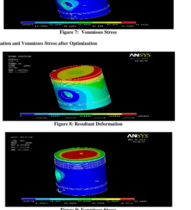
Figure 7: Vonmisses Stress
2). Deformation and Vonmisses Stress after Optimization
Figure 8: Resultant Deformation
Figure 9: Vonmisses Stress
Copyright to IJIRSET www.ijirset.com 7842
ISSN: 2319-8753
I
nternational
J
ournal of
I
nnovative
R
esearch in
S
cience,
E
ngineering and
T
echnology
(An ISO 3297: 2007 Certified Organization)
Vol. 2, Issue 12, December 2013
Figure 10: Comparison of Uncoated Aluminium Alloy Piston and Coated Aluminium Alloy Piston
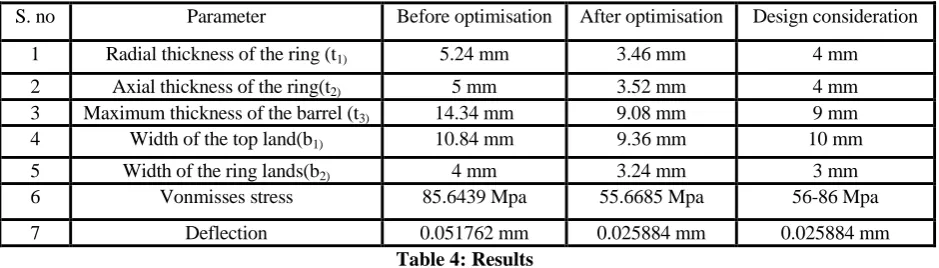
The optimized values after optimization using ANSYS are given in the following Table
S. no Parameter Before optimisation After optimisation Design consideration
1 Radial thickness of the ring (t1) 5.24 mm 3.46 mm 4 mm
2 Axial thickness of the ring(t2) 5 mm 3.52 mm 4 mm
3 Maximum thickness of the barrel (t3) 14.34 mm 9.08 mm 9 mm
4 Width of the top land(b1) 10.84 mm 9.36 mm 10 mm
5 Width of the ring lands(b2) 4 mm 3.24 mm 3 mm
6 Vonmisses stress 85.6439 Mpa 55.6685 Mpa 56-86 Mpa
7 Deflection 0.051762 mm 0.025884 mm 0.025884 mm
Table 4: Results
The length 152 mm and the diameter 140 are assumed to be constant. It is not considerable that the variations in piston length and diameter of the piston. The radial thickness of the piston has affected more as it is very small in size and the temperature and heat flow are very high to this size of thickness. Before optimization value is given as 5.24mm and obtained after optimization is 3.46mm. This is rounded to next highest value i.e., 4mm and is taken into consideration for design. The axial thickness of the piston ring before optimization is 5mm; it is changed to 3.52mm after optimization, since the more and more heat and stress applied through groves as it is very near to the head of the piston. This is rounded to next highest value i.e., 4mm is taken into consideration for design. The maximum thickness of the barrel before optimization is 14.34mm has much affected in variation of size after applying pressure and temperature loads and is changed to 9.08mm and rounded to next highest value i.e., 10mm taken into consideration. The initial value i.e., before optimization is 10.84mm and is changed after applying pressure which is directly applied on the head i.e., top of the piston as a result the shape of the piston on top will become just like a bowl. The value after optimization is obtained as 9.36mm and it is rounded to 10mm. This value is considerable for design. The width of the other lands i.e., near piston rings are 4mm in size and is changed due to pressure and heat applied on rings through groves. The value after optimization is 3.24mm and is rounded to 3mm
.
9 10 11 12 13 14
76 2851 8368 8366
STRE
SS
TOP LAND
Top Land - Vonmises Stress
Uncoated AL Piston
Copyright to IJIRSET www.ijirset.com 7843
ISSN: 2319-8753
I
nternational
J
ournal of
I
nnovative
R
esearch in
S
cience,
E
ngineering and
T
echnology
(An ISO 3297: 2007 Certified Organization)
Vol. 2, Issue 12, December 2013
.VI. CONCLUSIONS
Piston skirt may appear deformation at work, which usually causes crack on the upper end of piston head. Due to the deformation, the greatest stress concentration is caused on the upper end of piston, the situation becomes more serious when the stiffness of the piston is not enough, and the crack generally appeared at the point A which may gradually extend and even cause splitting along the piston vertical. The stress distribution on the piston mainly depends on the deformation of piston. Therefore, in order to reduce the stress concentration, the piston crown should have enough stiffness to reduce the deformation.
1. The optimal mathematical model which includes deformation of piston crown and quality of piston and piston skirt.
2. The FEA is carried out for standard piston model used in diesel engine and the result of analysis indicate that the maximum stress has changed from 85 Mpa. to 55 Mpa. And biggest deformation has been reduced from 0.051762 mm to 0.025884 mm.
FUTURE SCOPE OF THE WORK
Piston Design models are simulated on iteration based and it requires more number of iterations to check whether design is safe or not and to validate the models with the allowable. Instead of the above process, DOE – Design of Experiments concept can be used to optimize the design within short time and to get better optimized parameters. DOE should be carried in Ansys workbench. In Ansys workbench modelling can be done from Catia or Design Modeller using parametric model options. DP stands for design points, optimization can be done in workbench based on the required outputs namely deformations and stress with in prescribed limits
.
ACKNOWLEDGEMENT
The authors sincerely thank Department of Mechanical Engineering, JNTU College of Engineering Hyderabad for support, co-operation and encouragement that enabled this project.
REFERENCES
[1] A.Atish Gawale, A. Shaikh and Vinay Patil, “Nonlinear Static Finite Element Analysis and Optimization of connecting rod World
Journal of Science and Technology, Vol. 2(4), pp .01-04, 2012.
[2] A. R. Bhagat, Y. M. Jibhakate, Thermal Analysis and Optimization of I.C. Engine Piston Using Finite Element Method, International
Journal of Modern EngineeringResearch (IJMER), Vol.2, Issue.4, pp.2919-2921, 2012.
[3] Kamo R., Assanis D.N., Bryzik W.: Thin thermal barrier coatings for engines. SAE Transactions 1989, No 980143.
[4] Ekrem Buyukkaya, “Thermal Analysis of functionally graded coating AlSi alloy and steel pistons”, Surface and coatings technology (2007)
[5] P. Carvalheira1, and P. Gonçalves, FEA of Two Engine Pistons Made of Aluminium Cast Alloy A390 and Ductile Iron 65-45-12 Under
Service Conditions, 5th International Conference on Mechanics and Materials in Design Porto-Portugal, 24- 26, pp .1-21, 2006.
[6] C.H. Li, Piston thermal deformation and friction considerations, SAE Paper, vol. 820086, 1982.
[7] Properties And Selection: Irons, steels and high performance alloy, ASM Handbook, vol. 1, ASM International, 1990.
[8] A.C. Alkidas, Performance and emissions achievements with an uncooled heavy duty, single cylinder diesel engine, SAE, vol. 890141,
1989.
[9] A.C. Alkidas, Experiments with an uncooled single cylinder open chamber diesel, SAE Paper, vol. 870020, 1987.