An Artificial Intelligence Based Grid Tied SPV System with
Adaptive DC Link Voltage for CPI Voltage Variations
Chandra Shravan Kumar.T1
, Mondi.Vinod Kumar
2, R.Suresh Babu
3 1M.Tech Student (EPS), J.B. Institute of Engineering and Technology (UGC Autonomous), Hyderabad. Email: [email protected]
2
Sr. Assistant Professor, Department of EEE, J.B. Institute of Engineering and Technology (UGC Autonomous), Hyderabad.
Email: [email protected]
3
Associate Professor & HOD, Department of EEE, J.B. Institute of Engineering and Technology (UGC Autonomous), Hyderabad. Email: [email protected]
Abstract-- This proposed model deals with a three-phase two-stage grid tied SPV (solar photo-voltaic) system. The first stage is a boost converter, which serves the purpose of MPPT (maximum power point tracking) and feeding the extracted solar energy to the DC link of the PV inverter, whereas the second stage is a two-level VSC (voltage source converter) serving as PV inverter which feeds power from a boost converter into the grid. The aim of this controller is to achieve an optimum MPP operation without the need of atmospheric conditions measurements and to enhance the efficiency of the PV power system. This model also uses an adaptive DC link voltage which is made adaptive by adjusting reference DC link voltage according to CPI (common point of interconnection) voltage. The adaptive DC link voltage control helps in the reduction of switching power losses. A feed forward term for solar contribution is used to improve the dynamic response.
A photovoltaic (PV) system is able to generate wide ranges of voltage and current at terminal output. However, a PV cell is required to functionally maintain a constant direct current (DC) voltage at a desired level during real-time variations . To obtain this goal, a DC/ DC converter together with control scheme topology is used. An adaptive PI control scheme is proposed to stabilize the output voltage of the DC/DC converter, in order to maintain and stabilize the Adaptive DC-link voltage accordingly to the changes of voltage at the Common Point of Interconnection before the grid.
The Point of Common Coupling is a point in the electrical system where multiple customers or multiple electrical loads may be connected. This should be a point which is accessible to both the utility and the customer for direct measurement. Large numbers of small scale solar photovoltaic (PV) systems are being connected to the distribution level of the power grid PV systems are integrated to the power grid via power electronic converters. The model is tested considering realistic grid voltage variations for under voltage variations. This model is advantageous not only in cases of frequent and sustained under voltage (as in the cases of far radial ends of Indian grid) but also in case of normal voltages at CPI. The THD (total harmonics distortion) of grid current has been found well under the limit of an
IEEE-519 standard. The validation of the proposed MPPT controller is shown by MATLAB/SIMULINK simulation.
Keywords: Fuzzy Logic Controller (FLC), Inverters, Sliding Mode Control (SMC), Photovoltaic (PV) systems, Power quality.
1. INTRODUCTION
The electrical energy has a vital role in development of human race in the last century. The diminishing conventional primary sources for electricity production have posed an energy scarcity condition in front of the world. The renewable energy sources such as solar, wind, tidal etc are few of such options which solve the problem of energy scarcity. The cost effectiveness of any technology is prime factor for its commercial success. The SPV (Solar Photovoltaic) systems have been proposed long back but the costs of solar panels have hindered the technology for long time, however the SPV systems are reaching grid parity [1], [2].
The solar energy based systems can be classified into standalone and grid interfaced systems. The energy storage (conventionally batteries) management is the key component of standalone system. Various problems related to battery energy
storage standalone solar energy conversion systems are discussed in [3]–[6].
Considering the problems associated with energy storage systems, the grid interfaced systems are more preferable, in case the grid is present. The grid acts as an energy buffer, and all the generated power can be fed into the grid. Several grid interfaced SPV systems are proposed in past addressing various issues related to islanding, intermittency, modeling etc [7]–[9].
small scale generation from rooftop solar, modularity of power converter and static energy conversion process.
The initial investment in SPV systems is high because of high cost of solar panels [13]. Therefore, considering the initial investments for any installed plant, the aim is to extract maximum energy output from the given capacity. To accomplish the objective of extraction of maximum energy from an installed PV array several techniques are proposed in the literature [14]–[18]. A review of MPPT (Maximum Power Point Tracking) techniques is shown in [14]. An incremental conductance (InC) based MPPT technique is shown in [15]. An ANN based MPPT algorithm is shown in [16]. The application of sliding mode controller to MPPT algorithm is shown in [17]. A combination of fractional open circuit voltage and fuzzy based MPPT technique is shown in [18] wherein a constant offset is added at the output of fuzzy controller to improve the MPPT performance. The incremental conductance based MPPT is fast, accurate and easy to implement. In this paper, a composite InC based MPPT method is used. The composite InC method is a combination of fractional Voc and InC based method. The proposed MPPT technique limits the area of search for MPP point hence improves the MPPT performance.
The tripping of the plant causes generation loss in case of grid tied PV generation system. In general, grid tied VSCs have under voltage and overvoltage protection. The nominal range of set point for under voltage and over voltage is around 0.9 pu and 1.1 pu [19]. This range is very narrow because of reasons such as converter may lose control, increase in converter rating, and converter losses at low voltage etc. In case of weak distribution system, a wide voltage variation is observed. During peak loading condition, a sustained voltage
dip or under voltage is observed commonly. The practical range of voltage variation is about ±15% of the nominal voltage.
Normally in such wide variation of distribution system the shunt connected converter trips frequently. However, in case of tripping of converter the PV generation is lost even when PV power is available. Therefore, minimizing converter trips indirectly increases energy yield from the installed plant. The proposed system is capable of working with wide range of voltage variation hence avoids the generation loss.
The use of two stage SPV generation system has been proposed by several researchers [20]–[23]. Conventionally a DC-DC converter is used as first stage which serves the purpose of MPPT. The duty ratio of DC-DC converter is so adjusted that PV array operates at MPP point. The second stage is a grid tied VSC (Voltage Source Converter) which feeds the power into the distribution system. A single phase two stage grid tied PV generation system with constant DC link voltage is shown in [20]. Moreover, the three phase grid tied PV
generation system with constant DC link voltage control is also shown in [21], [22]. The concept of loss reduction by adaptive DC link voltage for VSC in hybrid filters is shown in [23], [24] wherein, the DC link voltage is adjusted according to reactive power requirement of filter. However, in the proposed system the DC link voltage of VSC is made adaptive with respect to CPI voltage variation.
Moreover, the circuit topologies in both the systems are different. Therefore, the work presented in [23], [24] is very different from the proposed work. For proper control of VSC currents, the DC link voltage reference is set more than peak of three phase line voltages. The limitation for current control in single-phase grid connected converter is shown in [25]. Considering the variation of CPI (Common Point of Interconnection) voltage, the reference DC link voltage is kept above the maximum allowable CPI voltage. Therefore in case of fixed DC link voltage control for VSC, the system always operates at a DC link voltage corresponding to worst case condition.
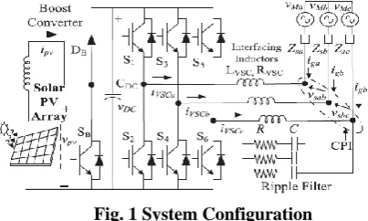
The system configuration for the proposed system is shown in Fig. 1. A two stage system is proposed for grid tied SPV system. The first stage is a DC-DC boost converter serving for MPPT and the second stage is a two-level three phase VSC. The PV array is connected at the input of the boost converter and its input voltage is controlled such that PV array delivers the maximum power at its output terminals. The output of boost converter is connected to DC link of VSC. The DC link voltage of VSC is dynamically adjusted by grid tied VSC on the basis of CPI voltage. The three phase VSC consists of three IGBT legs. The output terminals of VSC are connected to interfacing inductors and the other end of interfacing inductors are connected to CPI. A ripple filter is also connected at CPI to absorb high frequency switching ripples generated by the VSC.
Fig. 1 System Configuration
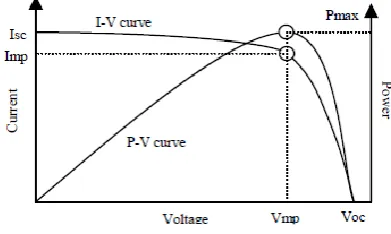
In solar power system the power delivered to the load is highly dependent on solar radiation and PV array temperature. I-V and P-V curves of a solar cell with constant module temperature and solar radiation have been shown in figure 2. At the intersection of Imp and
Fig. 2 Current-voltage and power-voltage characteristics of a solar cell
As per maximum power transfer theorem, the circuit delivers maximum power to the load when source impedance matches the load impedance. In case of stand-alone solar system dc-dc converter is connected in between PV array and the dc load. Maximum power point tracking (MPPT) system varies the duty cycle of the dc-dc converter in order to match source and load impedance and to deliver maximum power to the load. Various MPPT methods have been reported in the literature. These methods can be classified as: i) methods based on load line adjustment of I-V curve and ii) method based on artificial intelligence (fuzzy logic or neural network based MPPT methods). The MPPT methods viz. perturb and observe (P & O), incremental conductance (INC), voltage feedback (VF) are based on load line adjustment of I-V curve. These methods have been found less suitable under uncertainties due to varying atmospheric and load conditions. The MPPT system based on artificial intelligence (fuzzy logic or neural network) has robust capabilities in regard to uncertainties [2, 3].
Real time simulation and comparative analysis of five mostly referred MPP T techniques viz. perturb and observe, incremental conductance, fuzzy logic, neural network and adaptive neuro-fuzzy inference system (ANFIS) based MPPT techniques have been presented in this paper. The paper is organized as follows. In section two a brief introduction of various MPPT techniques has been presented. Section three describes the modeling of solar PV system. Modeling and real time simulation of MPPT algorithms has been given in section four. In section five, comparative analysis of five MPPT techniques and experimentation results have been presented, followed by conclusions.
2. PV CELL MODELLING
The photovoltaic generator is neither voltage nor current sources but can be approximated as current generator with dependent voltage source, where the I-V characteristic can be expressed by the equation 1[7],[8].
The I-V curve is essentially influenced by the variation of two inputs which are the solar insolation and the array temperature. The adaption of the equation (1) to different levels of the solar insolation and temperature can be represented by the following equations [9]:
3. PV ARRAY CHARACTERISTICS
The use of single diode equivalent electric circuit makes it possible to model the characteristics of a PV cell. The mathematical model of a photovoltaic cell can be developed using MATLAB simulink toolbox. The basic equation from the theory of semiconductors that mathematically describes the I-V characteristic of the Ideal photovoltaic cell is given by
I = Ipvcell-Id (1)
Where,
Id = I0cell[exp(qv/αkT)-1] (2) Therefore
I = Ipvcell- I0cell[exp(qv/αkT)-1] (3)
Where, „IPVCell‟ is the current generated by the incident light (it is directly proportional to the Sun irradiation), Id is the diode equation, Io, cell‟ is the reverse saturation or leakage current of the diode, „q‟ is the electron charge [1.60217646* 10−19C], k is the Boltzmann constant [1.3806503 *10−23J/K], „T‟ is the temperature of the p-n
junction, and „a‟ is the diode ideality constant. Fig.3 shows the equivalent circuit of ideal PV cell.
Fig. 3 Equivalent circuit of ideal PV cell
additional parameters (as shown in Fig.8) to the basic equation:
I = Ipv-Io[exp(V+IRs/Vtα)-1]-(V+IRs/Rp) (1)
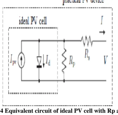
Where Vt = NskT/q is the thermal voltage of the array with „Ns‟ cells are connected in series. Cells connected in parallel increases the current and cells connected in series provide greater output voltages. V and I are the terminal voltage and current. The equivalent circuit of ideal PV cell with the series resistance (Rs) and parallel resistance (Rp) is shown in Fig.8.
Fig. 4 Equivalent circuit of ideal PV cell with Rp and Rs
For a good solar cell, the series resistance (Rs), should be very small and the shunt (parallel) resistance (Rp), should be very large. For commercial solar cells (Rp) is much greater than the forward resistance of a diode. The I-V curve is shown in Fig.5. The curve has three important parameters namely open circuit voltage (Voc), short circuit current (Isc) and maximum power point (MPP). In this model single diode equivalent circuit is considered. The I-V characteristic of the photovoltaic device depends on the internal characteristics of the device and on external influences such as irradiation level and the temperature.
Fig. 5 I-V and P-V characteristics of PV cell
4. BOOST CONVERTER MODEL
As mentioned above, a DC/DC boost converter is placed between the PV array and load stage to vary the output voltage of the PV array to the maximum power point which is calculated by the fuzzy logic or the neural network controller.
From Fig. 6, by considering the steady state operation, the transfer function of the boost converter can be expressed as,
Where, is the duty cycle used by converter control, Vout is the output voltage and VPV is the PV array output voltage.
Fig. 6 Equivalent circuit of a boost converter
The relation between the input and output of the boost converter can be expressed with the help of differential equations obtained by direct application of KCL and KVL to the circuit.
where, IL the is DC/DC output current. 5. FUZZY LOGIC BASED MPPT
Fig. 7 Block diagram of Fuzzy Controller
The two inputs i.e. change of error (CE) and error (E) are defined as,
Where, PPV is the instantaneous power of PV array fuzzy inference is processed using Mamdani‟s method [10]. Defuzzification uses the center of gravity to process output which is the duty cycle [11].
The fuzzy rule base used in this paper [12], is given in Table I as,
TABLE I
FUZZY RULE BASE FOR FLC
MPPT methods based on artificial intelligence have become prevalent in recent years as compared to conventional methods because of good and fast response under rapid variations in temperature and solar radiation. The fuzzy logic based MPPT method does not require the exact model of PV system for its design [5]. In most of the literature, fuzzy logic based MPPT has been proposed with two inputs and one output. The two input variables are error E(k) and change in error ΔE(k), given by:
E(k) = ΔI/ΔV + I/V (3)
ΔE(k) = E(k) – E(k-1) (4)
Where, I is output current from PV array, ΔI is I(k)-I(k-1); V is output voltage from array, ΔV is V(k)-V(k-1).The fuzzy inference can be carried out by one of the various available methods (Mamdani‟s method has been mostly
used) and the defuzzification can be done using centre of gravity method to compute the output (duty cycle). The scheme of such MPPT method has been shown in figure 8.
Fig. 8 Fuzzy logic based scheme for MPP tracking
Sliding Mode Signal Tracking
Normally, SMC is considered as a good alternative to the control of switching converters. The main advantages of such control scheme over classical one are; its robustness, and high dynamics performances under parameter fluctuations. The various steps of this control scheme can be outlined by using the equivalent control concept, as follows [13, 20].The first step is the selection of the switching surface S(x; t) (where x is the system state vector), for the single phase VSI system, so that, it can act as a reference path for the trajectory of the controlled system. It is important to note that for an ideal SMC, it requires an infinite switching frequency, so that, the state trajectories in neighborhood of the switching surface can move precisely along the surface. But operation of such infinite switching in power electronics inverter system is practically impossible. It is therefore necessary a typical control circuit that would require a relay or hysteresis function to restrict the infinite switching frequency as shown in Fig. 2(a). Where the
control signal is defined as
Fig. 9 Schematic diagram showing the: (a) hysteresis function; and (b) the state trajectory in the vicinity of sliding surface S = 0.
The next step is achieving the equivalent control ueq by applying the invariance condition
(6)
6. SIMULATION RESULTS
The shown below simulink model of a three phase two stage grid tied SPV system shows the boost converter which consists of a IGBT , a capacitor and LC element and a diode, as a first stage. And in the second stage, it consists of a three phase inverter which has 6 IGBT‟s.
Fig. 9 Simulink model of two stage grid tied SPV system using MPPT based INC and PI controller
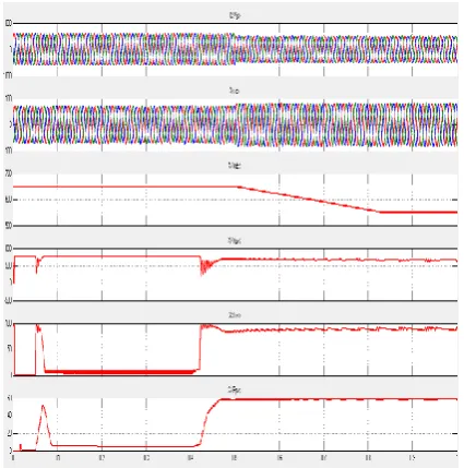
The waveforms show grid voltage and grid current , the adaptive D.C voltage and voltage and current waveforms of PV panel up to 15% voltage variations at CPI while using INC with MPP technique at Boost Converter.
Fig. 10 Simulated performance for, (a) variations in the grid voltage, (b) variations the grid current, (c) adaptive DC voltage waveform as the voltages variations range upto 15% at CPI, (d),(e),(f) shows the voltage ,current and power waveforms of PV panel
The simulink model of a three phase two stage grid tied SPV system shows the boost converter which consists of a IGBT , a capacitor and LC element and a diode, as a first stage. And in the second stage , it consists of a three phase inverter which has 6 IGBT‟s.
Fig . 11 Simulink diagram of a two stage grid tied SPV system employing FLC and SMC control approaches
The waveforms show grid voltage and grid current, the adaptive D.C voltage and voltage and current waveforms of PV panel upto 20% voltage variations at CPI while employing FLC with MPP technique at Boost Converter and SMC at Inverter.
Fig. 12 Simulated performance for, (a) variations in the grid voltage, (b) variations the grid current, (c) adaptive DC voltage waveform as the voltages variations range upto 20% at CPI, (d),(e),(f) shows the
voltage ,current and power waveforms of PV panel
controller with Inverter is 3.92%.
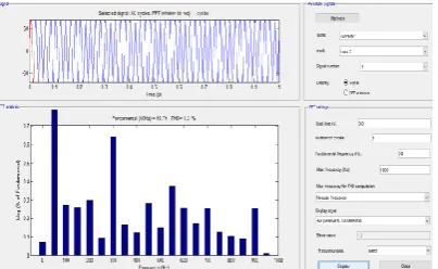
Fig. 13 Total Harmonic Distortion of the grid currents when the range of the variations at the CPI is 15%
The Total Harmonic Distortion of the grid currents at the grid when Fuzzy Logic control is used with Boost Converter and Sliding Mode Control is employed with Inverter is noted to be 0.98%.
Fig. 14 Total Harmonic Distortion of the grid currents when the range of the variations at the CPI is 20%
7. CONCLUSION
A two-stage system has been proposed for three-phase grid connected solar PV generation. Earlier, works have been done in this area using Incremental based MPP Technique to control the boost converter and adaptive DC link voltage control approach for control of grid tied VSC.
In this proposed model, a Fuzzy Logic based MPPT algorithm is used for control of the boost converter and Sliding Mode control approach has been proposed for control of grid tied VSC.. The performance of the system has been demonstrated for wide range of CPI voltage variation. The DC link voltage is made adaptive with respect to CPI voltage which helps in reduction of losses in the system. The fuzzy logic and sliding mode control approaches not only enchances the speed and accuracy of the model , but also improves performance of the system upto 20 % of CPI variations.
A PV array feed forward term is used which helps in fast dynamic response. The concept of adaptive DC link voltage has been proposed for grid tied VSC for PV application however, the same concept can be
extended for all shunt connected grid interfaced devices such as, STATCOM, D-STATCOM etc. The proposed model yields increased energy output using the same hardware resources just by virtue of difference in DC link voltage control structure. The THD of the grid currents is observed to be 1.21% which has improved quite a lot from the earlier works (within IEEE-519 standard). The Fuzzy Logic and Sliding Mode Control used in this model not only increased the speed of the system but also improved its accuracy. We can further improve the system by using other artificial intelligence techniques. The same can be implemented for more variations at CPI.
Control Employe d
CPI Variations
Vg Ig Vd c
THD
INC & PI 15% 345 115 550 3.92%
FLC & SMC
20% 330 120 520 0.98%
REFERENCES
[[1] M. Pavan and V. Lughi, “Grid parity in the Italian commercial and industrial electricity market,” in Proc. Int. Conf. Clean Elect. Power (ICCEP‟13), 2013, pp. 332–335.
[2] M. Delfanti, V. Olivieri, B. Erkut, and G. A. Turturro, “Reaching PV grid parity: LCOE analysis for the Italian framework,” in Proc. 22nd Int. Conf.
Exhib. Elect. Distrib. (CIRED‟13), 2013, pp. 1–4. [3] H.Wang and D. Zhang, “The stand-alone PV generation system with parallel battery charger,” in Proc. Int. Conf. Elect. Control Eng. (ICECE‟10), 2010, pp. 4450–4453.
[4] M. Kolhe, “Techno-economic optimum sizing of a stand-alone solar photovoltaic system,” IEEE Trans. Energy Convers., vol. 24, no. 2, pp. 511–519, Jun. 2009. [5] D. Debnath and K. Chatterjee, “A two stage solar photovoltaic based stand alone scheme having battery as energy storage element for rural deployment,” IEEE Trans. Ind. Electron., vol. 62, no. 7, pp. 4148–4157, Jul. 2015.
[6] S. Krithiga and N. G. Ammasai Gounden, “Power electronic configuration for the operation of PV system in combined grid-connected and stand-alone modes,” IET Power Electron., vol. 7, no. 3, pp. 640–647, 2014. [7] I. J. Balaguer-Álvarez and E. I. Ortiz-Rivera, “Survey of distributed generation islanding detection methods,” IEEE Latin Amer. Trans., vol. 8, no. 5, pp. 565–570, Sep. 2010.
simulating photovoltaic power systems,” IEEE J. Photovoltaics, vol. 3, no. 1, pp. 500–508, Jan. 2013. [10] P. Chiradeja, “Benefit of distributed generation: A line loss reduction analysis,” in Proc. IEEE/PES Transmiss. Distrib. Conf. Exhib.: Asia Pac., 2005, pp. 1– 5.
[11] A. Yadav and L. Srivastava, “Optimal placement of distributed generation: An overview and key issues,” in Proc. Int. Conf. Power Signals Control Comput. (EPSCICON‟14), 2014, pp. 1–6.
[12] K. A. Joshi and N. M. Pindoriya, “Impact investigation of rooftop Solar PV system: A case study in India,” in Proc. 3rd IEEE PES Int. Conf. Exhib. Innovative Smart Grid Technol. (ISGT Europe), 2012, pp. 1–8.
[13] E. Drury, T. Jenkin, D. Jordan, and R. Margolis, “Photovoltaic investment risk and uncertainty for residential customers,” IEEE J. Photovoltaics, vol. 4, no. 1, pp. 278–284, Jan. 2014.
[14] B. Subudhi and R. Pradhan, “A comparative study on maximum power point tracking techniques for photovoltaic power systems,” IEEE Trans. Sustain. Energy, vol. 4, no. 1, pp. 89–98, Jan. 2013.
[15] F. Liu, S. Duan, F. Liu, B. Liu, and Y. Kang, “A variable step size INC MPPT method for PV systems,”
IEEE Trans. Ind. Electron., vol. 55, no. 7, pp. 2622– 2628, Jul. 2008.
[16] M. Farhat, A. Flah, and L. Sbita, “Photovoltaic maximum power point tracking based on ANN control,”
Int. Rev. Model. Simul., vol. 7, no. 3, pp. 474–480, 2014. [17] J. Ghazanfari and M. M. Farsangi, “Maximum power point tracking using sliding mode control for photovoltaic array,” Iran. J. Elect. Electron. Eng., vol. 9, no. 3, pp. 189–196, 2013.
[18] M. Adly, H. El-Sherif, and M. Ibrahim, “Maximum power point tracker for a PV cell using a fuzzy agent adapted by the fractional open circuit
voltage technique,” in Proc. IEEE Int. Conf. Fuzzy Syst. (FUZZ’11), 2011, pp. 1918–1922.
[19] M. E. Ropp, J. G. Cleary, and B. Enayati, “High penetration and antiislanding analysis of multi-single phase inverters in an apartment complex,” in Proc. IEEE Conf. Innovative Technol. Efficient Reliab. Electr. Supply (CITRES’10), 2010, pp. 102–109.
[20] S. Deo, C. Jain, and B. Singh “A PLL-Less scheme for single-phase grid interfaced load compensating solar PV generation system,” IEEE Trans. Ind. Informat., vol. 11, no. 3, pp. 692–699, Jun. 2015.
[21] B. Singh, D. T. Shahani, and A. K. Verma, “Neural network controlled grid interfaced solar photovoltaic power generation,” IET Power Electron., vol. 7, no. 3, pp. 614–626, Jul. 2013.
[22] C. Jain and B. Singh “A frequency shifter based simple control for multifunctional solar PV grid interfaced system,” in Proc. 37th Nat. Syst. Conf., 2013, pp. 363–374.
[23] C.-S. Lam,W.-H. Choi, M.-C.Wong, and Y.-D. Han, “Adaptive DC-Link voltage-controlled hybrid active
power filters for reactive power compensation,” IEEE Trans. Power Electron., vol. 27, no. 4, pp. 1758–1772, Apr. 2012.
[24] C.-S. Lam, M.-C. Wong, W.-H. Choi, X.-X. Cui, H.-M. Mei, and J.-Z. Liu, “Design and performance of an adaptive low-DC-voltage controlled LC-hybrid active power filter with a neutral inductor in three phase four-wire power systems,” IEEE Trans. Ind. Electron., vol. 61, no. 6, pp. 2635–2647, Jun. 2014.
[25] Y.-M. Chen, H.-C. Wu, Y.-C. Chen, K.-Y. Lee, and S.-S. Shyu, “The AC line current regulation strategy for the grid-connected PV system,” IEEE Trans. Power Electron., vol. 25, no. 1, pp. 209–218, Jan. 2010.
Mr. Chandra Shravan Kumar.T currently pursuing M.Tech in Electrical Power Systems from J.B. Institute of Engineering and Technology (UGC Autonomous), Affiliated to JNTU Hyderabad, India. He received B.Tech Degree in Electrical and Electronics Engineering from St Mary's College of Engineering and Technology affiliated to JNTUH in the year 2007. He is interested in the field of Electrical Power Systems and Solar Energy Systems.
Email: [email protected]
Mr. Mondi. Vinod Kumar received the Master of Technology degree in Electrical Power systems from J. B. Institute of Engineering and Technology, Affiliated to JNTU Hyderabad, in 2008. He received B.Tech degree in Electrical & Electronics Engineering from Vidya Jyothi Institute of Technology affiliated to JNTU Hyderabad in 2004. He is currently working as a Sr. Assistant Professor at J.B. Institute of Engineering and Technology (UGC Autonomous), Affiliated to JNTU Hyderabad, India. His areas of interest include power system.
Email: [email protected]
Mr. R. Suresh Babu received the Master of Technology Degree in High Voltage Engineering from JNTU Kakinada. He received the Bachelor of Engineering degree in Electrical and Electronics Engineering from VR Siddhartha Engineering College from Nagarjuna University. He is currently working as Associate Professor and Head of the EEE Department in J.B. Institute of Engineering and Technology (UGC Autonomous), Hyderabad, India. He is interested in the field of Power Systems, Electrical Machines and Networking.
Email: [email protected]