Available online: http://edupediapublications.org/journals/index.php/IJR/ P a g e | 994
Powe r Factor Correction of Three-Phase PWM AC Chopper Fed
Induction Motor Drive System Using HBCC Technique
Gorantla Yuva Kishore1, R.Venkata Dileep2, Dr. A.Mallikarjuna Prasad3
1
P.G. Scholar, 2Guide, Assistant Professor, 3Head of the Department 1,2,3
BRANCH : EEE 1,2,3
Geethanjali College Of Engineering And Technology
Email.Id : [email protected], [email protected]
ABS TRACT
In this paper, a new control strategy for an induction motor (IM ) drive system fed from three- phase pulse width modulation (PWM ) AC chopper is proposed. The main objective of the proposed control scheme is to achieve input power factor correction (PFC) of the IM drive system under different operating conditions. PFC is achieved by continuously forcing the actual three-phase supply currents with the corresponding reference currents, which are generated in phase with the supply voltages, using hysteresis band current control (HBCC) technique. The proposed control strategy has two loops; inner and outer loop. Output of the outer loop is the magnitude of the supply reference current resulting from either speed controller or startup controller, whereas output of the inner loop is PWM signals of the AC chopper. The proposed AC chopper features a smaller number of active semiconductor switches; four IGBTs, with only two PWM gate signals. As a result, the proposed system is simple, reliable, highly efficient and cost-effective. M athematical analysis of the drive system is presented. Components of the input LC filter are designed us ing frequency response. The IM drive system is modeled using M ATLAB/SIM ULINK and a laboratory prototype was built and tested. Simulation and experimental results confirm validity and robustness of the proposed control strategy.
Keywords: Choppers (circuits), Pulse width modulation, Voltage control, Insulated gate bipolar transistors, Velocity control, S witches, Induction motors
INTRODUCTION
AC voltage regulators, also called as AC voltage controllers, are used in various applications that require a regulated AC voltage. Lighting control using dimmer circuits, domestic and industrial heating, speed control and soft starters for the induction motors are examples of such applications [1], [2]. Different topologies with different control methods of these regulators in single phase applications and also in three phase applications are presented. The purpose of AC voltage controller is to vary the root mean square (RM S) value of its output that applied to the load circuit. There are three control methods are offered to achieve this objective; ON/OFF method, phase angle (PA) method and pulse width modulation (PWM ) method. All three control methods can be implemented in both single-phase and three-phase applications.
Available online: http://edupediapublications.org/journals/index.php/IJR/ P a g e | 995 occurred for a few integral cycles and
disconnection for the next few cycles of the feeding voltage. Adjusting the number of conducted and interrupted cycles controls the RM S magnitude of the output voltage. In ON/OFF method, the generated harmonics by the switching actions are reduced as silicon-controlled rectifiers (SCRs) are switched ON at zero voltage and switched OFF at zero current. However, undesirable sub-harmonic components may be produced [3]. Applications of this method is restricted to heating and temperature control systems due to the discontinuity of the power source at low demand levels.
In PA control method, the output of the AC voltage controller is regulated by adjusting the firing angles of SCRs. The power circuit of a single-phase regulator with PA control method is generally consisted of two thy ristors which are joined back to back between the AC source and the load circuit, while three-phase regulator is composed of three pairs of SCRs. In [4], [5], soft starting for induction motor (IM ) fed from a thyristorized voltage regulator is presented. The artificial techniques are utilized to adjust the motor voltage by varying the firing angles of the thyristors at certain operating instant of speed and torque commands. In [6], a voltage ramp technique is presented for starting of an AC motor. The voltage, in ramp technique, is increased gradually by adjusting the SCRs firing angles during starting of the motor. In [7], [8], a closed loop current control approach that determines the firing angles of thyristors required to keep the motor current at starting instant within a limit value is presented. In these approaches, a smooth start-up of the IM is obtained. However, numerous sensors and zero crossing detection (ZCD) circuits are required which make these controllers are
complicated and expensive. In addition, the thyristorized AC voltage controller provides significant harmonics and low input power factor (PF) even if the load is a pure
resistive. Recent developments in
semiconductor switches make it possible to
replace SCRs by modern power
semiconductor switches like M OSFETs and IGBTs. Using PWM control method with the modern power switches, the AC voltage regulators performance can be enhanced in terms of harmonics, filter size, input PF and voltage control range [9], [10], [11]. In [12], a speed control of two-phase IM fed from single phase PWM AC chopper is presented. The chopper has power circuit that consists of four IGBT switches. The RM S value of the motor voltage is controlled by changing the duty ratio of the chopper IGBTs and hence the motor speed is adjusted. This chopper is working in buck mode. Buck and boost modes are presented in [13]. Performance of single phase PWM AC chopper can be further improved using voltage harmonic elimination techniques.
Available online: http://edupediapublications.org/journals/index.php/IJR/ P a g e | 996 Different topologies of three phase PWM
AC chopper in different applications are presented in [20], [21], [22], [23]. A three phase PWM AC chopper, has eight IGBTs, feeds an IM is presented in [24]. A configuration of the three-phase chopper with six IGBTs for soft starting of three phase IM is presented in [25], while a four-IGBT configuration is presented in [26]. However, these configurations have low PF. A method of determining the operating PF of the three-phase IM using only the measured current and the manufacturer data of the motor is presented in [27]. In [28], a new asymmetrical pulse width modulated (APWM ) controller for AC chopper fed three-phase IM drive is proposed. In [29], a hysteresis band current control (HBCC) approach is used to control the switching of the three-phase chopper fed three phase AC load. Using HBCC technique, balanced three phase sinusoidal currents are obtained. However, the power circuit of this system uses six IGBTs with six gate pulses which make the
system complex and expensive.
Furthermore, the input PF of this approach is low.
Although researchers focused on PFC of single-phase PWM AC choppers, they have been given a little attention of PFC of three-phase choppers. PFC is important in order to comply with the necessaries of the international standards [30], [31]. On the other side, the reduction in the amount of semiconductor devices and introducing new control strategies are essential for control simplicity, reliability, higher efficiency and lower cost.
In this article, new control strategy for PFC of three phase PWM AC chopper using HBCC technique fed three phase squirrel cage IM with soft starting and speed control operating modes is proposed. The power circuit of the proposed control strategy is
simple, reliable, high efficiency and low cost as it has reduced number of power semiconductor switches. The three phase PWM AC chopper consists of four IGBTs. A new closed-loop control strategy, that uses only two gate pulses to drive the four IGBTs, is achieved. The proposed control strategy has three main control objectives: soft starting, speed control and input PFC, which are achieved by adjusting the RM S value of the input voltage fed the IM terminals. The proposed control strategy is investigated, analysed and simulation results are obtained under different testing conditions. A laboratory prototype model is implemented based on the proposed control strategy. The experimental setup consists of a 1.5 HP squirrel cage IM coupled mechanically with a DC generator for loading purpose, a four- switch PWM AC chopper and a DSP DS-1104 control board. The experimental waveforms are obtained and compared with corresponding simulation waveforms. The rest of the article is organized as: first, description and operating modes of the proposed control strategy is discussed. Then, mathematical analysis of the proposed control strategy is introduced. Finally, the simulation and laboratory waveforms are collected and the article findings are concluded.
S YS TEM DES CRIPTION AND OPERATION PRINCIPLE
Available online: http://edupediapublications.org/journals/index.php/IJR/ P a g e | 997 utilized to continuously connect and
disconnect the motor to and from the AC supply, respectively. Hence, they regulate the delivered power to the motor. While the parallel-connected switch (S4) offers a freewheeling way for discharging the energy kept in the motor windings when the series-connected switches are turned OFF. As series and parallel devices operate in a complementary way, a dead time is introduced to avoid the commutation problems. There are three operating stages: active, freewheeling and dead time. In dead time period, all four devices are turned OFF. The currents paths of the proposed PWM AC chopper fed IM in its three operating stages are illustrated by Fig. 2. A three phase ∆-connected snubber circuit, which has a resistance Rsn and a capacitance Csn per phase, is used to minimize high voltage spikes at IM terminals due to switching of the chopper as well as providing the current path of IM during the dead time period. The input filter is composed of three inductors (whose resistance is Rf and inductance is Lf per phase) and Y-connected three capacitors (whose capacitance Cf per phase). The LC input filter is used with the proposed PFC technique in order to reduce the harmonics of the supply current due to switching of the chopper. The proposed control circuit only generates two PWM complementary gate pulses (g1 and g2) which are used to drive the chopper IGBTs in order to provide the three main tasks of the proposed control strategy.
FIGURE 1. Power circuit o f the proposed three-phase PWM AC chopper fed an IM drive system
Induction Motor
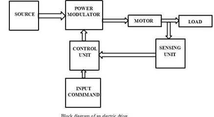
M otion control is required everywhere, be it domestic application or industry. The systems that are engaged for this purpose are called drives. Such a system, if uses electric motors for control is known as an electrical drive. In electrical drives, various
sensors and control algorithms are
employed to control the speed of the motor using suitable speed control methods. The basic block diagram of an electrical drive is shown below:
PROPOS ED CONTROL S TRATEGY
Available online: http://edupediapublications.org/journals/index.php/IJR/ P a g e | 998 track their command current signals to
achieve input PFC, whereas the outer control loop determines the magnitude of the reference currents either from starting mode or speed control mode. As a result, the inner loop controls the phase and the outer loop controls the magnitude of the chopper currents. In the first, the soft starting mode is working, and by giving a switching pulse to the selector switch, the speed control mode is activated and the soft starting mode is turned off.
A. SOFT STARTING MODE
The role of the soft starting mode is to generate the reference value of the supply current in a manner that limits the starting current of the IM at a preset value. The actual current of IM (Im) is measured and its RM S value is evaluated by RM S detector. The command or preset value of the motor current (Im*) and its actual value (Im) are compared. The comparison resulted error is passed into a proportional integral (PI) *). controller to generate the command motor current (Is ) Limiting the starting current provides a smooth acceleration and reduces the torque pulsations of IM during soft starting period.
B. SPEED CONTROL M ODE
There are several methods for controlling the speed of three- phase IM s. These methods can be classified into two main categories according to the control side of the IM : a) speed control methods through the stator such as changing the applied frequency, changing the applied voltage, changing the number of the stator poles and voltage/frequency (v/f) control, and b) speed control methods through the rotor such as rotor resistance control and rotor slip power recovery. Variable frequency drives (VFDs) are the commercial drives. Speed control by VFDs
is based on changing both the stator voltage and frequency of the IM . VFDs are widely used for wide-range variable-speed IM applications. However, they are very expensive and hence not convenient when they are used for limited-range variable-speed IM applications. Since the proposed speed control strategy depends on changing the stator voltage only, so it is simple, low cost and more convenient for limited-range variable-speed IM application which is intended in this research. The role of the speed control mode is to generate the reference current value (Is*) in a way that makes the measured
speed of IM (ωm) follows the *).
Command and measured speed are
command speed (ωm compared and the
difference is used as an input signal to a PI *. speed controller to generate Is.
C. PFC CONTROL
Available online: http://edupediapublications.org/journals/index.php/IJR/ P a g e | 999 of the stator current (Is*) is utilized to
obtain the three phase reference supply currents (isa * ) by multiplying the value (Is*) by unit vectors of the supply voltages (usa, usb and usc) as:
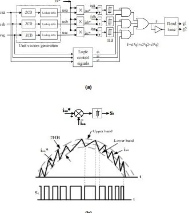
The unit vectors (usa, usb and usc) are generated by measuring the phase voltages of the supply (vsa, vsb and vsc) and by using three zero crossing detection (ZCD) circuits and three lookup tables as shown in Fig. 4a. The reference currents of the supply
(isa *), are compared with their
corresponding actual values (isa, isb and isc) respectively. The resulted errors are passed through three hysteresis bands (HBs) and their outputs are the three switching signals (S1, S2 and S3). Operation of HBCC technique to obtain the switching signal (S1) is explained by Fig. 4b. The logic control signals block is utilized to find the higher value of the supply phase voltages. The switching signal F is generated from the three switching signals (S1, S2 and S3) and the three logic control signals (q1, q2 and q3) as:
x
FIGURE 2. The currents paths of the proposed PWM AC chopper fed IM . (a)
Active stage. (b) Dead time stage. (c) Freewheeling stage.
The switching signal F and its complementary signal are passed through a dead time block in order to obtain the two PWM complementary signals (g1 and g2) that are used to drive the chopper IGBTs.
The idea of the proposed PFC technique is to force continuously the actual supply currents to follows their corresponding
command currents which are in phase with supply voltages in both the two control modes. Considering a sinusoidal supply voltage, the PF at which a converter system operates is defined as follows:
where Is and Is1 are the RM S values of the supply current and its first order component, respectively. DPF is the displacement power factor that equals the cosine of the angle by which the first order component of the current is displaced with respect to the input voltage wave.
FIGURE 3. Block diagram of the proposed control circuit.
Available online: http://edupediapublications.org/journals/index.php/IJR/ P a g e | 1000 technique, (b) Generation of switching
signal S1.
However, IS1/IS (i.e. the distortion factor) is the ratio of the RM S value of the first order component to the RM S value the supply current Is; which can be calculated as follows:
From (4), the RM S value of the distortion component can be written as:
However, the percentage total harmonics distortion (THD) is defined as:
From (3), (4) and (6), the PF can be written as:
Thus, the DPF should be high and the THD should be low to yield a higher input PF. These factors (DPF and THD) are
controlled using the proposed PFC control.
MATHEM ATICAL ANALYSIS
The mathematical analysis of the proposed AC chopper, LC input filter, and the three-phase squirrel-cage IM are discussed in the following subsections.
A. ANALYSIS of THE PROPOSED
AC CHOPPER
The three-phase supply voltages can be defined as:
where Vm is the peak value of the supply voltage and its angular frequency
is . The supply voltages are chopped by the power regulating switches (S1, S2 and S3). Variation of the duty ratio for IGBT switches of the AC chopper is utilized to change the effective values of the voltage and hence the current of IM . Increasing the duty ratio will allow the value of the input voltage to increase. While reducing the duty ratio reduces the value of the input voltage. The IM input voltage is calculated using the following equation:
where the duty ratio is D. Equation (9) illustrates that the IM voltage is mainly depending on the duty ratio of the PWM AC chopper. The duty ratio can be given by:
where Ton is the on time, Toff is the off time and Tsw is the switching time period. The switching frequency (Fsw) is given by:
In the active stage, the power semiconductor devices (S1, S2 and S3) are ON and the power device S4 is OFF. Therefore, the following equations can be derived:
where vma, vmb, vmc are the three phase motor voltages, and the input voltages to the AC chopper are vca, vcb, vcc. In the freewheeling stage, the power switch S4 is ON and the regulating power switches are OFF. The voltages on the IM terminals are zero as a result we can write
Available online: http://edupediapublications.org/journals/index.php/IJR/ P a g e | 1001
B. ANALYSIS OF THE LC INPUT
FILTER
The theoretical analyses of the LC input filter are described using the following equations as in [26]:
where iSa, iSb, iSc are the supply line currents; Rf is the input filter resistance, Lf is the inductance of input filter and Cf is the capacitance of the input filter; p is the differentiation operator. The filter capacitors currents are ifa, ifb, ifc; and the chopper line currents are ica, icb, icc. The variation of the supply currents (isa, isb, isc) is evaluated by the input filter and the IM parameters.
Since the proposed topology depends on the capacitance of the LC filter, so analysis of the capacitance ripple current is essential. In order to study the ripple current of the capacitance, the filter current (ifa) for phase a can be separated into two components; average component (̅ ) and ripple component (̃ ) as follow:
The rms value of the ripple component of the filter capacitance current ( ) phase a can be derived approximately as follows [32]:
where Ioca is the rms value of phase a chopper output current. Parameters design of the LC input filter depends on its cut-off frequency (Fc) that can be given as:
Proper selection of the cut-off frequency will properly filter out the input pulsating current resulting from the chopper switching. The cut-off frequency should fulfil the following relation:
where Fs and Fsw are the supply and the switching frequencies, respectively. The cut-off frequency (Fc) should be selected 10- 20 times lower than the switching frequency (Fsw) of the PWM AC chopper in order to suppress effectively the high-order harmonics of the input current and, at the same time, higher than the fundamental frequency of the supply; i.e. 60 Hz. Since the average switching frequency of the chopper is 10 KHz as seen in Fig. 5a, the parameters of LC filter have been taken as : Lf= 6 mH, Rf = 0.5 Ω, and Cf= 7 µF,
and hence the cut-off frequency of the LC input filter is equal to 776.6 Hz; about 13 times lower than the switching frequency. The frequency response of the designed low-pass second-order LC input filter is seen in Fig. 5b.
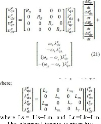
IM MODEL
Available online: http://edupediapublications.org/journals/index.php/IJR/ P a g e | 1002
where Ls = Lls+Lm, and Lr =Llr+Lm. The electrical torque is given by;
The motion equation can be given as :
FIGURE 5. (a) Switching frequency, (b) Frequency response of the LC input filter.
HARDWARE IMPLEMENTATION
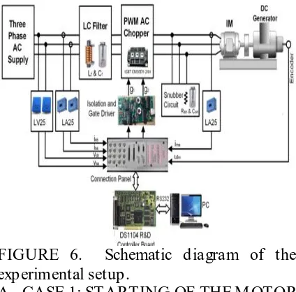
To validate and verify the simulations of the proposed control strategy, a laboratory system of the proposed control strategy was implemented and runs under different operating states. Fig. 6 shows the schematic diagram of the laboratory system, including an input filter, AC chopper, snubber circuit, three phase IM coupled with DC generate as a load, a digital signal
processing control board dSPACE
(DS1104) and IGBT gate driver. AC chopper switches S1, S2, S3 and S4 are 50A/1200V IGBT M ITSUBISHI M odule (CM 50DY-24H). The required pulses (g1 and g2) are generated by using a digital signal processing control board (DS1104) Synchronized with MATLAB/SIM ULINK environment. A gate interface board circuit is connected between the outputs of digital signal control board (D S1104) and the IGBTs to obtain pulses of nearly 15 V to enforce effective IGBT switching states. The three phase supply voltages (VSa,b,c), three phase supply currents (iSa,b,c) and motor phase current (ima) are measured using voltage and current sensors and sent their signals to the digital signal control board (D S1104) through the analogue to digital converter ports. The IM speed (ωm) is measured by position
encoder (HENGSTLER) connected to rotor shaft of IM . The DSP-DS1104 control board has facilitates to capture the experimental data and export them numerically per sample. The DSP-DS1104 board can record the experimental waveforms as capture images or M ATLAB files (.mat). Since the captured images have a low resolution, so the experimental waveforms are plotted with M ATLAB program to obtain figures with a high resolution.
RES ULTS
Available online: http://edupediapublications.org/journals/index.php/IJR/ P a g e | 1003 proposed control strategy theoretically.
While the experimental prototype has been constructed to confirm the proposed strategy experimentally. Three test cases are examined. Corresponding simulation and experimental results are obtained and compared. Parameters of the system under study are given in the appendix.
FIGURE 6. Schematic diagram of the experimental setup.
A. CASE 1: STARTING OF THE M OTOR
In this test case, the motor is started with the proposed control strategy (soft starting mode) at load torque (TL) equal to 25% of the rated torque (TL= 1.75 N.m), and Im * = 7.5A which is 2 times of the rated motor current. Fig. 7 illustrates the motor speed
(ωm), motor phase-a current (ima), and RM S motor phase-a voltage (Vma) responses during starting, respectively. As seen, the rise of the motor phase voltage is controlled during the starting period in order to restrict the starting current at the predetermined level; 2 times of the rated current. Furthermore, the motor speed has a smooth acceleration. So, soft startup of the motor is achieved avoiding the electrical and mechanical drawbacks of the direct online (DOL) starting and hence the motor life is increased.
Fig. 8 illustrates the instantaneous waveforms of the chopped motor voltage (vma), motor current (ima), supply voltage (vsa), and supply current (isa) during startup of the IM . As seen from the results, the motor current lags the motor voltage due to the inductance of the IM windings. Whereas, by the help of the proposed HBCC technique, the supply current (isa) is forced to be in phase with the supply voltage (vsa) regardless the inductive load type of IM making the input PF of the drive system to be approximately unity.
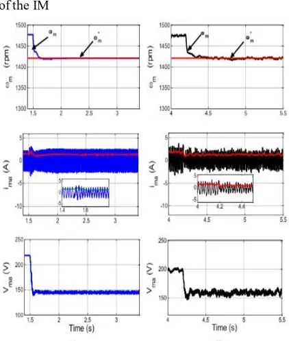
B. CASE 2: ACTIVATION THE SPEED CONTROLLER
Fig. 9 shows the motor speed, current and phase voltage responses when the speed control mode is launched. This mode is activated in simulation at time
t= 1.5 s with speed reference (ω m) load
torque (1.75 N.m). It is clear from the illustrated waveforms in Fig. 9 that the motor speed effectively tracks its reference value. Also, the motor voltage and hence the current decreases with decreasing the motor speed. The experimental results are similar to simulation results and verify the
validation of the proposed control
algorithm.
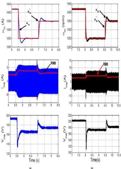
C. CASE 3: STEP CHANGE IN THE MOTOR LOAD TORQUE
Variation of the motor speed, current and phase voltage at step change in the load torque from 25% (1.75 N.m) to 80% (5.6 N.m) of rated load torque are illustrated in Fig. 10. As seen from the waveforms, the motor current and voltage increase with increasing the load torque. Also, the motor speed decreases with increasing the load torque and returns back quickly to its
command value which proves the
Available online: http://edupediapublications.org/journals/index.php/IJR/ P a g e | 1004
A. CASE 4: STEP CHANGE IN THE
REFERENCE SPEED
Fig. 11 shows the motor speed, current and phase voltage responses at step change of the reference speed. In this case, at 80% full load torque, the system is subjected to a step decrease of the reference speed from 1420 rpm to 1250 rpm followed by a step increase in the reference speed from 1250 rpm to 1350 rpm as shown in Fig. 11a. It is clear from the results that the speed controller is robust and effective as
the actual motor speed (ωm) tracks the variations in the reference speed (ωm)
quickly with a minimum steady state error.
Fig. 12 shows the simulation and
experimental results of the reference and measured currents of the supply. It is clear that the measured current follows the reference current in a certain band. This proves the effectiveness of the proposed HBCC strategy.
FIGURE 7. Starting of the motor with the proposed PWM AC chopper. (a) Simulation. (b) Experimental
FIGURE 8. PFC of the d rive system du ring start -up of the IM
Available online: http://edupediapublications.org/journals/index.php/IJR/ P a g e | 1005 FIGURE 10. Variation o f the motor speed, current
and phas e voltag e at step change in the load to rque. (a) Simulation. (b) Experimental.
FIGURE 11. Variation o f the motor speed, current and phase voltage at step chang e in the reference speed. (a) Simulation. (b) Experimental.
FIGURE 12. Reference and measured currents of th e supply. (a) Simulation. (b) Experimental.
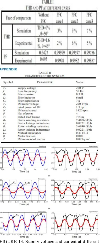
The simulated and experimented waveforms of vsa and isa for the first three testing cases; case 1, case 2 and case 3, are presented in Fig. 13. As illustrated, the simulated and experimental results are in a close agreement, the supply currents are approximately sinusoidal and are in phase with the corresponding supply voltages during all the test cases which ensure that the input PFC is achieved and hence prove the validity of the proposed current control strategy. The drawback of the proposed PWM AC chopper fed IM is that it is one quadrant converter. Therefore, it has not the ability to reverse the speed direction of the motor nor to handle with the negative load torque.
A. THD AND PF COMPARISON
Available online: http://edupediapublications.org/journals/index.php/IJR/ P a g e | 1006 simulation and experiments, the PF for case
1 has 0.99999 and 0.99955 respectively, also the PF for case 2 has 0.99597 and 0.9982 respectively, while the PF for case 3 has 0.99756
FIGURE 13. Supply voltage and current at different testing cases of the proposed system. (a) Case 1. (b)
Case 2. (c) Case 3.
CONCLUS ION
A new control strategy of three-phase squirrel cage IM fed from PWM AC
chopper has been simulated and laboratory implemented using dSPACE (DS1104) control board. The main control objective is to correct the input PF with different operating conditions of the induction motor drive system. Input PFC is achieved by forcing the actual currents of the chopper to track their reference currents that are in phase with the input voltages using HBCC technique. The proposed control strategy uses only two PWM signals for driving the active switches of the AC chopper. The proposed system is simple, reliable and low cost as it has only four IGBT switches. Operation principle and mathematical analysis of the proposed system are introduced. The system was simulated using M ATLAB/SIM ULINK and a laboratory system was implemented. The effectiveness of the proposed control strategy has been tested at starting, reference speed change and load torque variation. The obtained results from the experimental and computer simulation works verify the validity of the proposed control strategy during all testing conditions. Performance of the system without PFC is roughly compared in accordance with concerning the proposed PFC technique during the three test cases. Comparative results illustrate that the system with the proposed PFC technique has a corrected PF and hence a better performance.
REFERENCES
[1] T. M ishima, Y. Nakagawa, M . Nakaoka, “A bridgeless BHB ZVS- PWM AC–AC converter for
high-frequency induction heating
applications,” IEEE Trans. Ind. Appl., vol. 51, no. 4, pp 3304–3315, July/Aug. 2015, 10.1109/TIA.2015.2409177
Available online: http://edupediapublications.org/journals/index.php/IJR/ P a g e | 1007 algorithm implementation for AC
chopper fed induction motor,” International Journal of Electronics, vol. 103, no. 12, pp. 2029-2041, Apr. 2016, 10.1080/00207217.2016.1175034 [3] F. L. Luo, H. Ye, and M . H. Rashid,
(2005). Digital power electronics and applications. Elsevier.
[4] L. Rajaji, C. Kumar, and M . Vasudevan, “Fuzzy and ANFIS Based Soft Starter Fed Induction M otor
Drive for High-Performance
Applications,” ARPN Journal of
Engineering and Applied Sciences, vol. 3, no. 4, pp. 12–24, August 2008.
[5] A. Gastli, and M . M . Ahmed,
"ANN-based soft starting of voltage-
controlled-fed IM drive system," IEEE Trans. Enrg. Conv., vol. 20, no. 3, pp.
497-503, Sept. 2005,
10.1109/TEC.2004.841522
[6] M . M uchlas, and H. Soetedjo, “Use of the maximum torque sensor to reduce the starting current in the induction motor,” Sensors & Transducers, vol. 114, no. 3, pp. 161-169, M ar. 2010, [7] G. Zenginobuz, I. Cadirci, and C.
Barlak, “Performance optimization of induction motors during voltage-controlled soft starting,” IEEE Trans. Energy Conversion, vol. 19, no. 2, pp.
278–288, Nov. 2004,
10.1109/TEC.2003.822292.
[8] K. Sundareswaran, and P.S. Nayak, “Ant colony-based feedback controller design for soft-starter fed induction motor drive,” Applied Soft Computing, vol. 12, no. 5, pp. 1566-1573, M ay 2012, 10.1016/j.asoc.2011.12.012
[9] K. Sundareswaran, N. Rajasekar, and
V.T. Sreedevi, “Performance
comparison of capacitor-run induction motors supplied from AC voltage regulator and SPWM AC chopper,” IEEE Trans. Ind. Electron, vol. 53, no. 3, pp. 990-993, June 2006, 10.1109/TIE.2006.874256.
[10] S. Jothibasu, and M . K. M ishra, “An improved direct AC–AC converter for voltage sag mitigation,” IEEE Trans. Ind. Electron., vol. 62, no.
1, pp. 21-29, Jan. 2015,
10.1109/TIE.2014.2334668
[11] Z. Chen, J. Lu , C. M ao, Y. Zhou, and D. Wang, “Design and implementation of voltage source converter excitation system to improve power system stability,” in IEEE Trans. Ind. Appl. , vol. 52. no. 4, pp
2778-2788, July/Aug. 2016,
10.1109/TIA.2016.2543685
[12] D. Yildirim and M . Bilgic, “PWM AC
chopper control of single-phase
induction motor for variable-speed fan application,” in Proc. IEEE IECON, Orlando, FL, USA, 2008, pp. 1337-1342.
[13] J. M . Flores-Arias, A. M . Muñoz, F. D. Perez, V. P. Lopez, D. Gutierrez, “Voltage regulator system
based on a PWM AC chopper
converter,” in Proc. IEEE ISIE, Gdansk, Poland, 2011, pp. 468-473.
[14] K. Sundareswaran and A. P. Kumar, “Voltage harmonic elimination in PWM AC chopper using genetic algorithm,” IEE Electric Power Appl., vol. 151, no. 1, pp. 26-31, Jan. 2004, 10.1049/ip-epa:20040061
[15] K. Georgakas and A. Safacas, “M odified sinusoidal pulse-width modulation operation technique of an
AC–AC single-phase converter to
optimise the power factor,” IET power electronics, vol. 3, no. 3, pp. 454-464, M ay 2010, 10.1049/iet-pel.2009.0092. [16] D. Jang and G. Choe,
"Improvement of Input Power Factor in AC Choppers Using Asymmetrical PWM Technique," IEEE Trans. Ind. Electron., vol.42, no. 2, pp. 179-185, Apr. 1995. 10.1109/41.370384.
Available online: http://edupediapublications.org/journals/index.php/IJR/ P a g e | 1008
reduction and power factor
improvement in PWM AC choppers using bee colony optimization,” Journal of Power Electronics, vol. 15, no. 1, pp.
227-234, Jan. 2015,
10.6113/JPE.2015.15.1.227.
[18] A. Aurasopon and A. Aurasopon, W. Khamsen, “Improvement of Input Power Factor in PWM A.C. Choppers By Selecting The Optimal Parameters,” Przeghed Elektrotechiczny, vol. 89, no. 10, pp. 210-216, 2013.
[19] N. A. Ahmed and E. H. El-Zohri, "Power factor improvement of single-phase AC voltage controller employing extinction angle control technique," 6th M idwest Symposium on Circuits and Systems, Cairo, Egypt, 2003, pp. 1075-1080.
[20] B. H. Kwon, B. D. M in, and J. H. Kim, “Novel topologies of AC
choppers,” IEE Electric Power
Applications, vol. 143, no. 4, pp. 323-
330, Jul. 1996,
10.1049/ip-epa:19960374.
[21] P. Li, Y. Wang, G. P Adam, D. Holliday, and B. W. Williams, “Three-
phase AC–AC hexagonal chopper
system with heterodyne modulation for power flow control enhancement,” IEEE Trans. Power Electron., vol. 30, no. 10, pp. 5508-5521, Oct. 2015, 10.1109/TPEL.2014.2378018.
[22] F. Zhang, X. Fang, F. Z. Peng, and Z. Qian, “A new three-phase ac-ac Z-source converter,” In Proc. IEEE APEC, Dallas, TX, USA, 2006, pp. 19-23. [23] S. A. Deraz, H. Z. Azazi, M . S.
Zaky, M . K. M etwaly, and M . E. Dessouki, "Performance Investigation of Three-Phase Three-Switch Direct PWM AC/AC Voltage Converters," IEEE Access, vol. 7, pp. 11485-11501, 2019, 10.1109/ACCESS.2019.2892523. [24] J. Thankachan and S. George, “A
novel switching scheme for Three phase PWM AC Chopper fed induction
motor,” In Proc. IEEE IICPE, Delhi, India, 2012, pp. 1-4.
[25] V. Thanyaphirak, V. Kinnares, and A. Kunakorn, “Soft starting control scheme for three-phase induction motor fed by PWM AC chopper,” In Proc. IEEE ICEM S, Hangzhou, China, 2014, pp. 92-95.
[26] S. A. Deraz and H. Z. Azazi, “Current limiting soft starter for three phase induction motor drive system using
PWM AC chopper,” IET Power
Electron., vol. 10, no. 11, pp. 1298 –1306, Sep. 2017, 10.1049/iet-pel.2016.0762.
[27] A. Ukil, R. Bloch, and A. Andenna, "Estimation of Induction M otor Operating Power Factor From M easured Current and M anufacturer Data," IEEE Trans. Energy Conver., vol. 26, no. 2, pp. 699-706, June 2011.
[28] A. M . A. Amin, “Power factor improvement of AC chopper-based induction motor drive,” in Proc. IEEE IECON, San Jose, CA, USA, 1999, pp. 915-920.
[29] M . Kale, M . Karabacak, and B. Saracoglu, “A novel hysteresis band current controller scheme for three
phase AC chopper,”
InternationalJournal of Electrical Power & Energy Systems, vol. 44, no. 1, pp.
219- 226, Jan. 2013,
10.1016/j.ijepes.2012.07.013.
[30] H. Z. Azazi, S. M . Ahmed, A. E. Lashine, “Single-stage three-phase boost power factor correction circuit for
AC–DC converter,” International
Journal of Electronics, vol. 105, no. 1,
pp. 30-41, Jan. 2018,
10.1080/00207217.2017.1335800. [31] M . K. M etwaly, H. Z. Azazi, M . S.
Zaky, and S. A. Deraz, “Power Factor Correction of Four-Switch
Three-Phase Inverter-Fed Sensorless
Available online: http://edupediapublications.org/journals/index.php/IJR/ P a g e | 1009 Power Components and Systems, vol.
46, no. 7, pp. 837-851, 2018,
10.1080/15325008.2018.1509912.
[32] P. A. Dahono, D. Amirudin, A. Rizqiawan, D. Deni, “Analysis of Input and Output Ripples of PWM AC Choppers,” ITB Journal of Engineering Science, vol. 40, no. 2,
pp. 91-109, Nov. 2008,
10.5614/itbj.eng.sci.2008.40.2.2.