Available Transfer Capability Enhancement
with TCSC using Firefly Algorithm
Amrutha Babu1, Deepu E Koshy2
PG Student, Dept. of EEE, Saintgits College of Engineering, Kottayam, Kerala, India1 Assistant Professor, Dept. of EEE, Saintgits College of Engineering, Kottayam, Kerala, India2
ABSTRACT: The main objective is to estimate available transfer capability (ATC) in sample 6 bus system using AC Power Transfer Distribution Factors (ACPTDF) method and to enhance it using TCSC. Optimal location of FACTS devices such as Thyristor Controlled Series Capacitor (TCSC) is to be done on sample 6 bus system using Firefly algorithm. Firefly algorithm is a nature inspired meta-heuristic algorithm for solving optimization problems which mimics the flashing behaviour of fireflies. Simulations are done on MATLAB programming.
KEYWORDS:Available Transfer Capability (ATC), ACPTDF method, Firefly Algorithm (FA), TCSC.
I.INTRODUCTION
The main objective of deregulated system is to promote competitive markets for electric power trading. Under new environment, the main consequence of the nondiscriminatory open-access requirement is the substantial increase in power transfers. The Available Transfer Capability of a system is the unused transfer capabilities for the transfer of power for further commercial activity.
There are many methods to compute ATC. Power transfer distribution factors based on DC load flow were proposed to calculate transfer capability[4]. The fact that DCPTDFs are easy to calculate and give quick estimate of ATC made them attractive. But because DC load flow ignores voltage and reactive power effects, ATC calculated using DC-PTDFs may lead to unacceptable results.AC power transfer distribution factors are introduced to study the impact of small power transaction and contingencies[5]. Recently use of AC-PTDFs for transfer capability calculation is investigated. AC-PTDFs are based on derivatives around the given operating point.
Another most common approach to calculate transfer capability is continuation powerflow . This method requires repeated solution of power flow. ATC results obtained by CPF based methods are accurate because it considers system non-linearity and control changes. It becomes very time consuming when applied on larger systems and cannot be used in real-time[3].
A new iterative method for ATC calculation, which uses the base case power flow solution as the starting point was also proposedin[12]. It considers the control changes and does not require sequential solution of power flow, making it accurate and fast for realtime application. However, the assumption is made that system has large stability margin for both generator and voltage stability.The ATC value obtained from this method is lesser when compared to ACPTDF method[12].
ATC is calculated using ACPTDF and Available Transfer Capability is enhanced using TCSC . The inductive reactance of the line is compensated by connecting TCSC in series with the line. Both bilateral and multilateral transactions are considered[13]. Population based,search algorithms are very popular in the recent years in the research arena of computational intelligence. PSO [11] and GA [8] are some well established search algorithms implemented successfully to solve complex problems.
SVC tominimise transmission losses in power system is done in [14].The method has been tested on IEEE 14,30 and 57 bus test systems.
II.AVAILABLE TRANSFER CAPABILITY
Available Transfer Capability (ATC) is a measure of the transfer capability remaining in the physical transmission network for further commercial activity over and above the already committed uses .Mathematically, ATC is defined as the Total Transfer Capability (TTC) less the Transmission Reliability Margin (TRM), less the sum of existing transmission commitments and the Capacity Benefit Margin (CBM).
Fig.1ATC Definition
ATC at base case, between bus m and bus n using line flow limit (thermal limit) criterion is mathematically formulated using ACPTDF (or) PTDF as
=
,, ,
∈
,
=
⎩
⎪
⎨
⎪
⎧
−
,
;
,> 0
∞
(
);
,= 0
−
−
,
;
,< 0
⎭
⎪
⎬
⎪
⎫
where is the MW power limit of a line between bus i and j is the base case power flow in line between bus i and j
PTDFij,mn is the power transfer distribution factor for the line between bus i and j when a transaction is taking place between bus m and n
NL is the total number of lines
ACPTDF Method
ACPTDFs proposed for the calculation of ATC were used to find various transmission system quantities for a change in MW transaction at different operating conditions. Consider a bilateral transaction tk between a seller bus m and buyer bus n. Line 1 carries the part of the transacted power and is connected between buses i and j. For a change in real power, transaction among the above buyers and sellers by Δtk MW, if the change in a transmission line quantity ql is Δql, PTDFs can be defined as,
ACPTDF
ij,mn=
Δ Δ
Δδ
Δ
V
=
Δ
P
Δ
Q
=
J
Δ
P
Δ
Q
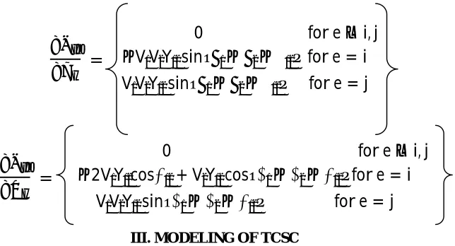
In the above equation the change in active power flow of line i-j with respect to changes in state variables is determined as :
=
0 for e
≠
i, j
−
V V Y sin
δ
−
δ
−
θ
for e = i
V V Y sin
δ
−
δ
−
θ
for e = j
=
0 for e
≠
i, j
−
2V Y cos
θ
+ V Y cos
δ − δ − θ
for e = i
V V Y sin
δ − δ − θ
for e = j
III. MODELING OF TCSC
TCSC has been modeled as a variable reactance insertedin series with the transmission line.
T
he model of TCSC is shown in Fig.2Fig 2 Equivalent circuit of a line with TCSC
=
+
=
×
whereXij is the reactance of the transmission line and rtcsc is the degree of compensation of TCSC
IV.FIREFLY ALGORITHM
FA is a nature inspired meta-heuristic algorithm which has been developedby Xin She Yang at Cambridge university in 2007.The algorithm mimics the flashing behaviour of fireflies. It is similar to other optimization algorithms employing swarm intelligence such as PSO. But FA is found to have superior performance in many cases.
• Attractiveness is proportional to their brightness, the less brighter one will be attractedtowards the brighter one. • If there are no fireflies brighter than a given firefly, it will move randomly
The number of fireflies in the swarm is known as the population size, N.The selection of population size depends on the specific optimization problem. A population size of 20 to 50 is used for PSO and FA for most applications.
Each mth firefly is denoted by a vector xm as
= [
,
, . .
]
Every time the algorithm is executed and the optimization process starts with a different setof initial points. In each case, the algorithm searches for the optimum solution. In the case of multiple possible sets of solutions, the proposed algorithm may converge on different solutions each time. Although each of those solutions will be valid as they all will satisfy the requirement. The light intensity of the mthfirefly,Im is given by
= ( )
The attractiveness between mth and nth firefly, βm,n is given by
,
=
, ,−
, ,−
,+
, ,where
,
=
‖
−
‖
=
−
rm,n = Cartesian distance between mth and nth firefly γ= Absorption parameter
k= Number of Iterations
The value of βm,n is taken as 0.2 and the value of βmax is taken as 1.γ is another constant whose value is related to the dynamic range of the solution space.The position of firefly is updated in each iterative step.If the light intensity of nth firefly is larger than the intensity of the mth firefly, then the mth firefly moves towards the nth firefly and its motion at the kth iteration is denoted by the following equation.
( ) =
(
−
1) +
,(
(
−
1)
−
( )) + (
−
0.5)
The random movement factor α is a constant whose value depends on the dynamic range of the solution space. At each
iterative step, the intensity and the attractiveness of each firefly is calculated. The intensity of each firefly is compared with all other fireflies and the positions of the fireflies are updated . After sufficient number of iterations, the global optimum is achieved.
V.PROPOSED ALGORITHM
The basic steps involved in enhancing ATC values with TCSC device using Firefly algorithm are given below: Step1:Read the system line data and bus data.
Step 2: Run the base case power flow. Step 3: Consider wheeling transactions.
Step 4: Compute AC power transfer distribution factors.
Step 6: Find the limiting element in the system buses ie, that carry power close to thermal limit. Step 7: Place TCSC in the limiting element.
Step 8: Run Firefly algorithm to obtain settings of TCSC. Step 9: Calculate ATC after incorporating TCSC.
Step 10 : Is any other transaction has to be carried, then consider the next transaction and go to step 3, otherwise stop the procedure.
VI. SIMULATION RESULTS AND DISCUSSION
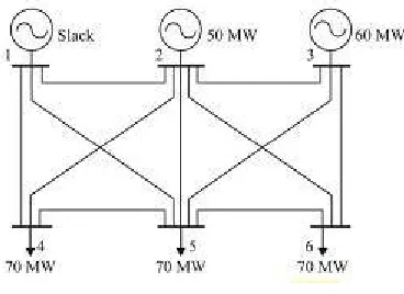
The assessment of ATC using ACPTDF method has been conducted on sample 6 bus system. It has 3 generators and 11 transmission lines.Code1, Code2, Code3 are used for slack bus,voltage-controlled buses andthe load buses respectively.
Fig.3 Sample six bus system
The optimal location obtained using firefly algorithm is line 9 (from bus 3 to bus 6 ) and the obtained ATC values after placing TCSC is as shown below.
TABLE 1
ATC – Sample 6 bus system
Line No ATC without TCSC(MW) ATC with TCSC(MW)
1 1.8477 9.5703
2 4.8971 143.2873
3 6.6850 21.9326
4 0.2996 6.4072
5 0.3731 7.5038
6 0.7902 5.0358
7 0.3227 19.3180
8 0.9326 49.0170
9 0.8381 18.6075
10 1.8575 10.1088
11 0.3426 15.9308
ATC values has enhanced when TCSC is placed in the optimal location of sample 6 bus system.
VII.CONCLUSION
programming.Simulation results shows that ATC value has enhanced when TCSC is placed at the location obtained using Firefly Algorithm.
REFERENCES
[1] Transmission Transfer Capability Task Force, “ Available transfer capability Definitions and determination”, North American Electric Reliability Council Jun. 1996.
[2] R. D. Christie, B. F. Wollenberg and I. Wangensteen, “ Transmission Management in the Deregulated Environment”,Proceedings of the IEEE ,vol. 88, no. 2, Feb. 2000.
[3] G.C. Ejebe, J. Tong, G.C.Waight, J.G. Frame, X.Wang, andW.F. Tinney, “Available transfer capability calculations”, IEEE Transactions On Power Systems, Vol. 13,No. 4,pp.1521-1527 ,Nov. 1998.
[4] G.C. Ejebe, J.G. Waight, M. Santos-Nieto, and W.F. Tinney, “Fast calculations of linear available transfer capability” in Proc. Power Industry Computer Applications Conf,pp. 255-260 , 1999.
[5] A. Kumar, S. C. Srivastva, “ AC Power Transfer Distribution Factors for Allocating Power Transactions in a Deregulated Market” IEEE Power Engineering Review, July 2012.
[6] P. Venkatesh, R. Gnanadass, N. P. Padhy, “ Available transmission capability determination using power transfer distribution factors”, International journal of emerging electric power systems, vol. 1, issue. 2, pp. 1-14, 2004.
[7] R. M. Idris, A. Kharuddin, M. W. Mustafa, “ Optimal choice of FACTS devices for ATC enhancement using Bees Algorithm”,Power Engineering Conference , pp.1–6, Sept. 2009
[8] L. J. Cay, I. Erlich,“ Optimal choice and allocation of FACTS devices using Genetic Algorithms”,EEE PES Power Systems Conference and Exposition ,pp. 201–207, 2004.
[9] M. Rashidinejad, H. Farahmand, M. F. Firuzabad, A. A. Gharaveisi,,“ ATC enhancement using TCSC via artificial intelligent techniques”,Elect. Power Sys. Res., vol.78, pp. 11–20, 2008.
[10] “ IEEE Reliability Test System”,IEEE Trans. Power App. and Syst., vol. 98, no.6, pp. 2047–2054, Nov./Dec. 1979
[11] M. A. Abido,“ Optimal Power Flow using Particle Swarm Optimisation”, International Journal of Electrical Power and Energy Systems, Vol. 24, pp. 563–571, 2002.
[12] A.A.Girgis, M.Y.Patel “ New iterative method for Available Transfer Capability calculation”, in Power and Energy Society General Meeting , IEEE, pp. 1–6 ,2011.
[13] B. V. Manikandan, S. C. Raja, P. Venkatesh and P. S. Kannan, “ Available Transfer Capability Determination in the Restructured Electricity Market”, Electrical Power Components and Systems , Vol. 36, No. 9, pp. 941–959,2008.
[14] R .Selvarasu, M.SuryaKalavathi “ SVC placement for voltage constrained loss minimization using self-adaptive Firefly algorithm”, Archives of Electrical Engineering ,Vol. 62(4), pp. 649–661 ,2013
BIOGRAPHY
AmruthaBabu, received B.Tech degree in Electrical and Electronics Engineering under Cochin University in 2012. She is currently pursuing her M.Tech in Power SystemsatSaintgits College of Engineering, Kerala, India.