Article
Vibration Control Design for a Plate Structure with
Electrorheological ATVA Using Interval Type-2
Fuzzy System
Chih-Jer Lin 1,*, Chun-Ying Lee 2 and Ying Liu 1
1 Graduate Institute of Automation Technology, National Taipei University of Technology, Taipei 10608, Taiwan; [email protected]
2 Department of Mechanical Engineering, National Taipei University of Technology, Taipei 10608, Taiwan; leech@ ntut.edu.tw
* Correspondence: [email protected]; Tel.: +886-2-2771-2171 (ext. 4328)
Abstract: This study presents a vibration control using actively tunable vibration absorbers (ATVA) to suppress vibration of a thin plate. The ATVA’s is made of a sandwich hollow structure embedded with the electrorheological fluid (ERF). ERF is considered to be one of the most important smart fluids and it is suitable to be embedded in a smart structure due to its controllable viscosity property. ERF’s apparent viscosity can be controlled in response to the electric field and the change is reversible in 10 microseconds. Therefore, the physical properties of the ERF-embedded smart structure, such as the stiffness and damping coefficients, can be changed in response to the applied electric field. A mathematical model is difficult to be obtained to describe the exact characteristics of the ERF embedded ATVA because of the nonlinearity of ERF’s viscosity. Therefore, a fuzzy modeling and experimental validations of ERF-based ATVA from stationary random vibrations of thin plates are presented in this study. Because Type-2 fuzzy sets generalize Type-1 fuzzy sets so that more modelling uncertainties can be handled, a semi-active vibration controller is proposed based on Type-2 fuzzy sets. To investigate the different performances by using different types of fuzzy controllers, the experimental measurements employing type-1 fuzzy and interval type-2 fuzzy controllers are implemented by the Compact RIO embedded system. The fuzzy modeling framework and solution methods presented in this work can be used for design, performance analysis, and optimization of ATVA from stationary random vibration of thin plates.
Keywords: Electro-Rheological fluid; Semi-active vibration control; tunable vibration absorber; type-1 fuzzy control; interval type-2 fuzzy control
1. Introduction
Smart materials and vibration control technology can suppress vibration of flight vehicles and allow them to operate beyond the traditional flutter boundary, improve ride comfort, and minimize vibration fatigue damage [1]. Due to the controllable and varied physical properties of smart materials, they are also used for living infrastructures and mechanical structures, and seismic vibration controls for decades [2-35]. Smart materials and structures that possess electromechanical characteristics have been widely used for active vibration control or semi-active vibration control, such as piezoelectric damper [4-8], eddy current damper [9], magnetostrictive spring [10], magneto-rheological fluid (MRF) damper [11-13], electro-rheological fluid (ERF) damper [14-17], shape memory alloy (SMA)[18-21], electromagnetic and piezo-electrical shunt damper [22-35]. Smart materials have one or more properties changed by the external stimuli, such as temperature, stress,
electric or magnetic fields. Active vibration control uses piezo-electrical ceramics to generate the force or displacement based on the external applied voltage [4-9]. To suppress the structure’s vibration, ERF and MRF dampers are widely used as semi-active element in suspension systems [11-17]. ER and MR fluids are transformed from the liquid state into the solid state in milliseconds by applying an electric or a magnetic field. Shape memory alloys can change its material properties based on temperature [18-21].
Since Frahm proposed the original dynamic vibration absorber (DVA) in these decades, DVAs are successfully applied in the vibration control of civil structures, naval architectures, and aerospace [36, 37]. The DVA consist of a stiffness element, a damping component, and an oscillator. The working principle of the DVA is to transfer the vibration energy to the oscillators by a specified design for a certain frequency range. Because the effective working frequency span of DVAs is narrow only for a certain designed frequency range, Den Hartog et al. considered the optimal tuning of the absorber parameters including damping to improve the DVA’s design [38]. Furthermore, the optimal determinations of parameters were investigated for the absorber with nonlinear damping and different loading characteristics in the following literatures [39]. Among the above studies, the absorbers’ parameters are constant and time invariant; therefore, the vibration absorber is passive.
To improve the performance of the passive vibration absorbers, many researchers investigated semi-active and active designs [40,41]. The semi-active absorbers have the capability of tuning their working resonant frequencies by adjusting the stiffness and/or damping of the absorbers. One of the adjustments can be realized either through the active change of geometry or through the material properties of the constituents. Thus, they are called actively tuned vibration absorbers (ATVAs) [42]. The other types of ATVA are made of the smart materials whose physical properties can be controlled by the external input. Among all ATVA designs, the ones involved with the use of smart materials, such as piezoelectric materials [4-9], magnetorheological elastomer (MRE) [12], electrorheological fluid (ERF) [16,17], and shape memory alloy and shape memory polymer [19], are frequently seen. ATVAs have advantages of being more stable in system performance and simpler in controller design.
The ER fluid consists of micrometer-size dielectric particles in insulating liquid. The ERF can change from a liquid to a gel in times of milliseconds and its apparent viscosity can be changed reversibly in response to the external electric field. Moreover, ERF can be transformed rapidly from a fluid-like state to a solid-like state as an external electric field is applied. Since the ER effect was
firstly discovered by Winslow [43], many ER systems have been developed [44-49]. The progress of
ER materials has been studied in mechanisms and properties including water-containing system such as silica gel, poly, cellulose, and water-free system such as aluminosilicate, carbonaceous,
semiconducting polymers in several literature reviews [50-55]. These reversible and controllable
al. investigated the feasibility of applying ER fluids to the vibration control of rotating flexible beams [60]. Choi et al. also proposed cylindrical ER damper suspension systems for small-sized vehicles [61]. ER fluids change from Newtonian flow to Bingham plastic with response to the applied electric field, because the electric field makes the suspended particles polarized and connected with each other to form chain. Therefore, the viscosity and the yield stress of the ER fluid increases as soon as the electric field is applied. Lin et al. studied an embedded ERF sandwich as a ATVA for a vibration control [16,17]. However, the accurate parameters of ERF models are generally difficult to obtain and the modeling uncertainties of the ATVA always exists.
Zadeh proposed sophisticated kinds of fuzzy sets, the first of which he called a type-2 fuzzy set [62]. Type-2 fuzzy sets can handle the uncertainties of the type-1 fuzzy set, because the membership functions of type-1 fuzzy sets do not have uncertainties associated with them. Even though Zadeh proposed the type-2 fuzzy sets in 1976; however, applications using type-1 fuzzy sets are much more than on type-2 fuzzy sets for decades [63]. Recently, more and more researchers around the world are studying about type-2 fuzzy sets and systems for various applications [64-72]. Different from the type-1 fuzzy set, the membership function of a general type-2 fuzzy set is three-dimensional, where the third dimension is the value of the membership function at each point on its two-dimensional domain that is called its footprint of uncertainty (FOU). To reduce the complicated computation of type-2 fuzzy set, an interval type-2 fuzzy set was proposed. For the interval type-2 fuzzy set, the third-dimension value is the same everywhere. As a result, the third dimension is ignored and only the FOU is used to describe it. Type-2 fuzzy sets are very wide applicability recently in rule-based fuzzy logic systems (FLSs), because Type-2 fuzzy sets can deal with uncertainties which cannot be modeled by type-1 fuzzy sets [63]. In this study, to improve the performance of the ATVA, a Type2-fuzzy semi-active controller is proposed to deal with the modelling uncertainties in this study.
This paper is organized as follows. Section 2 describes the fabrication of the ERF sandwich beam and the characteristic measurement of the ERF embedded ATVA in the frequency domain. It also describes the experimental setup to measure the dynamic response of the ERF embedded sandwich beam. Section 3 describes the design and analysis of a thin plate with the ERF embedded ATVA to suppress its stationary random vibration. The governing equations for this structure were derived by using principle of minimum total potential energy. The ANSYS software is used to simulate the vibration’s frequency response for the different applied electrical field to the ERF. In Section 4, the frequency response of the smart structure is measured to establish the fuzzy expert database for the vibration controller. Based on the experimental results, a Type-2 fuzzy controller is proposed to accomplish the semi-active vibration control. In Section 5, the real-time vibration control is performed to validate the proposed controller using NI compact RIO. Finally, Section 5 draws conclusions.
2. Sandwich-type ATVA with ER materials embedded
2.1. Fabrication of ER fulid and design of the sandwich ATVA with ER materials embedded
dam has four edges made of rubber and the ER fluid is confined in the volume between the rubber edges and aluminum plates. The ER fluid consists of two components: corn starch and silicon oil (KF-96-20cs), where the wight fraction of the corn-starch suspensions is almost 45%~50%. The two aluminum plates also play as the electrodes of the applied electrical field. An acrylic pad is used as the rigidity for the clamped side. The dimensions and the specifications of the ATVA are described in Table 1.
Fig. 1 Diagram and dimension of the sandwich beam with ER fluid embedded. [19]
Table 1 Specifications of the ERF sandwich beam
L W h1 w1 h2
150 mm 30 mm 0.3 mm 2.5 mm 2 mm
Adhesives ERF% Volume Weight Equivalent density
Silicone Sealant 45% 7.25 mL 28.6 g 2118.52 kg/m3
2.2. Expermental setup to measure the dynamic response of the ERF embedded sandwich beam
Figure 2 depicts a schematic diagram of the experimental setup for measuring the dynamic characteristics of the sandwich beam with ER fluid embedded. To measure the vibration response of the ERF embedded sandwich beam as the different external electrical field is applied, the experimental process is similar to our previous researches as follows [16,17].
(1) The left side of the sandwich beam is clamped by an electromagnetic vibration shaker (LDS PA500L) which provides the exciting force to the ERF embedded beam.
(2) Two non-contacting eddy-current displacement probe (Keyence AH-416) are used to measure the deflection of the input excitation (the clamped side on the shaker) and the free end of the ERF embedded beam.
(3) A high-voltage power amplifier is used to provide the electrical field to the ER fluid via the two electrodes of the aluminum plates, which is located on the left side of the ERF embedded beam. (4) When the different electric fields are applied to the ERF, a dynamic signal analyzer (HP 35665A)
is used to analyze the dynamic characteristics of the ERF sandwich beam. The vibration signal is provided to the shaker at the frequency from 0 to 200 Hz to actuate the ERF embedded beam. (5) The time response signals are captured by the dynamic signal analyzer (HP 35665A). Then, the
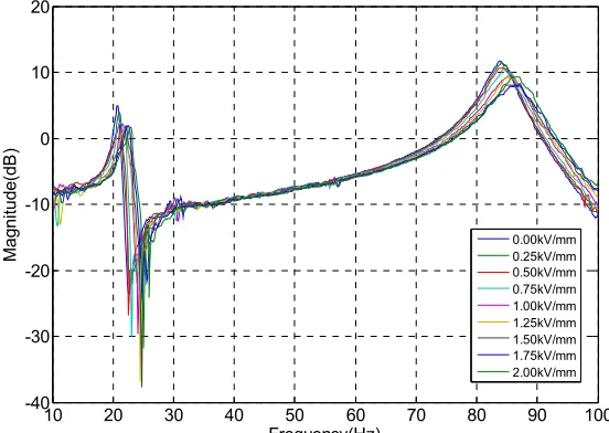
(6) Using the frequency response experiments can obtain the relationship between the frequency response and the applied electric field to the ER fluid. Based on the experiment setup of Fig. 2, Figure 3 shows the frequency response of the ERF embedded sandwich beam for the corresponding electrical field. According to the results in Fig. 3, the half-power point method is used to obtain the damping ratios for each external electrical field as shown in Table 2 [16].
Fig. 2 Schematic diagram of measuring the characteristic of the ERF sandwich beam. [16]
10 20 30 40 50 60 70 80 90 100
-40 -30 -20 -10 0 10 20
Frequency(Hz)
Ma
gn
itu
de(dB
)
0.00kV/mm 0.25kV/mm 0.50kV/mm 0.75kV/mm 1.00kV/mm 1.25kV/mm 1.50kV/mm 1.75kV/mm 2.00kV/mm
Table 2 Damping ratio according to the 1st mode frequency and its amplitude for each external electrical field. [16]
E(kV/mm) f(Hz) Amplitude
(dB)
Damping ratio(ζ)
0 20.625 5.0541 0.0235
0.25 21 3.9032 0.0233
0.5 21 2.3085 0.0342
0.75 21.125 2.4819 0.0401
1 21.375 2.2658 0.0322
1.25 21.625 0.9183 0.0383
1.5 22 1.9752 0.0295
1.75 22.375 1.9526 0.0298
2 22.75 1.7164 0.0380
3. Design and analysis of the ERF embedded ATVA for a plate structure
3.1. Governing equations of the ERF embedded beam
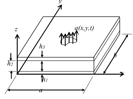
Before we investigate vibration control of a thin plate using the self-designed ERF embedded ATVA, the characteristics of the sandwich plate with ER material embedded between two plates should be studied at first. Consider a sandwich plate with ER material embedded between two face plates as shown in Fig. 4, the governing equations for this structure were derived by using principle of minimum total potential energy and written as following [14]:
Fig. 4 Schematic diagram of the sandwich plate with ER material embedded between two plates.
h
3h
1h
2a
b
x
z
y
(
)
0 1 1 2 3 1 2 1 2 1 2 1 2 1 2 1 2 1 2 2 1 2 1 2 1 1 = ∂ ∂ − − + ∂ ∂ ∂ + − + ∂ ∂ + ∂ ∂ − + ∂ ∂ x w h d G u u h G y x v G h Eh y u G h x u Eh t uh x x
ν ν ν
ρ (1)
(
)
01 1 2 3 1 2 2 1 2 2 1 2 1 2 1 1 2 1 2 1 2 1 2 1 1 = ∂ ∂ − − + ∂ ∂ − + ∂ ∂ + ∂ ∂ ∂ + − + ∂ ∂ y w h d G v v h G y v Eh x v G h y x u G h Eh t v
h y y
ν ν
ν
ρ (2)
(
)
01
1 1 3 2
2 3 2 3 2 3 2 3 2 3 2 3 2 2 3 2 3 2 3
3 ∂ =
∂ + − − ∂ ∂ ∂ + − + ∂ ∂ + ∂ ∂ − + ∂ ∂ x w h d G u u h G y x v G h Eh y u G h x u Eh t u
h x x
ν ν ν
ρ (3)
(4)
(5)
, where ρi, hi are the mass density and thickness of the ith layer, respectively.
is the height between the mid-planes of the face-plates. E, G, ν are the Young’s modulus, shear modulus and Poisson’s ratio of the plates while Gx and Gy are the shear moduli of the ER core in x and y axes, respectively. In the above equations, u1, v1, u3, v3 denote the in-plane displacements at mid-planes of the bottom and the top plates, and w represents the same lateral displacement for all three layers. It should be mentioned that only the kinetic energies associated with the displacements in three axial directions are considered whereas the rotary inertia for all layers is neglected.
3.2. Simulation study to obtain a suitable width of the ERF embedded ATVA for a plate using ANSYS In the present work, an 1-mm-thick 6061 aluminum alloy plate (shown in Figure 5) is used for studying the semi-active vibration control. Figure 5 shows that two ERF embedded ATVA are attached to the plate and the plate is made of 6061 aluminum alloy with the dimension of 200x200x0.5 (mm). In this case study, the width of the ERF embedded beam is limited in the range of 20~36 mm; to obtain the suitable width of the ERF embedded ATVA for this plate structure, the ANSYS software is used to simulate the vibration’s frequency response for the different applied electrical field to the ERF.
Fig. 5 Thin plate with the ERF embedded ATVAs
(
)
2 13 33 4 13 33 3 3 4 13 33 41 1 2 2 3 3 2 2 4 2 1 3 2 2 2 4
2
2 2 2
3 3
1 1
2 2
2 2 2 2
( ) ( ) ( ) ( )
12(1 ) 6(1 ) 3 12(1 )
y y
x x
E h h E h h E h h
w w G w w
h h h h h
t x x y y
G d u G d v
G d w w G d u v
h x h y h x x h x x
ν ρ ρ ρ ν ν ν + + + ∂ ∂ ∂ ∂ + + + + + + + + ∂ − ∂ − ∂ ∂ − ∂ ∂ ∂ ∂ + ∂ + −∂ + + −∂ +
∂ ∂ ∂ ∂ ∂ ∂ =q x y( , )
(
)
2 2 2 2
3 3 3 3 3 3
3 3 2 2 3 3 2 2 2 1 3
2 2
0
1 1
y y
G G d
v Eh u v Eh v w
h h G h G v v
t x y x y h h y
ν ρ ν ν ∂ + + ∂ + ∂ + ∂ − − + ∂ = ∂ − ∂ ∂ ∂ − ∂ ∂ 3 1 2 2 2 h h
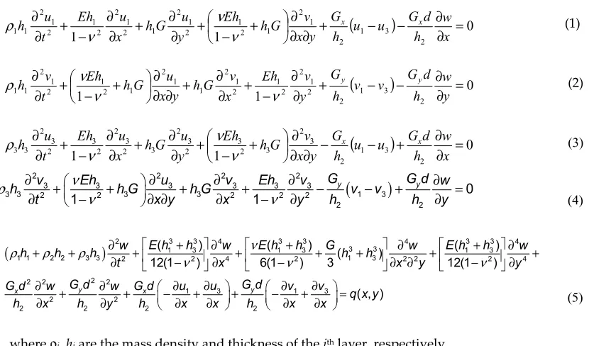
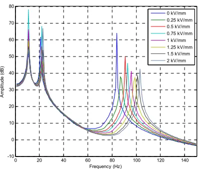
In this simulation study, the material properties of the ATVA is set up according to the viscous coefficients obtained by the previous experimental results (as shown in Table 2). Figure 6 shows the mode shapes of this plate structure with the ERF embedded ATVA at the first three vibration modes using ANSYS software. When the applied electrical fields of 0kV/mm and 2kV/mm is applied to the ERF embedded ATVA, we can obtain the frequency shifts of this structure equipped with the ERF embedded ATVA at the first three vibration models. To obtain the suitable width of the ERF embedded ATVA and its width is changed from 20 to 36 mm in the simulation studies. With the ERF embedded ATVA whose width of 20~36 (mm), Table 2 shows the resulting frequency shifts at the vibration models of this structure as the electrical field is changed from 0 to 2kV/mm. The simulation results show that the ATVA can change the resonant frequencies of the main structure as the different external electrical field is applied. Therefore, the vibration of the main structure can be controlled if the suitable electrical field is applied to the ERF embedded ATVA. Based on the simulation results in Table 2, to obtain the superior performance of suppressing vibration for the ATVA, the ATVA’s width is chosen as 36 mm in the following experimental setup, because the summation of the frequency shifts at the first three mode is maximal as w=36. With using the ANSYS software to simulate the vibration’s frequency response for the different applied electrical field to the ERF, Figure 7 shows the frequency responses of the plate structure with the ERF embedded ATVA (w=36) as the different electrical fields are applied ( 0kV/mm ~ 2kV/mm). To validate the
simulation result, the experimental setup for frequency measurements is presented in the following section.
(a) First mode (b) Second mode (c) Third mode
Fig. 6. Vibration mode shapes of this plate structure with the ERF embedded ATVA at the first three vibration modes by the simulation.
Table 3. Frequency shifts at the vibration models of this structure equipped with the ERF embedded ATVA (with the width from 20 to 36 mm) for the electrical field changed from 0 to 2kV/mm.
w(mm) 1st mode variation (Hz) 2nd mode variation (Hz) 3rd mode variation (Hz)
20 1.362 1.811 10.069
22 1.331 1.724 10.756
24 1.406 1.939 14.912
26 1.378 1.862 16.391
28 1.392 1.825 17.613
30 1.374 1.86 18.352
32 1.357 1.963 18.790
34 1.399 1.941 18.980
0 20 40 60 80 100 120 140 -10
0 10 20 30 40 50 60 70 80
Frequency (Hz)
A
m
pl
itude (
dB
)
0 kV/mm 0.25 kV/mm 0.5 kV/mm 0.75 kV/mm 1 kV/mm 1.25 kV/mm 1.5 kV/mm 2 kV/mm
Fig. 7 Simulation results of frequency responses of the plate structure with the ERF embedded ATVA (w=36) as the different electrical fields are applied
3.3. Experimental validations
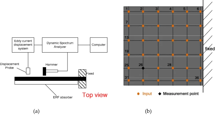
Figure 8(a) presents the schematic diagram for the experimental setup to measure the dynamic properties of the plate structure with the ERF embedded ATVA. The plate was clamped with the aluminum alloy fixture located on a cast iron platform and the impulse technique was employed in the measurement. The input excitation was provided by an impact hammer (PCB 084A17) and the induced vibration was measured by a non-contacting eddy-current displacement probe (Keyence AH-416). Both input and output signals were processed by a dynamic spectrum analyzer (Novian-N94) and the corresponding frequency response was obtained. To validate the simulation results, there are 36 points (as shown in Fig. (8b)) located at the structure for the experiments to obtain its dynamic properties. The eddy-current displacement probe is located at the 26th point and the impact hammer hits the other 35 points to obtain the frequency responses. According to the experimental results, the mode shapes of the first three modes are obtained as shown in Fig. 9. Comparing the mode shapes of simulation results (Fig. 6) with the experimental outcome (Fig. 9), we found that the experimental data was consistent with simulation results.
2kV/mm) were applied. Based on the experimental data in Table 4, the damping ratios of the ATVA can be obtained.
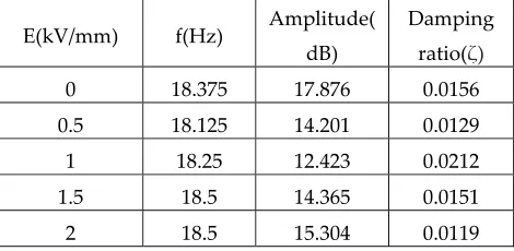
According to the experimental results in Table 4, the first-mode frequency is changed from 11.625 to 13.375 (Hz) when the external electrical field varies from 0 to 2 (kV/mm); the variation of the frequency is 15.05% and the variation of the amplitude is almost 37.01% (from 16.1 dB to 10.14 dB). In Table 5, the second-mode frequency is changed from 18.375 to 18.5 (Hz) when the external electrical field varies from 0 to 2 (kV/mm); the variation of the frequency is only 0.68%. Because the amplitude of E=0 kV/mm is 17.87dB and the amplitude of E=1 kV/mm is 12.42dB, the maximal variation of the amplitude is almost 30.49% for the second mode. In Table 6, the third-mode frequency is changed from 77 to 78.625 (Hz) when the external electrical field varies from 0 to 2 (kV/mm); the variation of the frequency is only 2.1%. Because the amplitude of E=0 kV/mm is 20.79dB and the amplitude of E=1 kV/mm is 17.41dB, the maximal variation of the amplitude is
almost 16.25% for the second mode. With observing the relation between the external electrical field and the damping coefficient of the ATVA, we found that the dynamic properties of the ERF embedded ATVA is very nonlinear. Therefore, the semi-active controller should be adaptive to
tune its damping coefficients properly according to the external vibration with different frequency. Therefore, a fuzzy modeling and experimental validations of ERF-based ATVA from stationary random vibrations of thin plates are presented in the following section.
(a) (b)
Fig. 8 Experimental setup to measure the dynamic properties of the plate structure with the ERF embedded ATVA.
first three vibration modes.
Fig. 10 Experimental setup to measure the dynamic properties of the smart structure with different external electrical filed.
Table 4.Frequency and amplitudeof the first mode vibration response for this structure equipped with the ERF embedded ATVA according to the electrical field (0 ~ 2kV/mm).
E(kV/mm) f(Hz) Amplitude
(dB)
Damping ratio(ζ)
0 11.625 16.103 0.0218
0.5 11.875 10.142 0.0140
1 12 12.677 0.0205
1.5 12.375 15.809 0.0541
2 13.375 11.629 0.0329
Table 5. Frequency and amplitude of the second mode vibration response for this structure equipped with the ERF embedded ATVA according to the electrical field (0 ~ 2kV/mm).
E(kV/mm) f(Hz) Amplitude(
dB)
Damping ratio(ζ)
0 18.375 17.876 0.0156
0.5 18.125 14.201 0.0129
1 18.25 12.423 0.0212
1.5 18.5 14.365 0.0151
2 18.5 15.304 0.0119
Table 6.Frequency and amplitudeof the third mode vibration response for this structure equipped with the ERF embedded ATVA according to the electrical field (0 ~ 2kV/mm).
E(kV/mm) f(Hz) Amplitude(
dB)
Damping ratio(ζ)
0 77 20.795 0.0083
0.5 77.625 19.547 0.0087
1 77.875 17.414 0.0108
1.5 78.125 18.382 0.0122
4. Semi-active vibration control of the thin plate using the ERF embedded ATVA
4.1. Experimental setup for the thin plate with board-band vibrations
In our previous research, we have designed a semi-active controller for the cantilever beam equipped with the ERF embedded ATVA for the vibration at specified frequencies []. However, the thin plate’s vibration mode shape is different from the cantilever beam. Fig. 9 shows the plate’s vibration modes, where the locations with the maximum displacement vary with the vibration modes. As shown in Fig. 9(a), the first mode shape of the plate is similar to the one of the cantilever beam; the maximum displacement appears at the free end. Therefore, to measure the vibration of the first mode, the displacement sensor can be located at the line of the free end.
However, as shown in Fig. 9 (b), the maximum displacement of the second mode appears at the both side of the free end. If we need to measure the vibrations of the first and second modes, the middle point of the free end is not a good choice to locate the displacement sensor. Even though the middle point of the free end can measure the vibration of the first mode, this location is not sensitive to the vibration of the second mode. As a result, to measure the vibration of the second mode, the displacement sensor should be located at the both side of the free end. With observing the mode shape of the third mode in Fig. 9 (c), we found that the location with the maximum displacement appears at the middle point of the free end for the third vibration mode. Therefore, to measure the vibration of the third mode, we need to locate the sensor at the middle point to obtain the better sensitivity to the vibrations. Obviously, the choice of displacement sensor’s location of the third mode is in conflict with the ones of the first and second modes.
With consideration of measuring the board-band vibrations, we proposed to use two displacement sensors to measure the response of the plate for the different vibration modes. On one hand, an eddy-current displacement sensor is located at the upper side of the free end to measure the vibrations of the first and second modes; on the other hand, the other displacement sensor is located at the middle of the free end to measure the vibration of the third mode. Figure 11 shows the schematic diagram of semi-active vibration control architecture for the ERF embedded ATVA. Two eddy-current displacement sensors are located at the middle and the upper of the free end to measure the vibration of the plate; the embedded controller (cRIO-9074) is used to implement the real-time control system. The analog input module (NI 9234) is used to capture the feedback signals of the displacement sensors and the analog output module (NI 9263) is used to provide the analog signal according to the proposed semi-active vibration controller. Then, the output signal of NI 9263 is amplified via the high-voltage power amplifier (Trek 609A) to produce the required electrical field to the ERF material.
Fig. 11 Experimental schematic diagram of semi-active vibration control architecture for the ERF embedded ATVA.
4.2. Semi-active vibration control using the interval type-2 fuzzy
The fuzzy rules of semi-active control are usually obtained by the expert database or the relation between input and output by experimental results []. In this paper, to establish the fuzzy controller’s rule bass at the different frequencies, we measure the vibration response of the structure with the ERF ATVA with different applied electrical field at different frequency; then, according to the experimental results, the optimal electrical field at the different frequency is recorded to establish the expert database of the fuzzy rules.
In all experiments, a sinusoidal signal is input to the shaker’s amplifier at follows.
)
2
sin(
)
(
t
A
ft
r
=
π
, where A is the amplitude of the input signal and f is the frequency of the sinusoidal signal.
The signal is amplified to drive the electromagnetic vibration shaker (LDS PA500L) and then the shaker provides the stimulating vibration to the structure. Consequently, the electrical field of the ATVA is tuned at the different levels of 0~2 (kV/mm) to perform the vibration experiments; the vibration displacement of the structure is measured by the eddy-current displacement sensors and recorded by the NI CRIO 9074 simultaneously.
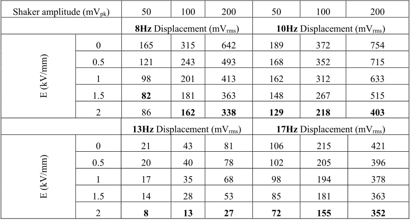
For the first mode of vibration with the frequency range of 8 ~17 (Hz), the experimental results show that the ATVA has the better performance with the larger external electrical field. This experimental results imply that the ATVA has the better ability of absorbing vibration if its viscous coefficient is larger for the frequencies at the first vibration mode. However, for the second mode of vibration, the optimal external electric field is different from the first mode. With the exception of the vibration at the frequency of 21 (Hz), the ATVA has the better ability of absorbing vibration with the smaller electrical field at the frequencies of 19, 23 and 25 (Hz). With the vibration at the frequency of 21 (Hz), the ATVA with the electrical field of E=1 (Kv/mm) has the better ability of absorbing vibration than the others.
In addition, for the third vibration mode, the ability of absorbing vibration for the ATVA is changed again. According to the experimental results in Tables 9, with the exception of the vibration at the frequency of 88(Hz), the ATVA has the better ability of absorbing vibration with the electrical field of E=1.5 (Kv/mm) for the vibration with the frequency of 74, 76, and 78 (Hz). From the experimental results in Tables 7-9, it is obvious that the relation between the optimal electrical field and the vibration frequency of the smart structure is nonlinear. In some cases, the amplitude of vibration is also influence the performance of the proposed ATVA. Therefore, we need to design a semi-active vibration controller to produce the optimal electrical field with respect to the vibration. Because of the nonlinear relation between the optimal electrical field and the ability of absorbing vibration, a type-2 fuzzy controller is proposed to establish the input-output mapping according to the experimental results.
Table 7. Frequency responses of this smart structure with respect to the different external electrical field applied to ERF for the external vibration at 8~17Hz.
Shaker amplitude (mVpk) 50 100 200 50 100 200
8HzDisplacement (mVrms) 10Hz Displacement (mVrms)
E (kV/mm)
0 165 315 642 189 372 754
0.5 121 243 493 168 352 715
1 98 201 413 162 312 633
1.5 82 181 363 148 267 515
2 86 162 338 129 218 403
13Hz Displacement (mVrms) 17Hz Displacement (mVrms)
E (kV
/mm)
0 21 43 81 106 215 421
0.5 20 40 78 102 205 396
1 17 35 68 98 194 378
1.5 14 28 53 85 181 363
Table 8. Frequency responses of this smart structure with respect to the different external electrical field applied to ERF for the external vibration at 19~25Hz.
Shaker amplitude (mVpk) 50 100 200 50 100 200
19Hz Displacement (mVrms) 21Hz Displacement (mVrms)
E (kV/mm)
0 33 75 153 28 54 110
0.5 36 77 158 25 52 106
1 37 78 159 26 53 108
1.5 39 80 161 27 53 107
2 38 80 162 28 54 111
23Hz Displacement (mVrms) 25Hz Displacement (mVrms)
E (kV/m
m
) 0 21 41 80 16 34 69
0.5 22 41 82 17 34 70
1 22 41 81 16 34 71
1.5 22 41 83 17 35 70
2 23 42 83 18 35 73
Table 9 Frequency responses of this smart structure with respect to the different external electrical field applied to ERF for the external vibration at 74~80Hz.
Shaker amplitude (mVpk) 50 100 200 50 100 200
74Hz Displacement (mVrms) 76Hz Displacement (mVrms)
E (k
V/
mm
) 0 6 11 21 15 28 55
0.5 5 9 16 14 26 47
1 4 7 13 9 20 39
1.5 3 6 12 8 19 37
2 5 8 14 10 20 37
78Hz Displacement (mVrms) 80Hz Displacement (mVrms)
E (
kV/mm)
0 26 53 104 15 30 61
0.5 18 33 68 15 30 60
1 16 29 58 20 41 78
1.5 14 23 47 23 46 87
2 17 28 59 24 48 97
Type-2 fuzzy controller design for ATVA:
0 100 200 300 400 500 600 700 800 900 1000 0
0.1 0.2 0.3 0.4 0.5 0.6 0.7 0.8 0.9 1
D
rms
Memb
e
rsh
ip
fuzzy sets. First, the first mode of vibration is considered, a Gaussian function with a known standard deviation and a uniform weighting were used to represent a footprint of uncertainty as shaded in Fig. 12. Because of using such a uniform weighting, it is usually called an interval type-2 fuzzy set (IT2FS) [49]. For the IT2FS, a type-reducer is needed to convert to a type-1 fuzzy set before defuzzification is carried out as shown in Fig. 13. To obtain the output of the IT2FS, we need two fuzzy rule tables; however, the same fuzzy rule table is used in this case as shown in Table 10. After obtaining the inference output, the type-reducer and defuzzifier are used to obtain the input-output
relation and the two signals ( , f) were fed back to the proposed fuzzy controller.
Fig. 12. Type-2 fuzzy Membership function for the two inputs: (a) the root-mean-square (rms) value of displacement; (b) vibration frequency.
Table 10. Right and left fuzzy rule tables for the first mode
f drms VS S M
VS B VB VB
S VB VB VB
M M VB M
Fig. 13. Main inference structure of Type-2 fuzzy
0 2 4 6 8 10 12 14
0 0.1 0.2 0.3 0.4 0.5 0.6 0.7 0.8 0.9 1
f (Hz)
Memb
e
rs
For type-2 fuzzy system, Fig. 14 shows the inference operation to obtain the output by using the following equations. After obtaining the inference output, we used the type-reducer and defuzzifier to obtain the input-output relation as shown in Fig. 15.
1
( ) N
i A i
f u x
=
=
∏
(7)1
( ) N
A i i
f u x
=
=∏ (8)
, where N is the number of the inputs.
f
f
1
f
2
f
1
f
2
f
Fig. 14. Inference operation to obtain the output.
As shown in Fig. 15, we can the optimal voltage by the input-output lookup relation of the fuzzy controller. Then, the proposed semi-active vibration controller generates the required voltage through the high voltage power amplifier to actuate the ATVA for absorbing vibration. According to Table 8-10, the input-output relation of the type-2 fuzzy controller are shown in Fig. 16 for the second and third modes. It is obvious that the fuzzy rules are different from the fuzzy rule of the first vibration mode. Therefore, for the different vibration mode, we should tune the electrical field
Fig. 15. Main inference structure of the proposed Type-2 fuzzy controller of the first mode.
(a)
(b)
Fig. 16. Main inference structure of the proposed Type-2 fuzzy controller of the second and third mode.
4.3. Semi-active vibration controller with a switching-mode rule for ATVA
Because of the nonlinear dynamic properties of the ERF embedded ATVA with response to the vibration at different frequencies, a semi-active vibration control with a switching-mode rule is proposed to determine the optimal electrical field for the ATVA. There are two reasons why the switching action is necessary. The first reason is that the location with the maximum displacement may vary for the different vibration mode. Therefore, in Section 4.1, we proposed to use two displacement sensors to measure the response of the plate for the different vibration mode to obtain the better vibration measurement. The second reason is that the electrical field of the ATVA should be adaptively tuned for the different vibration mode (as shown in Fig. 14-15) to obtain the superior ability of absorbing vibration for the ATVA. Therefore, we proposed a fuzzy controller of the ATVA
for attenuating the undesired vibration by using the frequency-dependent control strategy [7]. Fig. 17 shows the proposed switching algorithm of the fuzzy controller according to the frequency response to tune the electrical field adaptively and Fig. 18 is the real-time embedded code for the NI
look-up tables as shown in Fig. 15-16. Second, the displacements of the structure is captured by the CRIO 9074. Third, the vibration frequency is obtained from the FFT of the displacements. Then, the real-time program uses the resulting frequency to distinguish which the vibration mode is and it switch the input to the suitable controller to produce the control voltage.
Fig. 17. Proposed switching algorithm of the fuzzy controller according to the frequency response.
Switch the control By Frequency Fuzzy controller
for each mode
5. Experimental results and discussion
Case I: External vibration at the specified frequency
The excitation signals at the frequencies from 8 to 78 (Hz) are inputted to the shaker to vibrate the structure to validate the proposed semi-active controller. To compare the performance of the proposed controller for different vibration modes, we designed five case studies to investigate the vibration absorbing ability of the ATVA. Figs. 19-21 compare the vibration responses with no control with the ones of the proposed controller at the frequency of 8, 10, 18, 20, 75 and 77 (Hz), where the fuzzy controller is turned on at t=2.5 (sec). The vibration reduction rate (VRR) is defined as follows.
With the external vibration at the frequency close to the first vibration mode of the structure, Fig. 19 shows that the type-2 fuzzy controller has the better vibration-reduction ability with the frequency of 8(Hz), whose VRR is 81.5%. The VRR with the frequency of 8 Hz is better than the one with the frequency of 10 (Hz), whose reduction rate is 36.1%. When the external vibration’s frequency is close to the second vibration mode, Fig. 20 shows that the proposed controller has the VRR of about 40%. With the external vibration at the frequency close to the third mode of the structure, Fig. 21 shows that the proposed type-2 fuzzy controller has the best performance at the frequency of 77(Hz), whose VRR is about 89%. Table 11 summarizes the results at the frequencies of 8, 10, 18, 20, 75 and 77 (Hz) using the proposed controller, the experimental results is compared with the ones using type-1 fuzzy controller [16] in the previous studies. According to the experimental results, the proposed type-2 fuzzy controller has the better performance of absorbing vibration than the type-1 fuzzy control.
Table 11. Experimental results at the frequencies of 8, 10, 18, 20, 75 and 77 (Hz) using the type-1 and type-2
fuzzy controller.
Frequency Type-1 Fuzzy controller
Type-2 Fuzzy controller
8Hz 81.4% 81.5%
10Hz 19.9% 36.1%
18Hz 38.3% 40.9%
20Hz 24.8% 40.3%
77Hz 88.6% 89.7%
79Hz 37.3% 54.2%
= RMS value of the amplitude with vibration control
VRR
0 4 8 -0.6 -0.3 0 0.3 0.6 D is pla ce me nt ( mm) Time (s) Type-2 (8Hz)
0 4 80
0.5 1 1.5 2 El ec tr ic F ie ld ( kV/ m m ) Displacement Electric Field
0 4 8
-0.6 -0.3 0 0.3 0.6 Di sp la ce m en t ( m m ) Time (s) Type-2 (10Hz)
0 4 80
0.5 1 1.5 2 E lec tr ic F iel d (k V /m m ) Displacement Electric Field
Fig. 19. Experimental results of the smart structure for the external vibration at 8 and 10 (Hz) with the stimulating signal of 200mVpk.
0 4 8
-0.4 -0.2 0 0.2 0.4 D is pl ac em ent ( m m ) Time (s) Type-2 (18Hz)
0 4 80
0.5 1 1.5 2 E lec tr ic F ie ld (k V /m m ) Displacement Electric Field
0 4 8
-0.2 -0.1 0 0.1 0.2 D is pl ac em ent ( m m ) Time (s) Type-2 (20Hz)
0 4 80
0.5 1 1.5 2 E lec tr ic F ie ld ( kV /m m ) Displacement Electric Field
Fig. 20. Experimental results of the smart structure for the external vibration at 18 and 20 (Hz) with the stimulating signal of 200mVpk.
0 4 8
-0.1 -0.05 0 0.05 0.1 D is pla ce me nt ( mm) Time (s) Type-2 (75Hz)
0 4 80
0.5 1 1.5 2 E lec tr ic F iel d (k V /m m ) Displacement Electric Field
0 4 8
-0.6 -0.3 0 0.3 0.6 D is pl ac eme nt ( mm) Time (s) Type-2 (77Hz)
0 4 80
0.5 1 1.5 2 E le ct ric Fie ld ( kV /m m ) Displacement Electric Field
Fig. 21. Experimental results of the smart structure for the external vibration at 75 and 77(Hz) with the stimulating signal of 200mVpk.
Case II: External vibration with the varying frequency
shows the time response of the structure’s displacement for the real-time experiment. Fig. 22 validates that the proposed fuzzy controller has the adaptive ability to suppress vibration efficiently and rapidly, even if the frequency of external vibration is changed. Figure 22 shows that the VRR of the proposed control at the frequency of 8 (Hz) is almost 86.5% with the electrical field output of 2kV/mm, which is consistent with the previous result in Fig. 19. The electrical field output of 1.8 (kV/mm) is obtained by the proposed controller and the VRR of 16 (Hz) is almost 29.4%. Therefore, the experimental result shows that the proposed controller validates the vibration reduction ability for the external vibration with the multiple frequencies of 8 and 16 Hz. From the above experimental results, we found the fact that the proposed ATVA has the superior ability of absorbing vibration for this plate at the first and third vibration modes (8 Hz and 77 Hz). For the second mode, the VRR of the ATVA is reduced from 81.5% (for the first mode) to 40.9%. Expect for the vibration frequency of 8 Hz, the proposed type-2 fuzzy controller has the better VRR than the type-1 fuzzy control.
0 1 2 3 4 5 6 7 8
-4 -2 0 2 4
D
isp
la
ce
m
en
t (
m
m
)
Time (s)
0 1 2 3 4 5 6 7 80
0.5 1 1.5 2
E
lec
tr
ic
F
iel
d (k
V
/m
m
)
Uncontrolled Type-2 fuzzy control Electric field
Fig. 21. Time response of the structure’s displacement for the real-time experiment for the external vibration with the varying frequencies.
5. Conclusions
vibration mode. For the second vibration model, the VRR of the plate structure using the proposed ATVA is 40.9%. The proposed type-2 fuzzy controller has the best performance at the frequency of 77(Hz), whose VRR is about 89%. The experimental results verified the effectiveness of the proposed semi-active vibration controller using the interval type-2 fuzzy system.
Acknowledgments: The authors would like to thank the National Science Council of the Republic of China, Taiwan for financially/partially supporting this research under Contract No. MOST 104-2221-E-027-026 and MOST 105-2221-E-027-041.
Author Contributions: Chih-Jer Lin conceived and designed the experiments; Chun-Ying Lee contributed reagents/materials/analysis tools; Ying Liu performed the experiments and analyzed the data; Chih-Jer Lin wrote the paper.
References
1. Carlson, J.D.; Catanzarite, D. M.; St. Clair, K. A. Commercial magneto-rheological fluid device, Proc. 5th Int. Conf. ER Fluids, MR Fluids Associated Technol., 1995, 20–28.
2. Giurgiutiu, V. Review of Smart-Materials Actuation Solutions for Aeroelastic and Vibration Control.
Journal of Intelligent Material Systems and Structures 2000, 11, 525-544.
3. Valliappan, S.; Qi K. Review of seismic vibration control using ‘smart materials’. Structural Engineering and Mechanics 2001, 11(6), 617-636.
4. Vautier, B.J.G.; Moheimani, S.O.R. Vibration reduction of resonant structures using charge controlled piezoelectric actuators. Electron. Lett.2003, 39, 1036–1038.
5. Moheimani, S.O.R.; Vautier, B.J.G. Resonant control of structural vibration using charge-driven piezoelectric actuators. IEEE Trans. Control Syst. Technol.2005, 13, 1021–1035.
6. Rodriguez-Fortun, J.M.; Orus, J.; Alfonso, J.; Gimeno, F.B.; Jose, A.; Castellanos, J.A. Flatness-Based Active Vibration Control for Piezoelectric Actuators. IEEE/ASME Trans. Mech.2013, 18, 221–229.
7. Steiger, K.; Mokrý, P. Finite element analysis of the macro fiber composite actuator: Macroscopic elastic and piezoelectric properties and active control thereof by means of negative capacitance shunt circuit.
Smart Mater. Struct.2015, 24, 025026.
8. Zhang, S.; Yan, B.; Luo, Y.; Miao, W.; Xu, M. An Enhanced Piezoelectric Vibration Energy Harvesting System with Macro Fiber Composite. Shock Vib. 2015, 2015, 916870.
9. Beek, T.V.; Pluk, K.; Jansen, H.; Lomonova, E. Optimisation and measurement of eddy current damping in a passive tuned mass damper. IET Electr. Power Appl.2016, 10, 641–648.
10. Scheidler, J.J.; Asnani, V.M.; Dapino, M.J. Dynamically tuned magnetostrictive spring with electricallycontrolled stiffness. Smart Mater. Struct. 2016, 25, 035007.
11. Olabi, A. G.; Grunwald A. Design and application of magnetorheological fluid. Mater. Design 2007, 28, 2658–2664.
12. Weber, F.; Maslanka, M. Frequency and damping adaptation of a TMD with controlled MR Damper.
Smart Materials and Structures2012, 21, 055011 (17 pp).
13. Lin, C.J.; Yau, H.T.; Lee, C.Y.; Tung, K.H. System Identification and Semiactive Control of a Squeeze-Mode Magnetorheological Damper.IEEE/ASME Trans. Mech.2013,18, No. 6, pp. 1691-1701. 14. Lee, C. Y.; Cheng, C. C.; Dynamic Characteristics of Sandwich Beam with Embedded Electro-Rheological
Fluid. Journal of Intelligent Material Systems and Structures1998,9(1), pp.60-68.
15. Sun Y.; Thomas M. Control of torsional rotor vibrations using an electrorheological fluid dynamic absorber. Journal of Vibration and Control2011,17, pp. 1253–1264.
16. Lin, C.J.; Lee, C.Y.; Cheng, C.H.; Chen, G.F. Vibration Control of a Cantilever Beam Using a Tunable Vibration Absorber Embedded with ER Fluids. International Journal of Mechanical, Aerospace, Industrial, Mechatronic and Manufacturing Engineering2013,7, No. 7, pp. 1412-1418.
17. Lin, C.J.; Lee, C.Y.; Liu, Y.; Cheng, C.H. Interval Type-2 Fuzzy Vibration Control of a ERF Embedded Smart Structure. International Science Index, Mechanical and Mechatronics Engineering 2014, 8, No:7, pp. 1215-1221.
18. Song, G.; Ma, N.; Li, H.-N. Applications of shape memory alloys in civil structures. Eng. Struct. 2006, 28, 1266–1274.
19. Lee, C.Y.; Chen, C.C.; Yang, T.H.; Lin, C.J. Structural vibration control using a tunable hybrid shape memory material vibration absorber. Journal of Intelligent Material Systems and Structures 2012, 23, pp. 1725–1734.
20. Damanpack, A.R.; Bodaghi, M.; Aghdam, M.M.; Shakeri, M. On the vibration control capability of shapememory alloy composite beams. Compos. Struct. 2014, 110, 325–334.
21. Lee, C.Y.; Pai, C.A. Design and implementation of tunable multi-degree-of-freedom vibration absorber made of hybrid shape memory helical springs. Journal of Intelligent Material Systems and Structures2016,27, No. 8, pp. 1047–1060, DOI: 10.1177/1045389X15581519
22. Soltani, P.; Kerschen, G.; Tondreau, G.; Deraemaeker, A. Piezoelectric vibration damping using resonant shunt circuits: An exact solution. Smart Mater. Struct.2014, 23, 125014.
23. Guo, K.; Jiang, J. Independent modal resonant shunt for multimode vibration control of a truss-cored sandwich panel. Int. J. Dyn. Control 2014, 2, 326–334.
25. Qureshi, E.M.; Shen, X.; Chen, J. Vibration control laws via shunted piezoelectric transducers: A review.
Int. J. Aeronaut. Space Sci.2014, 15, 1–19.
26. Yan, B.; Luo, Y.; Zhang, X. Structural multimode vibration absorbing with electromagnetic shunt damping. J. Vib. Control2016, 22, 1604–1617.
27. Necasek, J.; Vaclavik, J.; Marton, P. Digital synthetic impedance for application in vibration damping. Rev. Sci. Instrum. 2016, 87, 024704.
28. Christopher Robert, K.; Jeffrey, K. Adaptive Synchronized Switch Damping on an Inductor: A Self-Tuning Switching Law. Smart Mater. Struct.2016. acceped.
29. McDaid, A.J.; Mace, B.R. A Robust Adaptive Tuned Vibration Absorber Using Semi-Passive Shunt Electronics. IEEE Trans. Ind. Electron. 2016, 63, 5069–5077.
30. Tao, J.; Jing, R.; Qiu, X. Sound absorption of a finite micro-perforated panel backed by a shunted loudspeaker. J. Acoust. Soc. Am. 2014, 135, 231–238.
31. Shen,W.; Zhu, S.; Zhu, H.; Xu, Y.-L. Electromagnetic energy harvesting from structural vibrations during earthquakes. Smart Struct. Syst. 2016, 18, 449–470.
32. Yan, B.; Zhang, S.; Zhang, X.; Wang, C.; Wu, C. Self-powered electromagnetic energy harvesting for the low power consumption electronics: Design and experiment. Int. J. Appl. Electromagn. Mech. 2017, 1–11. 33. Pérez-Díaz, J.; Valiente-Blanco, I.; Cristache, C. Z-Damper: A New Paradigm for Attenuation of
Vibrations. Machines2016, 4, 12.
34. Vaclavik, J.; Kodejska, M.; Mokry, P.Wall-plug efficiency analysis of semi-active piezoelectric shunt damping systems. J. Vib. Control 2016, 22, 2582–2590.
35. Yan, B.;Wang, K.; Hu, Z.;Wu, C.; Zhang, X. Shunt Damping Vibration Control Technology: A Review.
Appl. Sci.2017, 7, 494; doi:10.3390/app7050494.
36. Frahm, H. Device for damping vibrations of bodies. US patent no. 989958, 1911.
37. Korenev, B.G.; Reznikov, L.M. Dynamic Vibration Absorbers, Theory and Technical Applications, Wiley, New York, 1993.
38. Den Hartog, J. P. Mechanical vibration. 4th ed. Dover Publication, New York, 1985.
39. Zilletti, M.; Elliott, S.J.; Rustighi, E. Optimisation of dynamic vibration absorber to minimize internal power dissipation. J. Sound Vib.2012,331, pp. 4093–4100.
40. Kela, L.; Vahaoja, P. Recent studies of adaptive tuned vibration absorbers/neutralizers. Appl. Mech. Rev. 2009, 62, pp. 060801-1_060801-9.
41. Brennan, M. J. Some recent developments in adaptive tuned vibration absorbers/neutralizers. Shock Vib. 2006,13, pp. 531–543.
42. Ghorbani-Tanha, A.K.; Rahimian, M.; Noorzad, A. A novel semiactive variable stiffness device and its application in a new semiactive tuned vibration absorber. Journal of Engineering Mechanics2011,137, pp. 390–399.
43. Winslow, W. M. Induced Fibration of Suspensions. Journal of AppliedPhysics 1949,Vol. 20, pp.1137-1140. 44. Yin, J.B.; Zhao X.P. Electrorheology of nanofiber suspensions. Nanoscale Research Letters2011, 6, 256. 45. Conrad; H. Sprecher, A.F. Characteristics and mechanisms of electrorheological fluids. J Stat Phys1991,
64:1073.
46. Weiss, K.D.; Coulter, J.P.; Carlson, J.D. Electrorheological fluid under elongation, compression and shearing. J Intell Mater Syst Struct1993, 4:13.
47. Block, H.; Rattray, P. Recent developments in ER fluids. In Progress in Electrorheology. Edited by: Havelka KO, Filisko FE. New York: Plenum Press; 1995:19-42.
48. See, H. Advances in modeling the mechanisms and rheology of electrorheological fluids. Korea-Australia Rheol J1999,11:169.
49. Hao, T. Electrorheological suspensions. Adv Colloid Interface Sci 2002,97:1.
50. See, H. Advances in electro-rheological fluids: Materials, modelling and applications. J Ind Eng Chem2004, 10:1132.
51. Sung, J.H.; Cho, M.S.; Choi, H.J.; Jhon, M.S. Electrorheology of semiconducting polymers. J Ind Eng Chem 2004,10:1217.
52. Zhao, X.P.; Yin, J.B. Advances in electrorheological fluids based on inorganic dielectric materials. J Ind Eng Chem2006,12:184.
54. Zhao, X.P.; Yin, J.B.; Tang, H. New advances in design and preparation of electrorheological materials and devices. In Smart Materials and Structures: New Research. Edited by: Reece PL. New York: Nova Science Publishing 2007; pp. 1-66.
55. Kim, D.H.; Kim, Y.D. Electrorheological properties of polypyrrole and its composite ER fluids. J Ind Eng Chem2007, 13:879.
56. Choi, H.J.; Jhon, M.S. Electrorheology of polymers and nanocomposites. Soft Matter2009, 5:1562.
57. Choi, S. B.; Park, Y. K.; Cheong, C. C. Active vibration control of intelligent composite laminate structures incorporating an electro-rheological fluid. J. Intell. Mater. Syst. Structures 1996,7, pp.411-419.
58. Yalcintas, M.; Coulter, J. P.; Don, D. L. Structural modeling and optimal control of electro-rheological material based adaptive beams. Smart Mater. Struct.1995,4, pp.207-214..
59. Rahn, C. D.; Joshi, S. Modeling and control of an electro-rheological sandwich beam. J. Vib. Acoust.1998,
120, pp.221-227.
60. Wei,K. X.; Meng, G. W.; Zhang, M. Vibration characteristics of a rotating beam filled with electrorheological fluid. J. Intell. Mater. Syst. Structures 2007,18, pp.1165-1173.
61. Choi, S.B.; Han, Y.M.; Sung, K.G. Vibration Control of Vehicle Suspension System Featuring ER Shock Absorber. Int J Appl Electrom2008,27, pp. 189-204.
62. Zadeh, L. A. The concept of a linguistic variable and its application to approximate reasoning-I. Inf. Sci. 1975,8, pp.199-249.
63. Mendel, J. M. Uncertain Rule-Based Fuzzy Logic Systems: Introduction and New Directions, Prentice-Hall, Upper-Saddle River, NJ, 2001.
64. Kovacic, Z.; Balenovic, M.; Bogdan, S. Sensitivity based self learning fuzzy logic control for a servo system.
IEEE Control Syst. Mag.1998, 18 (3), pp. 41-51.
65. Lee, H.; Tomizuka, M. Robust adaptive control using a universal approximator for SISO nonlinear systems.
IEEE Trans. Fuzzy Syst.2000,8 (1), pp. 95-106.
66. Wang, J. S.; Lee, C.S. Self-adaptive neuro-fuzzy inference systems for classification application. IEEE Trans. Fuzzy Syst. 2002,10 (6), pp. 790-802.
67. Golea, N.; Golea, A.; Benmahammed, K. Fuzzy model reference adaptive control. IEEE Transactions on Fuzzy Systems 2002,10 (4), pp. 436-444.
68. Hojati, M.; Gazor, S. Hybrid adaptive fuzzy identification and control of nonlinear systems. IEEE Trans. Fuzzy Syst.2002,10 (2), pp. 198-210.
69. Mendel, J. M. Fuzzy Sets for Words: a New Beginning. Proc. IEEE FUZZ Conference, St. Louis, MO, May 26–28, 2003, pp. 37–42.
70. Mendel, J. M. Computing derivatives in interval type-2 fuzzy logic systems. IEEE Trans. Fuzzy Syst.2004, 12 (1), pp. 84-98.
71. Wang, C. H.; Cheng, C. S.; Lee, C. T. Dynamical optimal training for interval type-2 fuzzy neural network (T2FNN). IEEE Trans. Syst. Man Cybern.Part B2004, 34 (3), pp. 1462-1477.