© 2017, IRJET | Impact Factor value: 5.181 | ISO 9001:2008 Certified Journal
| Page 1341
DIA-GRID STRUCUTURES
DEEP BAJORIA
1, GAURAV BANWAT
2, AVISHEKH JAISWAL
3, SAURABH AGARWAL
1,2,3,4
Student, Dept. of Civil Engineering, MAEER’S MIT College of Engineering, Maharashtra, India
---***---Abstract –One of the evocative structural design solutions for tall buildings is recently embraced by the diagrid (diagonal grid) structural system. In tall buildings, the main problem that governs the design is lateral loads, instead of the gravitational loads in shorter building. Thus, systems that are more efficient in achieving stiffness against lateral loads are considered better options in designing tall buildings. The diagrid system is one of the most efficient lateral resisting systems, and this feature is caused by its triangular configurations. The diagrid structural system has been widely used for recent tall buildings due to the structural efficiency and aesthetic potential provided by the unique geometric configuration of the system. This paper presents a stiffness-based design methodology for determining preliminary member sizes of R.C.C. diagrid structures for a G+36 story building. The methodology is applied to the diagrid to determine the optimal grid configuration of the diagrid structure and further its comparison with conventional R.C.C structure.
A regular floor plan of 36 m × 36 m size is considered for the structures. ETABS 9.7.4 software is used for modelling, analysis and design of structural members. All structural members are designed as per IS 456:2000 and load combinations of seismic forces are considered as per IS 1893(Part1):2002 considering all load combinations. Dynamic load along wind and across wind are considered for analysis for the structure as per IS 875-1987 (part 3). Analysis of G+36 story building with perimeter diagrid is carried out by Response spectrum method. The comparison of analysis of results in terms of top story displacement, story drift, story shear, time period, steel and concrete consumption, base reactions for seismic and wind forces is done.
Key Words: Simple structure, Diagrid structure, ETABS analysis.
1. INTRODUCTION
The rapid growth of urban population and consequent pressure on limited space have considerably influenced the residential development of city. The high cost of land, the desire to avoid a continuous urban sprawl, and the need to preserve important agricultural production have all contributed to drive residential buildings upward. As the height of building increase, the lateral load resisting system becomes more important than the structural system that resists the gravitational loads. The lateral load resisting systems that are widely used are: rigid frame, shear wall,
wall-frame, braced tube system, outrigger system and tubular system. Recently, the diagrid – Diagonal Grid – structural system is widely used for tall steel buildings due to its structural efficiency and aesthetic potential provided by the unique geometric configuration of the system.
Diagrid has good appearance and it is easily recognized. The configuration and efficiency of a diagrid system reduce the number of structural element required on the façade of the buildings, therefore less obstruction to the outside view. The structural efficiency of diagrid system also helps in avoiding interior and corner columns, therefore allowing significant flexibility with the floor plan. Perimeter “diagrid” system saves approximately 20 percent of the structural steel weight when compared to a conventional moment-frame structure.
The diagonal members in diagrid structural systems can carry gravity loads as well as lateral forces due to their triangulated configuration. Diagrid structures are more effective in minimizing shear deformation because they carry lateral shear by axial action of diagonal members. Diagrid structures generally do not need high shear rigidity cores because lateral shear can be carried by the diagonal members located on the periphery. Hence, the diagrid, for structural effectiveness and aesthetics has generated renewed interest from architectural and structural designers of tall buildings.
2. METHODOLOGY
© 2017, IRJET | Impact Factor value: 5.181 | ISO 9001:2008 Certified Journal
| Page 1342
different story module is carried out by Response spectrum method. The comparison of results of
analysis in terms of top story displacement, story drift, story shear, time period, angle of diagrid, base shear and story shear for seismic and wind forces is done and these properties are compared with conventional structure to determine the effectiveness of diagrid structure.
2.1 Stiffness based design methodology:
This methodology is adopted here for determining the member sizes such that the storey drift and the top story displacement is within permissible limits.
Storey drift < h/250
Top storey displacement < H/500
Where, h = Inter storey height H = Total height of building.
2.2 ETABS Modelling And Analysis
Earthquake Parameters Sr. .No Parameters Detail
1. Seismic zone II
2. Soil type II
3. Response
reduction factor 5 4. Seismic zone
factor 0.16
5. Importance
factor 1
6. Time Period Program Calculated Basic Parameters Considered For Design
Sr.
No Parameters Simple Structure Diagrid Structure 1. Plan Area 36m X 36m 36mX 36m 2. Storey
Height
3.6m 3.6m
3. Grade of
Steel Fe500 Fe500
4. Grade of
concrete M40 M40
Sr.
No Parameters Simple Structure Diagrid Structure 5. Wall
Thickness
0.23m 0.23m
6. Live Load 2.5KN/m2 2.5KN/m2 7. Floor
Finish Load
2.5KN/m2 2.5KN/m2
8. Density Of
Concrete 25KN/m
3 25KN/m3
9. Density Of Masonry Wall
20KN/m3 20KN/m3
10. Parapet
Height 1.2m 1.2m
Sectional Properties Sr. No Members Simple
Structure (mm)
Diagrid Structure (mm) 1. Slabs at
each floor
150 150
2. Beams at each floor
300 X 800 300 X 900
3. Columns at each floor
600 X 600 1600 X 1600
4. Diagrids - 500 X 500
Wind Parameters
Sr.No Parameters Details
1. Wind speed 39
m/s
2. Terrain
category 2
3. Structure
class B
4. Risk
co-efficient (kl)
1
5. Topography
factor (k3) 1
Load Combinations
Sr. No Name of
Combinations
1. 1.5(DL + LL)
2. 1.5(DL +/- EQ)
3. 1.5(DL +/- WL)
4. 1.2(DL + LL +/-
EQ)
5. 1.2(DL + LL +/-
WL)
6. 0.9DL +/- 1.5EQ
Codes Used for Design
Sr. No Code Name Code Number
1. RCC Design Code IS 456 - 2000
2. Earthquake Resistant
Design Of Structure IS 1893 - 2002
3. Wind Load IS 875- 1987
© 2017, IRJET | Impact Factor value: 5.181 | ISO 9001:2008 Certified Journal
| Page 1343
2.2.1 ETABS Modelling
Fig -1: Plan of simple structure
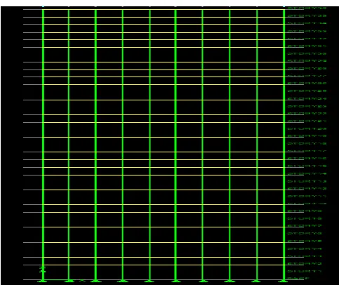
Fig -2: Elevation of simple structure
Fig -3: Plan of Diagrid structure
Fig -4: Elevation of Diagrid structure
3. RESULTS
3.1 DISPLACEMENTS OF STOREYS
a. DLLLEQX COMBO FOR BOTH STRUCTURES
Fig -5: Storey Vs storey displacement drift
b. DLLLWLX COMBO FOR BOTH STRUCTURES
[image:3.595.320.551.97.291.2] [image:3.595.40.282.323.526.2] [image:3.595.324.540.368.544.2]© 2017, IRJET | Impact Factor value: 5.181 | ISO 9001:2008 Certified Journal
| Page 1344
3.2 SHEAR FORCES OF STOREYS
a. DLLLEQX COMBO FOR BOTH STRUCTURES
Fig -7: Storey Vs Storey shear
b. DLLLWLX COMBO FOR BOTH STRUCTURES
Fig -8: Storey Vs Storey shear
3.3 MODE AND TIME PERIOD
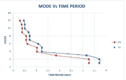
Fig -9: Mode Vs Time period for different modes
4. CONCLUSION
1. From the graphs of storey vs storey displacement we can conclude that for all the load combinations the top story displacement in case of diagrid structure is less than conventional structure. This is because the diagrid structures are stiffer and hence they displace less as compared to conventional ones.
2. For all the earthquake load combinations we can see from the graph plotted for storey vs storey shear that the storey shear in case of diagrid structure is more as compared to simple R.C.C. structure.
3. For all the load combinations we can see from the graph plotted for storey vs storey drift that the storey drift in case of diagrid structure is lesser as compared to simple R.C.C. structure.
4. From the graph of mode vs time period we can see that for all the 12 modes the time period of oscillation for diagrid structure is much less as compared conventional structure. This is because as the diagrid structure is stiffer than the conventional structure, its flexibility is less and hence it has lesser time period.
5.
[image:4.595.50.273.122.273.2]
Fig -10 : Material consumption for both structures
6. From the above bar chart we can see that the quantity of steel required in case of diagrid structure is approximately 37 % less than conventional structure of same plan area whereas the concrete requirement is approximately 3.5 % more than conventional structure. Therefore overall diagrid structure is more economical than conventional structure.
[image:4.595.36.289.287.478.2] [image:4.595.339.572.446.608.2] [image:4.595.37.290.534.694.2]© 2017, IRJET | Impact Factor value: 5.181 | ISO 9001:2008 Certified Journal
| Page 1345
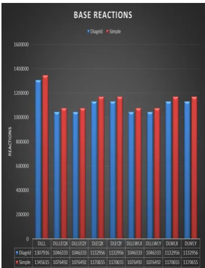
[image:5.595.81.290.155.428.2]combinations the reaction coming on diagrid structure is less than conventional structure and hence the diagrid structure is much more stable than the conventional structure.
Fig -11 : Base reactions for both structures
8. Diagrid structural system provides more flexibility in planning interior space and façade of the building.
9. Generous amount of day lighting, natural air and improved cross air ventilation can be achieved due to minimum provision of interior columns in the plan of structure and thus the optimum usage of natural resources could be achieved.
ACKNOWLEDGEMENTS
I am very much thankful to my guide Prof. Sandeep Sathe for his guidance and also very much thankful to Civil Department, MITCOE for giving such facilities and platform for executing the work.
REFERENCES
[1] Kyoung Sun Moon, Jerome J Connor, John E Fernandez,
“Diagrid Structural Systems for tall buildings: characteristics and methodology for preliminary design”, Struct. Design Tall Spec. Build. 16(2007), 205– 230
[2] Khusbu Jani and Paresh V.Patel, “Analysis and Design of
Diagrid Structural System for High Rise Steel Buildings”, Proceedia Engineering, 51(2012), 92 – 100.
[3] Kyoung Sun Moon, “Diagrid structures for complex
shaped tall buildings”, Proceedia Engineering, 14(2011), 1343-1350
[4] Harshita Tripathi, Dr. Sarita Singla, “Diagrid Structural
System For R.C.Framed Multistoreyed Buildings”, ISSN 2229-5518 Volume 7, Issue 6, June-2016
[5] Pallavi Bhale, Prof .P.J. Salunke, “Analytical Study And