© 2018, IRJET | Impact Factor value: 6.171 | ISO 9001:2008 Certified Journal | Page 331
ANALYSIS OF BIANGLE SHAPED FOOTING SUBJECTED TO TWO WAY
ECCENTRIC LOADING BY FINITE ELEMENT ANALYSIS
Sharad Chaurasia
1, Dr. Rakesh Kumar
21
PG Student, CED, Maulana Azad National Institute of Technology, Bhopal, India
2Assistant Professor, CED, Maulana Azad National Institute of Technology, Bhopal, India
---***---Abstract -
Footing subjected to eccentric loading along twomutually perpendicular axes is quite a common field problem. Due to this bearing capacity is reduced considerably as the effective size is drastically reduced. A footing may be subjected to one way or two-way eccentricity due to many reasons. In the case of footing subjected to one-way eccentricity the common practice is to match the centre of gravity of column loads to centre of gravity of footing area. Strap footings are also commonly used when the footing is subjected to two-way eccentric load. These footings not only resist the eccentric loading without (negligible) tilt but increase the bearing capacity also. Using the idea of angle-shaped footings and bi-angle shaped footing which was a result from the study of partial confinement, another new idea, has been developed. These footings have shape in the form of one vertically downward projection towards the eccentric side of one adjacent edge. In the present paper Square Angle shaped footing which was the experimental work of Dr. H. K Mahiyar has been analysed and then verified by Finite Element Technique using ANSYS software. Secondly rectangular footings subjected to eccentric loadings have been considered and an analysis has been done by taking different points of eccentricity along with varying projection and sizes of footing. Footing under a point load at some eccentricity along diagonal with one vertically downward footing projections of equal length along one adjacent side towards the eccentricity have been analysed. To get the zero-tilt condition of the footing for the eccentric load, the projection has been given certain ratios with respect to the size of the footing. It has been observed that the equation given by Dr. H K Mahiyar was verified and the position of the zero tilt of rectangular angle shaped footing could be achieved successfully.
Key Words: Biangle shaped footing, eccentric loading, tilt, settlement, ANSYS software.
1. INTRODUCTION
If a foundation is subjected to eccentric inclined loads it becomes important to understand the aspect of foundation design and also the behaviour of surrounding soil. It is important to keep in mind that the foundation design must possess sufficient safety against failure and settlement and the tolerable limit to be kept in mind. The requirements mentioned above are dependent mainly on the bearing capacity and compressibility. It can be said that the criteria of settlement are more critical than the bearing capacity during the design of shallow foundations. The safety of a structure can be ensured by limiting the differential
settlements and the total settlements. For pad or strip foundations the settlement criteria are generally limited to 25mm. In order to avoid tension between soil and foundation and also to have a safe design the criteria of less than footing width (e<B/6) should be followed. The results of the eccentric load are that the footing tends to tilt in the direction of the eccentric load and the pressure below the footing does remain uniform. The amount by which the footing tilts depends upon the eccentric width ratio.
A footing may be subjected to eccentric loading due to any of the following reasons:
1) The centre of gravity of the column and the footing doesn’t coincide with each other. 2) There are axial loads coming on to the footing
along with some moments.
3) Either one or two adjacent sides of the footing are close to the property line.
4) Building is subjected to earthquake or wind force.
The moments along which the corner columns are subjected to are basically along two different planes (i.e. biaxial bending). This biaxial bending develops the eccentricity along two mutually perpendicular directions, also even if the footings are subjected to axial load they may be located near the property line along the two directions this is also another reason of footings being subjected to two-way eccentric loading.
In case of high rise structures, a footing may be subjected to inclined loading, a large amount of wind forces come on these structures and they are also designed to sway under these forces, in such a case the loading which comes on the footing is said to be inclined loading. The inclined load tends to tilt the footing in the direction of the loading.
1.1 Need for Present Investigation
© 2018, IRJET | Impact Factor value: 6.171 | ISO 9001:2008 Certified Journal | Page 332
1.2. Objective of the Study
In the present study the derived equation of no tilt condition (i.e. Eq.1.2) has been verified by taking square footing of different sizes and footing projections of different depths. The material for footing and its projections has been assumed to be reinforced cement concrete. Six sizes of square footing (i.e. B=1.0 m, 1.50 m, 2.0 m, 2.50 m, 3.0 m and 4.0 m) have been considered and four depths of footing projections (i.e. D/B= 0.2, 0.4, 0.6 and 0.8) have been considered for each size. Different loads to have a constant load intensity of 250KN/m2 for different sizes and depths of footing projections have been applied at different e/R values in accordance to Eq1.2 and the displacements along 3 mutually perpendicular axes have been noted at different point on footing and its projections.
Similarly, rectangular footings of aspect ratio 1:1.5 and 1:2 have been studied, the depths of both footing projections have been kept equal. The position of zero tilt for rectangular footing has been obtained by considering different e/R and different D/B or D/L values. For the analysis purpose the readymade software i.e. ANSYS 12 has been employed.
It has been concluded that the earlier equation derived holds good even for different sizes of square footing and it has also been found that the equation remains the same even by changing the grades of concrete.
2. Methodology
The tilt of a footing due to eccentricity was reduced to zero by the introduction of Angle Shaped Footing by Mahiya H K (2000).
When a vertical projection is provided in a footing in such a way that it is into the soil on one side of the footing (the side in which the eccentric load is coming) is called an Angle Shaped Footing. The particles of the soil which are near the footing are prevented from moving laterally thus cause the footing to tilt in the direction opposite to the eccentric load. Thus, if a downward projection is provided such that it can encounter the eccentric load, the tilt of the footing can be reduced to zero.
By varying two dimensionless parameters namely ex/B and D/B he developed the equation of the following type, which is found to be independent of the material of footing and the properties of the underlying sandy soil i.e.
D/B = 85.77(
e
x/B)3 - 8.95(e
x /B)2+ 3.42(e
x /B) 0.0012….(1.1)Where,
B = width of footing;
D = depth of footing projection;
e
x = eccentricity along x-axis;The idea of Angle Shaped Footing was again extended to the two-way eccentric loading in the form of Bi-angle Shaped Footing by Mahiyar H.K. (2000) in which he considered two vertical projections along the two adjacent edges of footing which remains embedded in the soil.
When a footing with two vertical projections is subjected to two ways eccentric loading and such that the projections are an integral part of footing it is called Biangle Shaped Footing. The footing projections prevent the tilt in the direction in which the footing has the tendency to tilt reducing the tilt to zero.
Construction of vertical projections at the base of the footing, confining the underlying soil, generates a soil resistance on projection sides that helps the footing to resist sliding. The equation for no tilt condition developed by Mahiyar H K (2000) is of following type:
D/B=68.32(e/R)2-0.172(e/R)+0.00036………(1.2)
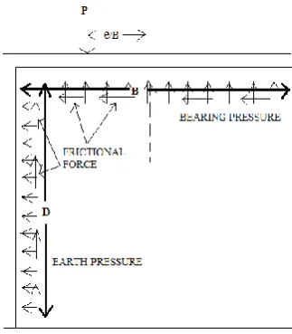
[image:2.595.375.545.343.494.2]Where, D=depth of the projections, B=breadth of the footing, e=diagonal eccentricity, R=diagonal length
Figure 1 3D diagram of biangle shaped footing subjected to two way eccentric and vertical loading
[image:2.595.355.517.538.723.2]© 2018, IRJET | Impact Factor value: 6.171 | ISO 9001:2008 Certified Journal | Page 333 Figure 3 Cross section Y-Y biangle shaped footing
subjected to two ways eccentric and vertical loading
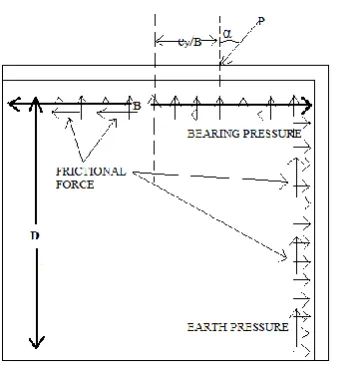
The concept of footing in which the footing projection is at right angle to footing and such footings subjected to eccentric vertical load was extended to footings under eccentric and inclined loading by rotating the footing projection at an angle β with vertical in clock wise direction. Thus, taking two same dimensionless parameters i.e. ex/B and D/B and introducing two other variables namely the Angle of Footing Projection β and the Load Inclination α, Mahiyar H K (2009) and Joshi D P developed the charts for zero tilt and negligible horizontal displacement for such cases.
The biangle shaped footing is a modern concept to optimize the geometry of structural element i.e. foundation so that it becomes more useful and economical than its orthodox geometry. The capability of biangle shaped footing to support the structure depends upon various factors. These factors are intensity load, depth of projection and size of footing. The free body diagram of biangle shaped footing shows various forces developed and their nature on it.
The use of biangle shaped footing for the structures can be the solution for many of the civil engineering problems. But to make it safe for using it in the structure, it is necessary to know about the various forces developed in it.
The software ANSYS which is based on Finite Element Technique is used for the purpose of analysis. The Graphic User Interface of any software makes good use of the features available for the development of the computerized model of the actual problem. The three-dimensional model of angle shaped footing and two-dimensional model gives the same results because the forces in the Z direction is negligible, and the problem can be considered as the plane stress problem.
2.1 Modeling in ANSYS
I. Geometry II. Meshing
III. Boundary Conditions IV. Solution Options
V. Calculation of Results VI. Validation of Results
2.2 Objectives
Following are the objectives of the research work presented here-
To study the behavior of bi-angle shaped footing under the eccentric load.
To validate the derived equation of bi-angle shaped footing by applying variable force in accordance with the following equations:
D/B=68.32(e/R)2 - 0.172(e/R) +0.00036
Where,
D=depth of the projection
B=breadth of the footing
e=diagonal eccentricity & R=diagonal length
Keeping the depth of projection
D/B = 0.2, 0.4, 0.6, 0.8
Also, by changing the size of footing as follows;
B = 1.0 m × 1.0 m, 1.5 m × 1.5 m, 2 m × 1.5 m, 2.5 m × 2.5 m, 3.0 m × 3.0 m & 4 m × 4.0 m
• To compare the results with the work done previously, both experimentally as well as on finite element modeling software.
• To find the zero-tilt condition for rectangle footing of aspect ratios 1:2 and 1:1.5.
Figure -4: shows the meshed soil mass in the software ANSYS 12 and the biangle shaped footing subjected to a
[image:3.595.318.551.521.716.2]© 2018, IRJET | Impact Factor value: 6.171 | ISO 9001:2008 Certified Journal | Page 334
3. Result & Analysis
The displacements for various cases of square and rectangular footing have been presented in the graphical form. The top four corners nodes on the footing have been considering for vertically downward settlement.
Graph -1: Vertically Downward Settlements of Biangle Shaped Vs Square Footing of Size vary from 1.0 m X 1.0 m
to 4m X 4m and different D/B ratio For Load Intensity 250kN/m2
Graph -2: e/R Vs Rectangle Footing of Size 1.0 m X 2.0 m for different D/B ratio at Load Intensity 250kN/m2
Graph -3: e/R Vs Rectangle Footing of Size 1.0 m X 1.5 m for different D/B ratio at Load Intensity 250kN/m2
Graph -4: e/R Vs Rectangle Footing of Size 1.0 m X 1.2 m for different D/L ratio at Load Intensity 250kN/m2
Graph -5: e/R Vs Rectangle Footing of Size 1.0 m X 1.5 m for different D/L ratio at Load Intensity 250kN/m2
The no of cases of square and rectangular footing have been considered. The equation derived earlier for zero tilt condition for biangle shaped square footing was verified using the simulation software ANSYS, so that the research can be utilized on field for the benefit of the common people. Based upon the output of ANSYS and following are the conclusions.
(A) Square Footing
•It has been observed that the zero-tilt condition prevails as per the equation derived earlier.
•By varying the size of square footing, the equation doesn’t change and the settlement at constant load intensity of 250kN/m2 increases linearly at a constant D/B. However, the increase in settlement is not very substantial and it can be considered to be almost constant.
(B) Rectangle Footing
© 2018, IRJET | Impact Factor value: 6.171 | ISO 9001:2008 Certified Journal | Page 335 (i.e. e/R value is a little less the than that for square footing
of same condition)
•The increase in e/R value with increase in D/B or D/L value is not much effective.
•The displacement values along X and Z direction for the entire footing and projection are almost equal and the values are very small which can be neglected. This means that there is no twisting in the footing and projections.
ACKNOWLEDGMENT
We are thankful to Er. Shalem Ernest, Ph.D. scholar NIT Raipur for motivating and encouraging in this research work. We are also thankful to Asst. Prof. Anshuman Nimade for his contribution for the completion of this paper.
REFERENCES
[1]
“Analysis of angle shaped footing under eccentric vertical load “journal of geotechnical and geo-environmental engineering. Vol 126. No.1, p 1151-1156 December 2000.[2] “Angle shaped footing under eccentric vertical load” Indian Geo-Technical Journal Vol.40 No.2 pp-129-134
[3] “Analysis of angle shaped square footings resting on soil under eccentric inclined load” –published in emerging journal on engineering science and technology. Vol 1. No.1, no. 08-jan09 pp-8-15.
[4] “Performance of angle shape footing resting on soil under eccentric inclined load” –published in emerging journal on geotechnical engineering, Vol 14, Band.Fpp 1-10.
[5] “Angle shaped rectangular footing with variable angle of footing projection under eccentric vertical load”- published in emerging journal on geotechnical engineering, Vol 14, Band pp 1-9.
[6] “Effectiveness of angle shaped footings resting on soil under eccentric inclined load” published in international journal of theoretical and applied mechanics ISSN 0973-6085 Vol 4 no.1 pp. 95-105.
[7] “Application of finite element techniques analysis angle shaped footing.”-Published in international journal of theoretical and applied mechanics ISSN 0973-4562 Vol 4 no.6 pp. 1071-1084.
[8] “Moment tilt characteristics of angle shaped footing under eccentric inclined loading”-published in international journal of theoretical and applied mechanics ISSN 0973-4562 Vol 4 no.1 pp. 1085-1092.
[9] Abel, F., J. and Desai, S., C. (1972), “Introduction to the Finite Element Method”, Litton Educational Publishing, Inc., New York.
[10] Atulkar, K., Narendra (2007), “Optimization of angle shaped footing”, M.E. thesis submitted to R.G.P.V., Bhopal.
[11] Czap, Z. (1994), “Finite element analysis of cutting resistance in foundation design", Periodical Polytechnic: Civil Engineering, 38(l), pp 21-28.
[12] Duwasa, Anand (2007), “Experimental study of bi-angle shaped footing subjected to two-way eccentric loading with pile under sand”, M.E. thesis submitted to R.G.P.V., Bhopal.
[13] Kanungo, A. (2004), “Experimental study of angle shaped square footing on cohesive and cohesion less soil under eccentric loading”, M.E. thesis submitted to R.G.P.V., Indore.
[14] Paice, G., M., Griffiths, D., V., Fenton, G., A. (1996), “Finite Element Modeling of Settlements on Spatially Random Soil”, Journal of Geotechnical Engineering, 122 (9), 777-779.
[15] Rajput, D. (2006), “Bi-angle shaped model footing subjected to one-way eccentric load under mixed soil condition”, M.E. thesis submitted to R.G.P.V. Bhopal
[16] Rashidi, M., Gholami, M., (2008), “Modeling of Soil Pressure-Shrinkage Behavior Using Finite Element Method”, World Applied Sciences Journal 3(4) 629-638.
[17] Verma, Narendra (2007), “Experimental study of angle shaped footing subjected to eccentric loading with pile under sand”, M.E. thesis submitted to R.G.P.V., Bhopal.