Maintaining Voltage Stability by Optimal Locating and
Sizing by Combined Evolutionary Algorithm
A. Siva Sankar
Lecturer in Electrical and Electronics Engineering Department of Technical Education, Govt Polytechnic for Women, Kadapa,
Andhra Pradesh, India
K.S.R.Anjaneyulu
Professor of Electrical & Electronics Engineering, Principal JNTU College of
Engineering,
Jawaharlal Nehru Technological University, Anantapur, A.P., India
ABSTRACT
This paper proposes an algorithm for optimal placement of FACTS devices in transmission line to maintain the power system voltage stability and optimal sizing of the FACTS device. The aim of this paper is to improve voltage stability and reduce the total power losses. Here, voltage stability means no variation in the voltages of each bus beyond its boundaries and system stability is the ability of power system to recover the initial steady state after any deviation of the system’s operation. For this work, we presented the combined evolutionary algorithm i.e. Cuckoo Search (CS) and Evolutionary Programming (EP) algorithm to find the optimal location and optimal capacity to be placed at the location for FACTS device. Here, CS is used to find the optimal location of UPFC to be placed in the transmission line and EP algorithm is needed to compute the optimal capacity of corresponding FACTS device at the location. The capacity of the UPFC at that location depends on voltage deviation of the selected bus from slack bus, power loss, voltage instability and the insufficient reactive power in the power system. The presented technique helps in the optimal placement and optimal capacity of the FACTS device to be placed. Thus, the proposed method helps in the improvement of reactive power to meet the voltage stability and the reduction of the total power losses. A simulation on IEEE 30-bus reliability test system (RTS) justifies the reliability of the proposed method for real system applications concerning voltage stability improvement in power system.
Keywords
Flexible AC Transmission Systems (FACTS), Cuckoo Search Algorithm (CS), Evolutionary Programming (EP), Unified Power Flow Conditioner (UPFC).
1.
INTRODUCTION
Power system is a complex network comprising of numerous generators, transmission lines, variety of loads and transformers [1]. The characteristics of the system vary with changes in load and generation schedules [2]. In addition to this, the deregulation of the electric industry has created new technical needs to be satisfied for achieving better control between network interconnections [3]. The complexity of the system poses new challenges to power system stability [4]. Power demand has increased substantially while the expansion of power generation and transmission has been severely limited due to limited resources and environmental restrictions. These reasons impose the stress on transmission networks [5]. The consequence of such a stressed system is that the heavy loaded lines may become a power transfer-limiting factor and sometimes leads to risk of losing stability [6]. Heavily loaded power systems are closer to their stability limits and
voltage collapse blackouts will occur if suitable monitoring and control measures are not taken [7]. The aforesaid disadvantage can be handled by FACTS devices.
FACTS controllers can be employed to enhance power system stability in addition to their main function of power flow control [8]. FACTS devices have the capability of control of various electrical parameters in transmission networks [9]. Controlling the power flows in the network leads to reduce the flow of heavily loaded lines, increased system load ability, less system loss and improved security of the system [10]. FACTS can support the voltages by controlling their parameters including series impedance, shunt impedance, current, and voltage and phase angle [12].
2.
PROPOSED METHODOLOGY
The power system is very large and complex network, which comprises generators, transformers and variety of loads. The load variation and unexpected faults cause the system into the instability operating condition, which can be avoided by satisfying the constraints of the power system, i.e., increase the voltage profile, stable real and reactive power flow and reduced power loss. In this paper Unified Power Flow Controller (UPFC) has been used for the stability improvement.
2.1
UPFC Structure and Load Flow
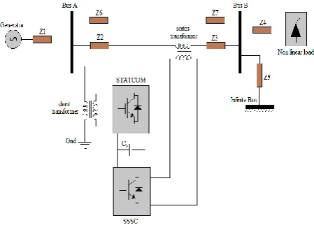
[image:2.595.80.305.409.570.2]Unified Power Flow Controller is a multifunctional flexible ac transmission (FACTS) device with its potential application in power system for the power flow control, voltage control, transient stability improvement and damping of oscillations. In a power system, the power flow for a two-bus system depends on the magnitude of bus voltages, their phase difference and the impedance of the transmission line [16]. UPFC controls the basic parameters of the voltage, impedance or phase angle of a transmission line. It consists of two voltage source converters i.e., STATCOM and SSSC, which are connected with the use of DC link capacitor. SSSC is connected in series with the transmission line and STATCOM connected in parallel with the transmission line. The series and shunt parts of UPFC can control power flow and AC voltage respectively, when a constant voltage is maintained across the DC link capacitor [16]. The proposed UPFC can be used to control the flow of active and reactive power through the line. The proposed UPFC structure is given in the following figure 1.
Figure 1: Structure of the proposed UPFC The active and reactive power flow through the bus A to B at the time t is given by the following equation (1) and (2).
2( ) 2( ) ( ) ( ) ( ) ( )
( ) ( ) ( ) ( )
( ) ( ) ( ) ( )
( )
2
cos(
)
cos(
)
(sin
)
cos
sin
...(1)
t t t t t t
AB A CD AB A CD AB CD B
t t t t
B CD AB CD B AB CD B
t t t t
A B AB AB AB AB
P
t
V
V
G
V V
G
V V
G
b
V V
G
b
( ) ( ) 2( ) ( )
( ) ( ) ( ) ( ) ( ) ( ) ( ) ( )
( )
(
2)
sin(
)
(cos
)
sin
cos
...(2)
t t t t
AB A A AB
t t t t
A CD AB CD A AB CD A
t t t t
A B AB AB AB AB
Q
t
V I
V
b
B
V V
G
b
V V
G
b
Where VA and VB are the voltages of the buses A and B
and VCD is the voltage of the compensating device.
Similarly the real and reactive power flow from the bus B to A is given by the following equation (3) and (4).
2 ( ) ( ) ( ) ( ) ( ) ( ) ( )
( ) ( ) ( ) ( )
( )
cos(
)
sin(
)
cos
sin
...(3)
t t t t t
BA B AB B CD AB CD B
t t
AB CD B
t t t t
A B AB AB AB AB
P
t
V
G
V
V
G
b
G
V
V
G
b
2 ( ) ( ) ( ) ( )
( ) ( )
( ) ( ) ( ) ( )
( )
(
2)
sin(
)
(cos
)
sin
cos
..(4)
t t t t
BA B AB B CD
t t
AB CD B AB CD B
t t t t
A B AB AB AB AB
Q
t
V
b
B
V
V
G
b
V
V
G
b
The real and reactive power injection of the bus A are given by the following equations (5) and (6)
( )
( ) 0
1
( )
(1
)
...(5)
t N t
A GA DA AB
B
P t
P
P
P
( )
( ) 0
1
( )
(1
)
...(6)
t N t
A GA DA AB
B
Q t
Q
Q
Q
Where PDA 0
and QDA 0
are the initial real and reactive power demands. The voltage stability depends on the stability constraints which are given in the following section 2.2.
2.2
Stability Constraints
2.2.1
Calculation of Voltage Stability
The voltage stability constraint plays an important role in the power system stability maintenance. Normally the power system consists of three buses, i.e., slack bus or reference bus, load bus or Q bus and generator bus or P-V bus. The slack bus standard voltage is 1 pu which is assumed as the reference voltage. To find the deviation of the other bus can be calculated by the difference between slack bus voltage and the current bus voltage. The deviation is occurred means corresponding bus stands with instability condition. Voltage stability index of the power system is calculated by the following equation (7).
21
1
( )
(7)
l
VGE D
A
SI
A
V
l
Where
N A A A A E REF DV
jQ
P
Z
V
V
1is the
deviated voltage VA is the A bus voltage PA and QA are the
real and reactive power of bus A, SIVGE(A) is the voltage
stability index of the A bus, VD is the deviated voltage, l is
the number of nodes. The bus voltage lies between the limits, i.e.VAmin ≤ VA ≤ VAmax. The bus voltage stability
index of the bus should be maintained at the range of 1p.u. The bus crossing the limits is identified as the weak bus. The power loss can be described by the following section.
2.2.2
Determination of Power Loss
is satisfied, it should provide the assurance of the power system stability. When the power loss increased, the system violated the stability environment. The aim of the proposed work is to reduce the power loss of the system; it recovers the initial operating condition. The real and reactive power loss is given in the following equation (8).
(8)
GA GA DA LA DA LA
S P
jQ
P
P
j Q
Q
1
*
*
cos(
)
(9)
N
GA DA A B AB AB A B
B
P
P
V
V
Y
1
*
*
sin(
)
(10)
N
GA DA A B AB AB A B
B
Q
Q
V
V
Y
Where PGA and QGA are the real and reactive power
generation, PLA and QLA are the real and reactive power
demand, VA and VB are the voltages of the buses A and B ,
YAB is the bus admittance matrix, αAB is the angle between
the buses A and B, δA and δB are the angle of A and B. The
high power loss buses are identified for the stability maintenance. The real and reactive power flow between the buses is determined in the following section.
2.2.3
Calculation of Real and Reactive Power
Flow
The stability of the power system can be identified by the load flow between the buses, which provides the power balance of the system. In this proposed method N-R method is used for the load flow analysis. The real and reactive power flow equations are given by the following equation (11) and (12).
1
cos
sin
(11)
B
N
A A B AB AB A B AB AB
B
P
V V G
V V B
1
sin
cos
(12)
B N
A A B AB AB A B AB AB B
Q
V V G
V V B
Where A is the sending end bus, B is the receiving end bus, NB is the total number of buses, VBand VB are the
voltage of A and B buses respectively, αAB is the angle
between A and B buses respectively, GAB and BAB are the
conductance and susceptance values respectively. The constraints are determined and then the optimal location is determined using the optimization algorithm. The location where stability constraints are not satisfied is suitable for fixing the UPFC. The capacity of UPFC to improve the voltage profile is determined by the evolutionary programming. The proposed hybrid algorithm is given in the following section 2.3.
2.3
Description of the Proposed Hybrid
Algorithm
The proposed hybrid algorithm is the combination of Swarm algorithm and numerical optimization algorithm. Swarm algorithm is defined as the emergent collective intelligence of groups of simple agents (ant’s colony, artificial bee’s colony, bird flocking and fish schooling)[19]. Numerical optimization algorithm will be used in optimization of certain linear or nonlinear objective functions. Here the cuckoo search technique is used as the optimization algorithm and the numerical
optimization algorithm is used to get the optimal capacity of the UPFC selected.
2.3.1
Cuckoo Search Based Optimal Location
Determination
Based on manner life of Cuckoo bird, one of the newly grown bio-inspired algorithms is the Cuckoo Search (CS). Cuckoos utilize a forceful strategy of reproduction that occupies the female hew nests of other birds to put down their eggs fertilized. Occasionally, the egg of cuckoo in the nest is revealed and the hacked birds throw away or abandon the nest and begin their own offspring somewhere else. Based on the subsequent three idealized rules, the Cuckoo Search was proposed by Yang and Deb 2009 [18] and they are:
a. Every cuckoo lays one egg at a time, and deposits it in a erratically chosen nest;
b. The top nests with high class of eggs (solutions) will take over to the next generations;
c. The number of existing host nests is fixed, and a host can find out an alien egg with a possibility Pa ϵ [0, 1]. In this case, to build an entirely new nest in a new place the host bird can either throw the egg away or discard the nest so as [18]. The CS technique is the well searching technique to find the objective function; the optimization depends on the probability of the objective function. The procedure to find the optimal location is given as follows.
i. Initialize all the input parameters like the bus voltage magnitude, voltage angle, real and reactive power.
ii. Generate the random number population of voltage values.
iii. Using the random number of population determines the objective function, which is given in the equation (1).
1
(13)
N LossA
Fitness
Min
P
Where N is the total number of buses, P Loss is the
power loss.
iv. Determine the better fitness and generate the new solution using the following equation.
1
( )
(14)
t t
i i
X
X
Levy
Where α>0 is the step size, which should be related to the scale of the problem of interest, the
product
means entry-wise multiplications.3
1
,
)
(
t
Levy
Find the fitness of the new solutions and determine the probability of the corresponding solutions.
v. To check the better solutions, if the probability is Pa ϵ [0, 1], the resulting solution is the minimum power loss.
vi. Using the better solution find the maximum power loss location and terminate the process.
programming, depending on the deviation of the UPFC capacity can be determined.
2.3.2
Determination the Optimal UPFC
Capacity Using Evolutionary Programming
The Evolutionary Programming (EP) is the numerical optimization algorithm which is used successfully to solve a great deal of hard combinatorial optimization problems [19]. Here, EP is used to optimize the capacity of the UPFC. The optimal capacity of the UPFC is selected by the voltage stability and power loss of the corresponding bus. The selected capacity must maintain the stability of the system. The instable location of the system, i.e., the bus number, is taken to the input of the EP. The procedure to find the optimal capacity is given as follows.
i. Set the input of the process like optimum location of the bus number.
ii. Generation of the initial populations like the voltage magnitude, voltage angle, real power and reactive power flow between the buses. The initial population of the chromosome is generated in the evolutionary EP and is given by,
]
,
,
[
A1 A2 A3 ANLA
Where
A1
[
V
A1,
V
A2
V
AN]
thevoltage of the bus is,
]
,
[
1 22 N
A A
A
A
V
V
V
is thevoltage angle of the bus,
]
,
[
1 23 N
A A A
A
P
P
P
is the real powerflow of the bus,
A4
[
Q
A1,
Q
A2
Q
AN]
isthe reactive power flow of the bus,
ANLis the chromosome length.iii. Find the UPFC power flow equations, which should satisfy the fitness condition. Using the random number population determine the best capacity.
iv. The stability can be determined by the voltage stability and power loss. Fitness function of the proposed system EP is given in the following equation (15) and (16).
;
1,2,3
(
)
(15)
;
1,2,3
(
)
K A REF
K A REF
if V
V
K
N for not stable
fitness
if V
V
K
N for stable
;
1, 2,3
(
)
(16)
;
1, 2,3
(
)
K LA
K LA
if P
K
N for not stable
fitness
if P
K
N for stable
v. The optimal capacity selection process is determined by the mutation process. For example, cap1, cap2, cap3….. capN are the determined capacity, which fitness is analyzed by equations (3) and (4). If the cap1 and cap3 are satisfied and the cap2 is not satisfied means, it will recover by the new value. It should satisfy the fitness function.
vi. Once the maximum iteration is reached the best optimal capacity among the total values can be selected, other values are not considered.
vii. Terminate the process.
Once the process gets completed, the system is ready to give the optimum capacity of the UPFC. The implementation results of the proposed technique are analyzed in the following section 3.
3.
SIMULATION RESULTS AND
DISCUSSION
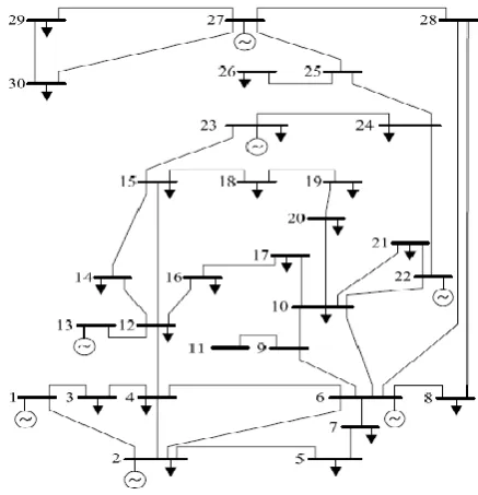
[image:4.595.328.547.322.549.2]The proposed method was implemented in the MATLAB platform. Here, the hybrid method i.e., combination of CS and EP is described for the stability maintaining of the power system. First stage of the hybrid technique is CS algorithm, which optimize the optimal location for fixing the UPFC. The optimal location determination depends on the voltage instability and the maximum power loss of the corresponding bus. The maximum power loss can be minimized by the allocation of UPFC, which has the optimum quantity to recover the stability. The optimum capacity of the UPFC has been selected by using the second stage of the hybrid algorithm i.e., EP. To show the validity of the proposed technique simulation is carried on IEEE 30 bus system. See figure 2 for the test system structure.
Fig 2. IEEE 30 bus system test structure
Table 1. Voltage stability using the proposed method
Bus No
Normal Bus voltage without UPFC
Bus voltages with proposed method after connecting UPFC
Bottom optimal
line 2 - 5
optimal line 5 - 7
optimal line 12 - 15
optimal line 15 -23 1 1.06 0.9959 1.0458 1.0118 1.0172
2 1.033 1.0166 0.99856 1.0185 1.0413
3 1.0228 1.0194 1.0334 0.99328 1.0249
4 1.0135 1.0214 1.0041 0.98997 1.0451
5 1.0044 1.0044 1.0183 1.0214 1.0164
7 0.9999 1.0092 1.0535 1.0168 1.0223
8 1.0103 1.0543 0.99434 0.99227 1.0266
9 1.0423 1.0273 1.0333 1.0007 1.0496
10 1.0352 1.058 1.002 1.0212 1.0051
11 1.0661 1.0368 0.99647 0.99878 1.0227
12 1.0568 1.0052 1.0018 1.0034 0.99471
13 1.071 1.0089 0.99937 1.0416 1.039
14 1.0408 1.0296 1.0322 0.99571 1.0073
15 1.0347 1.006 0.99233 0.99775 0.99303
16 1.0403 1.0518 1.0058 1.0528 1.0229
17 1.0313 1.0028 0.99746 0.9995 1.0427
18 1.0226 1.003 1.022 1.0301 1.0041
19 1.0187 1.0078 1.0339 1.0204 0.99761
20 1.022 1.0167 1.0283 1.0331 1.0052
21 1.0216 0.99366 1.0027 1.0482 1.0242
22 1.03 1.0135 1.0281 1.0143 1.0226
23 1.0218 1.0125 1.0184 1.0018 1.0047
24 1.0154 1.0247 0.99477 1.0128 1.0142
25 1.0068 0.98958 0.98989 1.0233 01.0171
26 0.9889 0.99257 1.0427 1.0257 1.0165
27 1.01 1.0131 1.002 1.031 0.99259
28 1.0094 0.99608 0.99133 1.0148 1.0405
29 0.9899 1.0209 1.0159 1.0071 1.0472
[image:5.595.332.541.68.257.2] [image:5.595.331.539.283.467.2]30 0.9782 0.99531 1.0556 1.0197 0.99463
[image:5.595.90.530.527.658.2]Fig 3: Voltage Stability with/ without UPFC for line 2-5
Fig 4: Voltage Stability with/ without UPFC for line 5-7
Table 2:Power flows and capacity of UPFC for a particular location
Line
Without UPFC With UPFC
Power loss before connecting UPFC
Power loss after connecting UPFC
UPFC Rating (MVA) P(MW) Q(Mvar) P(MW) Q(Mvar)
2-5 72.799 2.549 36.893 -19.069 10.6215 MW 9.53 MW 77.593
5-7 23.748 13.826 15.790 68.766 10.5462 MW 6.2074 MW 25.975
12-15 19.707 8.007 14.250 31.253 10.6221 MW 8.3732 MW 19.811
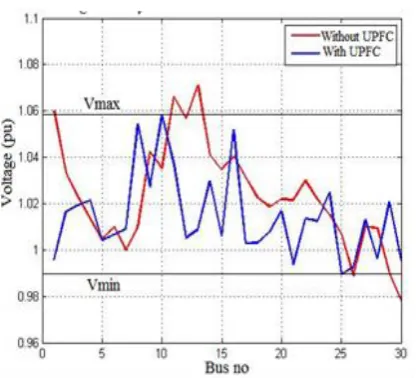
Fig 5: Voltage Stability with/ without UPFC for line 12-15
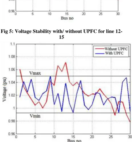
Fig 6: Voltage Stability with/ without UPFC for line 15-23
The table 1 shows the voltage stability analysis of the proposed system, which illustrates the voltage profile of the IEEE 30 bus system under various considerations. The power flows between the buses and capacity of UPFC for a particular location are given in the table 2, which illustrates the normal real and reactive power flows with or without connecting UPFC. The figure 2 shows the voltage stability analysis with and without connecting the UPFC for line 2 -5, in which the voltage level is enhanced by connecting the UPFC. The voltage stability analysis of the lines 5 -7, 12 -15 and 15-23 is illustrated in the figures 4, 5 and 6 respectively. The table 2 shows maximized power loss of the system is 10.5462 MW and it could be minimized at the level 6.2074 MW using UPFC in the line 5-7. The results show that the voltage stability of the power system has been maintained by the proposed method.
4.
CONCLUSION
In this paper the hybrid Evolutionary algorithm i.e. Cuckoo Search (CS) and Evolutionary Programming (EP) algorithm is presented for optimally placing UPFC in transmission line to maintain the voltage stability. Simulations were performed on IEEE 30 bus system using MATLAB platform. In this proposed system CS was used to find the optimal location of UPFC to be placed in the
optimal capacity of corresponding FACTS device at the location. The optimal location for connecting UPFC, the corresponding improvements in the voltage profile and the power loss minimization could be obtained. The results have proved that the proposed technique is a well improved technique to maintain the voltage stability, which is competent over the other techniques.
5.
REFERENCES
[1] D Murali, M Rajaram and N Reka, “Comparison of FACTS Devices for Power System Stability Enhancement”, International Journal of Computer Applications, Vol.8, No.4, pp.30-35, October 2010.
[2] S Sowjanya and J Srinivasarao, “Design of FACTS Device for The Improvement of Power System Stability using Mathematical Matching Controller”, Journal of Electrical and Electronics Engineering, Vol.1, No.3, pp.07-11, 2012.
[3] K Ravi, M Rajaram and J Belwin Edward, “Hybrid Particle Swarm Optimization Technique for Optimal Location of FACTS devices using Optimal Power Flow”, European Journal of Scientific Research, Vol.53, No.1, pp.142-153, 2011.
[4] Sanjiv Kumar and Narendra Kumar, “Effectiveness of FACTS Devices for Power System Stability Enhancement”, International Journal of Advances in Engineering Sciences, Vol.1, No.2, pp.1-4, 2011.
[5] Alok Kumar Mohanty and Amar Kumar Barik, “ Power System Stability Improvement Using FACTS Devices”, International Journal of Modern Engineering Research, Vol.1, No.2, pp.666-672, 2011.
[6] Rahul Somalwar and Manish Khemariya, “A Review of Enhancement of Transient Stability by FACTS Devices”, International Journal of Emerging Technologies in Sciences and Engineering, Vol.5, No.3, pp.72-72, 2012.
[7] A Parizad, A Khazali and M Kalantar, “Application of HSA and GA in Optimal Placement of FACTS Devices Considering Voltage Stability and Losses”, World Academy of Science, Engineering and Technology-32, pp.738-744, 2009.
[8] T A Ramesh Kumaar and I A Chidambaram, “Power System Security Enhancement using FACTS devices in a Power System Network with Voltage Dependent Loads and ZIP Loads”, International Journal of Computer Applications, Vol.45, No.4, pp.26-39, 2012.
[9] S Sutha and N Kamaraj, “Optimal Location of Multi Type Facts Devices for Multiple Contingencies Using Particle Swarm Optimization”, World Academy of Science, Engineering and Technology-22, pp.791-797, 2008.
[10]R Jahani, H Chahkandi Nejad and M Mohammad Abadi, “Optimal Placement of Unified Power Flow Controllers in Electrical Power Systems for Maximize the Loadability of Transmission Lines Using Chaotic Optimization Algorithm”, Australian Journal of Basic and Applied Sciences: 5(10), pp.1538-1543, 2011.
and Applications with workshop of ICEEA, Vol.21, pp.242-248, 2011.
[12]Jigar S Sarda, Manish J Chauhan, Viren B Pandya and Dhaval G Patel, “Optimal Location Of Multi-Types Of FACTS Devices Using Genetic Algorithm”, International Journal of Research in Computer Science, Vol.2, No.3, pp.11-15, 2012.
[13]R Kalaivani and V Kamaraj, “Application of Hybrid PSOGA for Optimal Location of SVC to Improve Voltage Stability of Power System”, International Journal of Electrical and Electronics Engineering, Vol.1 No.4, pp.31-36, 2012.
[14]G Naveen Kumar, M Surya Kalavathi and R Harini Krishna, “Optimal Placement of SVC and STATCOM for Voltage Stability Enhancement under Contingency Using Cat Swarm Optimization”, International Journal of Advances in Engineering & Technology, Vol.5, No.1, pp.436-447, 2012.
[15]K.R.Sudha and K.Harinadha Reddy, “A Fuzzy Controller for Enhancement of Power System Stability with Facts Device”, Journal of Theoretical & Applied Information Technology, Vol.6, No.4, pp.33-38, 2009.
[16]Arup Ratan Bhowmik and Champa Nandi, “Implementation of Unified Power Flow Controller (UPFC) for Power Quality Improvement in IEEE 14-Bus System”, Int. J. Comp. Tech. Appl,Vol.2, No.6,pp.1889-1896,2011
[17]K.Chandrasekaran and Sishaj P. Simon, “Multi-objective unit commitment problem using Cuckoo search Lagrangian method”, International Journal of Engineering, Science and Technology , Vol. 4, No. 2,pp. 89-105, 2012.
[18]Xin-She Yang and Suash Deb, “Cuckoo Search via Levy Flights”, Proc. of World Congress on Nature & Biologically Inspired Computing, pp. 1-7, 2010.
[19]Raymond Chiong and Ooi Koon Beng, "A comparison between Genetic algorithms and Evolutionary Programming based on Cutting Stock Problem", Engineering Letters, 14:1, 12 Feb. 2007
[20]Er. A.K.Mishra, Dr. M. N. Das, Dr. T. C. Panda “Swarm Intelligence Optimization: Editorial Survey”, International Journal of Emerging Technology and Advanced Engineering, Volume 3, Issue 1, January 2013
A.Siva Sankar received B.Tech degree in Electrical Engineering from Jawaharlal Nehru Technological University, Hyderabad in 1999, and M.Tech degree in Power system from Jawaharlal Nehru Technological University, Anantapur in 2006. Presently he is pursuing Ph.D. degree from J.N.T.U. University, Anantapur. Currently he is working as Lecturer in Electrical and Electronics Engineering, Govt Polytechnic for Women, Kadapa under Department of technical education, A.P, Hyderabad, India. His research interests include Power system stability and FACTS.