Buckling behaviour of slender structural elements under
interactive axial static and cyclic loading.
HIRST, Paul B.
Available from Sheffield Hallam University Research Archive (SHURA) at:
http://shura.shu.ac.uk/19797/
This document is the author deposited version. You are advised to consult the
publisher's version if you wish to cite from it.
Published version
HIRST, Paul B. (1987). Buckling behaviour of slender structural elements under
interactive axial static and cyclic loading. Doctoral, Sheffield Hallam University
(United Kingdom)..
Copyright and re-use policy
i U . S A K I
PO N D STREET SH E FFIELD S I 1W B
100217444 9
fall
TELEPEN
llllllllllll
Sheffield City Polytechnic Library
ProQuest Number: 10697099
All rights reserved
INFORMATION TO ALL USERS
The qua lity of this reproduction is d e p e n d e n t upon the qua lity of the copy subm itted.
In the unlikely e v e n t that the author did not send a c o m p le te m anuscript
and there are missing pages, these will be noted. Also, if m aterial had to be rem oved,
a n o te will in d ica te the deletion.
uest
ProQuest 10697099
Published by ProQuest LLC(2017). C o pyright of the Dissertation is held by the Author.
All rights reserved.
This work is protected against unauthorized copying under Title 17, United States C o d e
M icroform Edition © ProQuest LLC.
ProQuest LLC.
789 East Eisenhower Parkway
P.O. Box 1346
BUCKLING BEHAVIOUR OF SLENDER STRUCTURAL ELEMENTS
UNDER INTERACTIVE AXIAL STATIC AND CYCLIC LOADING
PAUL BRENDAN HIRST BSc
A thesis submitted to the Council for National Academic Awards
in partial fulfilment of the requirements for the degree of
Doctor of Philosophy
Sponsoring Establishment
SHEFFIELD CITY POLYTECHNIC
Department of Civil Engineering
Collaborating Establishment
University of Surrey
6 3 . V
n u t
CONTENTS
Advanced Studies Undertaken (v)
List of Tables (vi)
List of Figures (viii)
List of Plates (xiii)
Acknowledgements (xiv)
Abstract (xv)
CHAPTER 1 INITIAL CONSIDERATIONS 1
1.1 Introduction 1
1.2 Basic Structural Instability 3
1.3 Strut Buckling - Historical Resume 13
1.4 Basic Theoretical Modelling 16
1.5 Experimental Considerations 20
1.6 Digital Computer Incorporation 24
1.7 Summary 25
CHAPTER 2 THE ESTABLISHMENT OF A LARGE SCALE
STRUT TESTING SYSTEM 27
2.1 Introduction 27
2.2 Initial Schenck Configuration 28
2.3 Schenck Enhancement - Peripheral Hardware 31
2.3.1 Strut Facility 31
2.3.2 Stub Facility 34
2.3.3 Cyclic Testing Aspects 36
2.3.4 Out-of-Straightness Monitoring 38
2.4 Schenck Enhancement
Digital Computer Incorporation 40
2.5 Preliminary Tests 47
2.5.1 Static Strut Tests 47
2.5.2 Stub Tests 49
2.5.3 Cyclic Strut Tests 51
2.5.4 Resume 53
2.6 Tensile Testing Facility 54
2.7 Ancillary Features 56
2.8 Summary 57
CHAPTER 3 EXPERIMENTAL PROGRAMME 60
3.1 Introduction 60
3.2 Specimen Definition 62
3.2.1 Configuration 62
3.2.2 Reference System 64
3.2.3 Metrology Aspects 64
3.3 Testing Procedures 73
3.3.1 Stub Tests 73
3.3.2 Stub Tests - Cyclic 77
3.3.3 Tensile Tests 77
3.3.4 Strut Tests - Imperfection Monitoring 78
3.3.5 Strut Tests. - Static 82
3.3.6 Strut Tests - Cyclic 85
3.4 Constitutive Behaviour - Results 87
3.4.1 Stub Tests 87
3.4.2 Tensile Tests 90
3.5 Imperfection Assessment Results 93
3.5.2 Load Eccentricity 100
3.6 Static Strut Testing - Results 101
3.6.1 Parametric Response 101
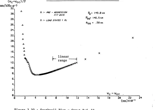
3.6.2 Semi-Empirical Analyses - Southwell
and Lundquist Plots 113
3.7 Cyclic Strut Testing - Results 119
3.7.1 Pseudo-Static Parametric Response 119
3.7.2 Time-Dependent Parametric Response 140
3.7.3 Semi-Empirical Analyses - Southwell
and Lundquist Plots 147
3.8 Additional Strut Tests 156
3.8.1 Comments 156
3.8.2 Cyclic Stub Tests 156
3.8.3 Synthetically Curved Struts 158
3.8.4 Re-Tested Struts 160
3.9 Summary 163
CHAPTER 4 THEORETICAL STUDY 165
4.1 Introduction 165
4.2 Formal Static Moment-Thrust-Curvature
Constitutive Relationships 167
4.3 Novel Constitutive Modelling 172
4.4 Spring-Link Strut Model 175
4.5 Analytical Virtual Work Formulation 179
4.6 Application and Solution Procedures 181
4.6.1 Static Studies 181
4.6.2 Cyclic Studies 181
4.6.3 Non-Linear Solution Routine 184
4.6.4 Static Strut Analysis , Am =l 185
4.7 Case Studies; Static Analyses 187
4.8 Case Studies; Cyclic Analyses
(Pseudo-Static Modelling) 190
4.9 End-Shortening Conditions 206
4.10 Summary 210
CHAPTER 5 DISCUSSION 213
5.1 Introduction 213
5.2 Static-Cyclic Correlation 216
5.2.1 Experimental Considerations; Data Control 216
5.2.2 Pseudo-Static Modelling 229
5.3 Design Implications 237
5.4 Summary 241
CHAPTER 6 CONCLUSIONS 244
6.1 Primary Assessments 244
6.2 Associated Factors 245
6.3 Suggestions for Further Work 247
CHAPTER 7 APPENDICES
I Publications A1
II Typical Numerical Output A36
III Typical x,y/t Output A39
IV List of Computer Programmes A42
V Sample Computer Programme A44
VI Nomenclature A76
ADVANCED STUDIES UNDERTAKEN
1981
27-29 January
1981
Autumn Term
1982
Spring Term
Dynamic Analysis of Offshore Structures
Course
Computational Mechanics Centre, Southampton
Fortran Programming Course
Computer Services
Sheffield City Polytechnic
Computing short courses ( including computer
graphics and microcomputing)
Computer Services
Sheffield City Polytechnic
LIST OF TABLES
Table Title Page
2.1 Preliminary Static Strut Test Results 50
2.2 Preliminary Stub Test Results 52
2.3 Preliminary Cyclic Strut Test Results 52
2.4 Error Analysis 58
3.1 Sample Outer Diameter and Wall Thickness
Measurements 67
3.2 Sample Data for Ovality and Eccentricity
of Loading Assessment 71
3.3 Sample Cross-Sectional Area Measurements 72
3.4 Sample Stub Test Data 88
3.5 Tensile Test Data 92
3.6 Sample (Pin-Ended) Out-of-Straightness Values 94
3.7 Sample (Pin-Ended) Out-of-Straightness Angular
Displacement Values 95
3.8 Pinned-Encastre Mode Correlation 95
3.9 Sample Experimental Static Strut Data 109
3.10 Sample Southwell and Lundquist Plot Data 116
3.11 Cyclic Experimental Data 121
3.12 Primary Experimental Data 124
3.13 Supporting Experimental Data 127
3.14 Quasi-Cyclic Struts - Southwell and Lundquist
Plot Data 152
3.15 Southwell and Lundquist Plot Data 153
Table Title Page
3.17 Synthetically Deformed Strut Test Data
3.18 Retested Strut Test Data
4.1 Sample Static Strut Data - Theoretical
Buckling Load Assessment
4.2 Sample Quasi-Cyclic Strut Data - Theoretical
Buckling Load Assessment
4.3 Theoretical Buckling Loads for Cyclic and
Corresponding Static Struts
4.4 Post-Cyclic Phase Buckling Loads, Pc ,
Expressed as a Percentage of their Fully
Equivalent Static V a l u e s , Pcs
4.5 Theoretical Fully Equivalent Static and
Cyclic Buckling Displacements
4.6 Average Theoretical Buckling Loads Given as
Percentages of their Corresponding Experimental
Buckling Loads
157
157
189
189
195
204
211
LIST OF FIGURES
Figure Title Page
1.1 Idealised Linear Systems Theory 4
1.2 Quasi-Idealised Buckling Considerations 6
1.3 Initially Curved Strut 9
1.4 Buckling Loci 12
1.5 Quasi-Idealised Spring Link Model 17
1.6 Imperfect Spring Link Model 17
1.7 Model: Action-Response Loci 21
2.1 Computer Control and Monitoring Features 42
2.2 Line Diagram of Enhanced Testing System 48
3.1 Reference System 65
3.2 Outer Diameter and Wall Thickness Measurements 65
3.3 Outer Diameter Histogram 68
3.4 Wall Thickness Histogram 69
3.5 Non-Dimensionalised Cross-Sectional Area Histogram 74
3.6 Out-of-Straightness Monitoring Configuration 81
3.7 Central Monitoring Facility 84
3.8 Stub Loci - Yield and Roundhouse Type 89
3.9 Stub and Tensile Test Loci 89
3.10 Direct Modulus and Yield/Proof Stress Histograms 91
3.11 Out-of-Straightness Components - Strut Ref. 6S 91
3.12 Non-Dimensionalised Maximum Initial Lateral
Displacement Histogram 97
3.13 Imperfection Parameters 98
Figure Title Page
3.15 P vs w c l~w o c l ~ Strut Ref. 12S 102
3.16 P vs Ejj - Strut Ref. 12S 103
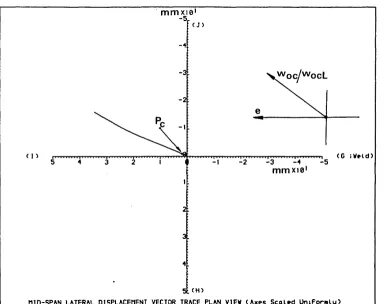
3.17 Vector Trace (P<PC ) - Strut Ref. 12S 103
3.18 Vector Trace - Strut Ref. 12S 104
3.19 P vs u - Strut Ref. 20S 104
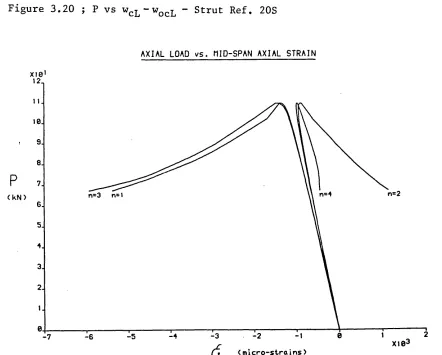
3.20 P vs wcL“wocL “ Strut Ref. 20S 105
3.21 P vs Ejj - Strut Ref. 20S 105
3.22 Vector Trace (P<PC ) - Strut Ref. 20S 106
3.23 Vector Trace - Strut Ref. 20S 106
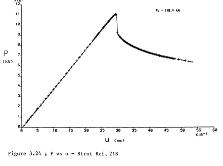
3.24 P vs u - Strut Ref. 21S 108
3.25 P vs w c l“WocL - Strut Ref. 21S 108
3.26 Vector Trace (P<PC ) - Strut Ref. 6S 111
3.27 Vector Trace - Strut Ref. 6S 111
3.28 Pin Ended/Encastre End Condition Correlation 115
3.29 Southwell and Lundquist Plots - Strut Ref. 21S 118
3.30 Southwell Plot - Strut Ref. 5S 118
3.31 Cyclic Strut Studies - Pseudo-Static Considerations 120
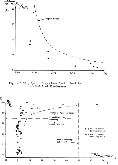
3.32 Cyclic Step/Peak Cyclic Load Ratio vs Modified
Slenderness 128
3.33 Peak Cyclic Load vs Cyclic Step Response 128
3.34 P vs u - Strut Ref. 13C 130
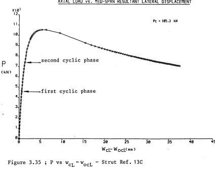
3.35 P vs w c l-w o c l - Strut Ref. 13C 130
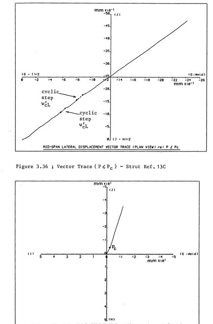
3.36 Vector Trace (P<PC ) - Strut Ref. 13C 131
3.37 Vector Trace - Strut Ref. 13C 131
3.38 P vs u - Strut Ref. 26C 133
3.39 P vs w c l~w o c l - Strut Ref. 26C 133
Figure Title Page
3.40 Vector Trace (P<PC ) - Strut Ref. 26C 134
3.41 Vector Trace - Strut Ref. 26C 134
3.42 P vs u - Strut Ref. 27C 135
3.43 P vs w c l-w o c l - Strut Ref. 27C 135
3.44 Vector Trace (PjvPc ) ~ Strut Ref. 27C 136
3.45 Vector Trace - Strut Ref. 27C 136
3.46 Vector Trace (P_<PC ) - Strut Ref. 19C 137
3.47 P vs u - Strut Ref. 20C 139
3.48 P vs w c l-w o c l ” Strut Ref. 20C 139
3.49 Quasi-Elastic Hysteresis: P vs u Trace
- Strut Ref. 13C 141
3.50 Quasi-Elastic Hysteresis: P vs Trace
- Strut Ref. 13C 141
3.51 Single Band Hysteresis: P vs w c l-w o c l Trace
- Strut Ref. 19C 143
3.52 Multiple Band Hysteresis: P vs w c l_w o c l Trace
- Strut Ref. 21C 143
3.53 Cyclic Creep: P vs w cL-w o c l Trace
- Strut Ref. 26C 144
3.54 Cyclic Creep: P vs w c l-w o c l Trace
- Strut Ref. 27C 145
3.55 P vs u Hysteretic Trace - Strut Ref. 26C 146
3.56 P vs u Hysteretic Trace - Strut Ref. 27C 146
3.57 Cyclic Buckling: P vs u Hysteretic Trace
Figure Title Page
3.58 Cyclic Buckling: P vs w c l~w o c l Hysteretic Trace
- Strut Ref. 20C 149
3.59 Southwell Plot - Strut Ref. 7C 150
3.60 Lundquist Plot - Strut Ref. 7C 150
3.61 Southwell and Lundquist Plots - Strut Ref. 24C 154
3.62 Southwell Plot - Strut Ref. 18C 155
3.63 Lundquist Plot - Strut Ref. 18C 155
3.64 Cyclic Stub Test (Autographic) Output
- Stub Ref. 2D(a) 159
3.65 Cyclic Stub Test: Computer Graphic Output
- Stub Ref. 2D(a) '159
3.66 P vs w cL-w o c l - Strut Ref. 32(a) 161
3.67 Vector Trace (P<PC ) - Strut Ref. 32(a) 161
3.68 P vs wcL-wocL - Strut Ref. 1R 162
3.69 Schedule of Tests 164
4.1 Three Phase Constitutive Topology 168
4.2 Formal M-P-V Contours 171
4.3 Formal M-P-V and Curve Fit Contours 174
4.4. Typical Spring-Link Configuration 176
4.5 Theoretical Model 177
4.6 Quasi-Idealised and Imperfection Buckling
Loci : Xm = 1 186
4.7 Case Study - Strut Ref. 18S 188
4.8 Case Study - Strut Ref. 21S 188
4.9 Case Study - Strut Ref. 3C 192
4.10 Case Study - Strut Ref. 7C 192
Figure 4.11 4.12 4.13 4.14 4.15 4.16 4.17 4.18 4.19 4.20 5.1 5.2 5.3 5.4 5.5 5.6 5.7 5.8 5.9
Title Page
Case Study - Strut Ref. 3C 193
Case Study - Strut Ref. 18C 197
Case Study - Strut Ref. 19C 198
Case Study - Strut Ref. 21C 199
Case Study - Strut Ref. 22C 199
Case Study - Strut Ref. 26C 200
Case Study - Strut Ref. 27C 201
Pseudo-Static Model Characteristics 201
P vs u-u0 Case Study - Strut Ref. 19S 209
P vs u-u0 Case Study - Strut Ref. 20S 209
Normalised Experimental Buckling Loads vs A m 222
Non-Dimensionalised [Pe ] Experimental Buckling
Loads vs
A m
223Non-Dimensionalised [Pp] Experimental Buckling
Loads vs
A m
224Normalised Theoretical Buckling Loads Based on
Direct w oc Values vs X m 232
Normalised Theoretical Buckling Loads Based on
Interpolated woc Values vs A m 233
Normalised Theoretical Buckling Loads Based on
Southwell a os Values vs
Am
234Normalised Theoretical Buckling Loads Based on
Lundquist a0j Values vs
Am
235Experimental Imperfection Data vs Am 239
LIST OF PLATES
Plate Title Page
1 Initial Schenck Configuration 30
2 Load Cell and Collett Assembly 30
3 Strut Test Rig - Transducer Monitoring Network 35
4 Stub Test Rig 37
5 Cyclic Stub Test Rig 37
6 Out-Of-Straightness Monitoring Rig-Base Assembly 39
7 Digital Computer Annexe 39
8 Enhanced Schenck Configuration 46
9 Avery - Tensile Testing Rig 55
10 Stub Specimens 76
11 Tensile Test Specimen 76
12 Ruptured Tensile Test Specimen 79
13 Buckled Strut Specimen (partial recovery) 79
ACKNOWLEDGEMENTS
The author would like to express his appreciation to Dr Neil
Taylor, Director of Studies, and Professor A C Walker, External
Supervisor, for their help and guidance.
This opportunity is also taken to thank Mr P F Lons bo r o u g h ,
Department of Civil Engineering, and Mr M Andersons, Department of
Computer Services, for their assistance with respect to the
testing system enhancement programme.
Material support for the programme was received from the British
Steel Corporation, Tubes Division, Corby. This support is most
ABSTRACT (P B HIRST)
Buckling behaviour of slender structural elements under interactive axial static and cyclic loading
The objective of the research programme has been to investigate the effects of pre-buckling low frequency inelastic cyclic hysteresis upon a range of imperfection sensitive circular hollow
section struts. The programme has involved experimental and
theoretical studies and computer graphics are widely employed
throughout. The subject matter is introduced from a variety of
perspectives, phenomenological, historical, theoretical and
experimental in Chapter 1, together with an appreciation of the role of the digital computer within the research programme. Experimental factors are initially presented in Chapter 2 whilst the formal testing programme is described in Chapter 3. Original findings are definitively set out in Sections 3.3 and 3.7 wherein
the concept of the 'cyclic s t e p 1 is first introduced, the
remaining sections in the chapter providing the necessary supporting data.
Theoretical studies are reported in Chapter 4 with the novel moment-thrust-curvature modelling described in Sections 4.2 and
4.3 being of central importance. This modelling enables the
formulation of a predictive cyclic strut system effectively requiring of the end user the solution of only a pair of simultaneous equations and yet capable of providing data trends consistent with the experimental findings.
Design interpretation together with an overview of the
experimental and theoretical studies and their interrelationship
are set out in Chapter 5. A practical design procedure oriented
about the effect of a pre-buckling cyclic action phase upon
otherwise static strut performance is delineated and an
appropriate design chart is provided.
Conclusions are drawn with respect to the primary research findings in Chapter 6 wherein suggestions are also made regarding possible further studies. An Appendix is included providing the bibliography, nomenclature and respective published work; selected supporting documentation is also presented.
CHAPTER 1
INITIAL CONSIDERATIONS
1.1 INTRODUCTION
Basic static structural analysis employs linear systems theory
which prescribes the deformations to be indefinitely small and the
constitutive properties to be of linear form. However, current
structural design practice is increasingly concerned with the
limit state concept(l) whereby these conditions, particularly the
latter, are subject to revision. Consequently, inelastic
behaviour is of notable interest in bridging between linear
(elastic) and limit (plastic) states. Further, current trends are
towards the employment of slender structural elements, with
emphasis on economic strength-to-weight ratios. This, in turn,
leads to increased importance being attached to stability
considerations which necessarily involve some measure of regard
being given to finite deformations and, crucially, incorporation
of initial imperfection e f f e c t s ^ ) .
Accepting that no service load is truly static(3), an(j given that
there exists a wide range of dynamic configurations, then the
incorporation of dynamic action in nominally static analyses also
requires careful consideration. Severe dynamic action generates
inertial f o r c e s ^ ^ whilst r e s o n a n c e ^ , a singular phenomenon
involving the structure’s natural frequency, is of major
Given the prevention of rigid body motion in static systems, then
essentially static studies which involve some dynamic modelling
are primarily concerned with vibration or cyclic considerations.
Vibrations can be of free or forced excitation forms(6).
Regarding free vibration modes, which relate to impulse or
transient disturbing forces, the presence of damping effects
generally assures a diminishing dynamic response. Conversely,
forced vibration involves continually applied action, generally
cyclic in nature, in which the vibration profiles may be of known,
that is deterministic, configuration or otherwise^) . For low
frequency action, inertial effects are miniraal(^), permitting
some correlation between vibrational effects and static studies
involving incremental plasticity shakedown and alternating
p l a s t i c i t y ^ »10). Fatigue failure must be considered, of course,
although its importance diminishes in cases involving relatively
few cycles (^10^) and the absence of net tension.
Given the foregoing and the recommendations of recent studies
delineating research n e e d s ( ^ » 1 2 ) # present work relates to the
effects of pre-buckling low frequency inelastic cyclic hysteresis
upon a range of imperfection-sensitive circular hollow section
(CHS) struts. Whilst there exists substantial data relating to
the effects of fully reversed cyclic loading upon axially loaded
structural elements(13-21)# little investigation appears to have
been undertaken with respect to the effect of a pre-buckling
cyclic loading phase upon the otherwise static strut buckling
performance^^)
# This would seem somewhat arbitrary given theimportance of imperfections upon strut behaviour and the
possibility of interaction between inelastic hysteresis and
imperfection sensitivity. Accordingly, amplification of the
effects of any initial imperfection due to pre-buckling cyclic
action is considered together with its concomitant effects upon
load carrying capacity and serviceability.
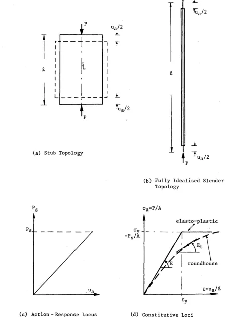
1.2 BASIC STRUCTURAL INSTABILITY
Within the field of elastostaticsC2 3 ) # idealised structural
behaviour can be typified by recourse to the stub and slender
axial compression systems illustrated in Fig 1.1(a) and (b)
respectively. As action parameter P, equivalent to the axial
force in the respective member, is uniformly increased, the
primary response parameter, axial deformation u, represented
herein by the overall axial shortening ua , correspondingly
increases. For systems involving linear constitutive properties
and indefinitely small deformations, ua=PJ,/AE, where £, is the
length, A is the cross-sectional area and E is the direct modulus
of the member. The governing action-response locus is of linear
form as depicted in Fig 1.1(c). All structural response
parameters, including axial stress for example, afford a
corresponding behavioural pattern. The axial or direct stress
generated in the member is given by o^=P/A. System linearity
ceases with the onset of either constitutive non-linearity, that
is the onset of yield in ductile steel structures for example, or
finite deformations which, with regard to the purely axial system
herein, refers to the state at which the induced change in
(a) Stub Topology
ua/2
1
i
r
i
L^ua/2
T
♦
ua/211>
(b) Fully Idealised Slender Topology
aa=
p/
aelasto-plastic
/
roundhouse
e=ufl/£
(c) Action - Response Locus
Figure 1.1 ; Idealised Linear Systems Theory
4
[image:24.615.72.520.42.674.2]system behaviour, of particular relevance to the later work,
finite deformations are typified by slopes exceeding 0.1
radians(24)#
In conjunction with the above, idealised elasto-plastic
constitutive behaviour, as associated with mild steels (eg grade
43), is typified in Fig 1.1(d). Stress-strain behaviour is
therefore linear for cKoy. Actual constitutive loci are derived
from tensile(25) or stub tests(2f>).
*
Consider now the introduction of some relatively small, transient,
lateral interference force Q into each of the foregoing idealised
axial compression systems in the manner denoted in Fig 1.2(a) and
(b), by means of which the systems concerned become only quasi
idealised compression systems. The respective responses of the
stub and slender systems become quite distinct. The behaviour of
the former is effectively unchanged, whilst the latter will
undergo (elastic) instability. The study of instability(27,28)
relates to systems which experience a singular and sudden change
in structural response despite the action parameter being only
gradually and uniformly increased. The fundamental nature of
instability studies can be classified in terms of T h o m ’s
Catastrophe Theory(29)#
Elastic instability can thereby be typified by reference to the
slender compression system depicted in Fig 1.2(b). Noting the
presence of the relatively small, transient force Q, then, as the
CM tj0)
CO CO p~>
d •H
,u u i— CO
i'Oi—i d CO do
d il d o
,H
i o 1—1^ ‘I
1—1o \9iqE}S ajqeijsun •H a o
0)
CO d0
Pi CO a) Pi1
do •H4-J O < 3 a JrJ P-i CM CMh /
O'
i
dJ 00o o
CO 1— 1
•H O
i—i O-i
d o QJ H dJ M I •H CO d d o* 00 d j-i i—i a)d3 u
d d cu PQ i—c
co I
04
--p H
k-CN
d -H K 3
’
1
of ua is again exhibited. However, at some singular or critical
loading state Pe > a sudden change in structural response is
observed; flexural deformation, represented by the central
(mid-span) and maximum transverse deflection parameter wc , is
statically incurred. Further, a flexurally induced axial
end-shortening uf is set up. That is, an apparently axial system is
replaced by a predominantly flexural system at, and beyond, a
singular state associated with compression Pe . The system
typified in Fig 1.2(b) thereby suffers strut buckling action which
onsets at Pe=ir2EA/( &/r )^ (30) with r denoting the minimum radius
of gyration - note Fig 1.2(c). The degree of slenderness,
assessed in terms of the so-called slenderness ratio, &/r, is
clearly of importance with regard to the possible onset of
flexural behaviour. In linearised terms, that is assuming
relatively small deformations, the critical load Pe represents the
limiting load carrying capacity of the member. Experimentation
has shown that such members can sustain loads higher than the
critical or conceptual buckling load Pe , the necessary modelling
requiring a finite deformation study - the ’Elast i c a *(31). The
appropriate behavioural locus is included in Fig 1.2(c). Within
the linear elastic constitutive range, the overall end-shortening
now takes the form
whilst the appropriate maximum stress induced in the member o^j, for P > Pe
(
1
.
1
)
oam
= P/A +Pwc/z
for P > P e(1.2)
where Pwc is the maximum bending moment and Z is the elastic
modulus of the member. For completeness, it is useful to note
that for roundhouse constitutive loci, as associated with
aluminium alloys or mild steel suffering substantial residual
stress effects(32,33)s ^he critical load can be expressed in terms
of a tangent modulus E t or as a reduced derivative(34) - note
Fig 1.1(d).
The foregoing slender strut analysis requires the incorporation of
the ill-defined transient parameter Q; such analyses are thereby
deemed to be quasi-idealised. In practice, physical imperfections
in the structural system are unavoidable and prompt flexural
response, note Eqns (1.1) and (1.2), for P>0; Q conceptually
serves to represent this fact. Physical imperfections can be
classified into three major groups; initial curvature, eccentric
loading and residual stresses(l).
Accordingly, Fig 1.3 illustrates a strut suffering an initial
central deflection, w o c . Assuming a sympathetic initial profile,
w0=w0csin(Trx/iD> then the response, in linearised, terms, is given
by(33)
W
C= W0C(1 - (p/pe))~1
(1
.3)
This behaviour can be typified by imperfection locus 1 depicted in
Fig 1.2(c), where the maximum load converges to the asymptote, Pe .
Similar treatment can be instituted for the other types of
imperfection either by direct analysis or by employing some
effectively equivalent woc in Eqn (l.S)^1). More formally, and
subject to the availability of a suitable yield strength,
employment of a finite deformation study can lead to imperfection
loci of type 2 form as shown in Fig 1.2(c). Loci 1 and 2 both
involve linear elastic constitutive properties being extant
throughout the loading process. The theoretical load carrying
capacity is effectively unaffected by the incorporation of wo c .
Such behaviour is classified as being imperfection insensitive.
However, in practical terms, loci of type 3 as depicted in Fig 1.2
(c) are generally incurred in which the linear elastic limit or
yield stress is breached below P e , with flexurally inelastic
response governing system behaviour where the maximum induced
strain £m>£y. This results in the institution of a maximum load
Pc , which is termed the crippling or buckling load, where Pc<Pe .
The magnitude of Pc is dependent upon the initial imperfections
(eg w o c ) and the yield stress Oy. This form of strut behaviour is
therefore deemed to be inelastically imperfection sensitive(3).
The inclusion of an initially curved strut profile, as illustrated
in Fig 1.3, together with the elastic limit state or first yield
criterion, forms the basis of the Perry formula(35). its
subsequent derivative, employed in the current strut or column
design code of practice BS 5950(36)^ is given by
PePs
ps+(n+i)pe +
/Ps+ (0+1)Pe \?- PePsl *
A2,
2A
\
2A
/ A
J
with Pp and Ps denoting the unfactored design and squash (yield)
loads respectively, where P s=OyA. The empirically based Perry
factor T) is determined by
, i
Tl = 0.001ar (X-Xo) : An=Q.2^TT2Ej (1.5)
where A and Ao denote the slenderness and limiting slenderness
ratios respectively. The Robertson constant ar is assigned
prescribed values according to the cross-sectional configuration
and testifies to the employment of multiple column curves. For
hot rolled and finished CHS struts, which are of primary concern
herein, ar= 2 . The necessarily empirical basis for r| is due to the
essentially statistical nature of practical strut performance,
given both the highly variable and ill-defined form of strut
imperfections.
Fig 1.4 graphically illustrates the appropriate design curve
relating to hot and finished rolled CHS struts, together with the
elastic critical (Euler) and yield loci. The ordinate is
normalised to the squash load Ps , and the abscissa is evaluated in
terms of the modified slenderness ratio A m= A / A i ^ ^ ^ such that
A_ -A/Ai = A/r
= (av /ae)4 = A/r (av /irlE) J
(1.6)
with Al denoting the value of A at the state P s=Pe* This takes
explicit account of the respective constitutive properties and
provides for normalised abscissa values. Also indicated in the
yi
el
d
lo
cu
s
o
CN
■U
■u
o
o
CN
CO
cr>
m ■U
g
•p« R
CO «H *
l_l f) C— '
a.
o
CO
o
o
m m
CN o
•H oo ►J W) C
a 3
PQ
Q) U
3
toO
•H pc-i
slenderness(37)
f with extreme imperfection sensitivity occurringat
A/Al=l-General inelastic strut behaviour is of complex form, and its
treatment is considered at length in the ensuing study. Effort
has been centred about the modified slenderness ratio of unity,
important because of its service practicality and imperfection
sensitivity.
1.3 STRUT BUCKLING - HISTORICAL RESUME
The study of structural systems can be said to begin in earnest
with the Egyptians, surely the first culture to institute
structural forms on a large scale. Developments through Grecian
and Roman studies ebbed with the onset of the Dark Ages and
scientific thought only re-emerged with the Renaissance. Da Vinci
(1452-1519) considered the basic philosophy of the equilibrium of
forces, this being typified in his quote ’Mechanics is the
paradise of mathematical science, because here we come to the
fruits of mathematics'. Amongst his many achievements was his
experimental work on
columns^38)^
Key developments in the seventeenth century may be concisely
represented by the definition of elasticity by Hooke, the
introduction of the principles of 'infinitesimal' calculus by
Leibnitz and Newton, and, of course, Newton's Laws of Motion.
eighteenth century by Euler (1707-1783). Employing the
’infinitesimal
1
calculus he provided an analysis and solution tothe problem of the Elastica, determining the critical load of the
strut under quasi-ideal conditions and subject to linear elastic
constitutive properties. Euler also extended the associated
theory of moraent-curvature and propounded the condition of small
or indefinitely small deformations. The original formal concepts
of first order linear structural theory were introduced by Young
(1773-1829).
The nineteenth century saw a dramatic expansion in the study of
mechanics. Particular interest centred on the work of R a n k i n e ,
who, in 1858, presented a semi-empirical formula that predicted
the crippling state of struts for a wide range of slenderness
ratios. In 1886, the semi-empirical Perry Formula was introduced.
An important step, this formula has formed a basis for column
design through this century.
Robertson published results from an extensive series of steel
column tests in 1925 and, on the basis of these tests, developed
the applicability of Perry's work by proposing an improved value
for the empirical imperfection constant Ti in Perry's formula^-*).
It is to be noted that Perry originally attempted to define,
albeit on an empirical basis, the limiting elastic or first yield
state despite involving the statistically necessary employment of
a load factor approach to design. This useful revision led to the
Perry-Robertson formula being adopted in British practice. In
1929, the Steel Structures Research Committee was set up under one
of the earliest cooperative ventures between British industry and
the Government Department of Science and Industrial R e s e a r c hC3 9 ).
This committee was responsible for introducing the first edition
of BS 449 in 1931. This standard, suitably revised, served until
the publication in 1985 of the current code of practice, which
employs limit state philosophy, BS 5950. Herein, the Perry
formula has been modified in line with a study commissioned by the
European Convention of Constructional Steelwork (ECCS). As a
result, a set of design loci or multiple column-strength curves
are provided which account for the influence of both
cross-sectional geometry and fabrication methods on strut
performance.
The field of inelastic strut buckling, with which the present
study is intimately concerned, has received considerable
attention, the first notable contribution being from Considere in
1889. He indicated the limited applicability of the Euler
analysis, notwithstanding Euler's own intuitive understanding of
the process of inelastic b u c k l i n g ( ^ ) . Supported by experimental
evidence, Considere proposed a modified inelastic Euler
formulation employing a reduced tangent modulus, whose value he
qualified as being intermediate between the direct (Young's) and
tangent moduli. A contemporary study by E n g e s s e r ^ ® ) , whilst
being independent of Considere's contribution, led to the now well
established tangent modulus formula. In 1895, Jasinski brought
Considere's work to the attention of Engesser, who produced a
general reduced tangent modulus approach. In 1910, KArraan
expressions for the reduced tangent moduli of certain standard
structural cross-sections. For the 35 years following Karraan’s
work, controversy surrounded the relative merits of the tangent
and reduced moduli. In 1946, Shanley reconciled this discord with
a rational explanation of the phenomenon in favour of the tangent
modulus approach. A year later he validated this theory by the
analysis of a buckling model that has become eponymous with him(41)
More generally, with the twentieth came the development of a
variety of refined analytical principles, together with an
attendant improvement in the quality of experimental techniques.
Further, the relatively recent advent of the electronic digital
computer has had a dramatic impact upon both analytical and
experimental studies. Modern computers are capable of undertaking
algorithmic computations at phenomenal speed and facilitate the
storage of vast amounts of data in a readily accessible manner.
Since the advent of the first computer, ENSIAC, constructed in
1948 in the USA, engineering analysis and experimental techniques
have in turn developed to take advantage of the digital computer’s
attributes. Given the highly variable, statistical nature of
strut behaviour, these factors are of particular relevance to the
research programme herein discussed.
1.4 BASIC THEORETICAL MODELLING
The representative spring-link model illustrated in Fig 1.5
consists of two rigid and incompressible links, connected by a
centrally located torsional spring of stiffness c - this is a
torsion spring of constant stiffness, c
pin-roller
1 / 2
rigid link
- O G —
U f
/2
Figure 1.5 ; Quasi- Idealised Spring Link Model
— ^ oc
.
±t
constant for linearly constitutive systems. Such models afford
considerable computational amenability. The spring represents the
flexural stiffness of the model in discretised terms. The
response moment M, due to the rotation of the spring, is given by
M=
2
c0
(3
), where0
, the angular link displacement, is the singlekinematic generalised coordinate in this
1
degree-of-freedomsystem. Presently, c = 2 E I / & in accordance with linear elastic
constitutive properties. The spring-link topology is taken to be
initially straight and the attendant analysis is thereby of
quasi-idealised form.
Employing a potential energy approach(35), then, with V denoting
the total potential energy of the system,
V = U - W (1-7)
where U and W are the strain energy and external work functions
respectively. These functions may be derived explicitly in terms
of 0, such that Eqn (1.7) becomes
V = 2c0
2
- P£(1-cos0) (1.8)The condition that V is stationary with respect to 0 for static
equilibrium affords
3V/80 = 4c0 - P£sin0 = 0 (1.9)
Eqn (1.9) can be satisfied either with 0=0 throughout all P, which
forms a flexurally trivial solution, or with
P = 4c0/£sin0 (1*10)
Linearising (1.10), such that 0/sin0=l for small displacements of
0
, affords the critical loadPe = 4c/£ =
8
EI/&2
(
1
.
11
)
with ( 0 jp =0). Accordingly, the quasi-idealised post-buckling
equilibrium path (0>O) is given by
P = Pe0 / sin0
(
1
.
12
)
To establish the nature of the stability of the pre- and
post-buckling loci, the second differential of V with respect to 0 is
noting that maximum V (0
2
V/002
<O) and minimum V (d2
V/(te2
>0) areassociated with unstable, ® | p < P e= ^> anc* stable
0
| Pe^0
>equilibrium respectively.
If an imperfect initial profile is introduced into the former
idealised model as illustrated in Fig 1.6, which is analogous to
the initial curvature profile depicted in Fig 1.3, then V becomes sought(3), whereby
3
2
V/302 = 4c - Pt.cos0 (1.13)2
V = 2c(0-0O ) + P£(cos0-cos0o ) (1.14)
with the equilibrium condition
affording
P = 4c(0-0o )/£sin0 (1.16)
Normalising the loading to its critical value
P/Pe=(0-0o ) / sin0 (1*17)
The locus given by this expression is typically represented by the
imperfection locus illustrated in Fig 1.7; also shown are the
equilibrium loci of the former quasi-idealised analysis.
Spring-link models can provide quantitatively representative data
at low computational cost. This is particularly attractive when
considering more complex inelastic studies and further use of
the spring-link procedure is made in the ensuing theoretical
work.
1.5 EXPERIMENTAL CONSIDERATIONS
Given the previously denoted statistical nature of inelastic strut
performance, then experimentation and empiricism suitably form a
major part of the research programme. Associated with this, the
actual establishment of an accurate large scale testing system
formed an integral part of this programme during the early stages
of the study. Wherever applicable, the necessary compliance with
quasi-idealised locus ( P > P P/P
imperfection locus bifurcation
linearised
1
cf Figure 1.2(c)
4J
British Standards Codes of Practice was ensured; in aspects of the
work not covered by these codes, recommendations from established
literature sources in the field were sought/26).
The experimental system was based on a Schenck 250 tonne
servo-hydraulic stiff column testing machine, possessing over 3m of
available ’daylight1. Stroke or axial displacement control was
employed, providing for static post-buckling path definition.
Cyclic loading capability was made available through an in-board
function generator. CHS steel strut specimens were chosen for
testing purposes. A doubly encastre configuration was considered
to afford the most readily definable form of boundary conditions.
Such configurations afford a common effective length (ft=L/2) in
both the elastic and inelastic material
ranges(42)#
Further,using circular sections should, given a sufficiently large number
of tests, enable a check to be made upon specimen behaviour being
machine independent. That is, the testing machine must not
prejudice the buckling path direction response of the strut, there
being no preferred failure direction (weak axis) resulting from
the geometry of the specimen cross-section. Specimen geometry was
to be based on Am values of about unity, the nominal strut lengths
thereby being between 2.2m and 3.0m.
Material support from the tubes division (Corby) of the British
Steel Corporation led to the provision of 7.5m runs of CHS
electric-weld stretch reduced (EWSR) grade 43C steel; these
sections are stress relieved. Two strut specimens were cut from
each run, one being tested statically, the other being additionally
subjected to cyclic loading phase, thereby affording some degree
of specific static/cyclic strut performance correlation to be
made. Such correspondence is limited by imperfection variability,
however; if the static strut is substantially more imperfect,
correlation of performance is greatly reduced. Consequently, the
large number of tests is again important to statistically provide
for a sufficient degree of correlation. Further, employing
offcuts, a stub t e s t ( 2 6 ) was performed for each strut experiment
undertaken to determine individual specimen constitutive data.
Geometric properties of individual cross-sections were obtained by
recording the relevant measurements. Datum out-of-straightness
measurements were undertaken for each strut prior to actual
testing whilst wall thickness and outer diameter measurements were
employed for ovality and eccentricity of loading as sessments^).
Residual stresses were not explicitly considered in view of their
relative unimportance in the (stress relieved) sections employed
h e r e i n ( 3 5 ) # it is considered that such individual specimen
assessment assists in accurate experimentation.
The Schenck column testing rig was adapted and developed through
the earlier part of the research programme to accommodate the
various types of testing denoted above - static strut, cyclic
strut, stub and initial curvature tests. These developments were
undertaken as part of the general enhancement of the basic testing
system which also involved substantial digital computer provision.
This provision resulted in considerable improvements in system
accuracy, repeatability, control, ’turnround* time and safety;
provided. Various types of computing facility were employed,
depending on the particular requirements involved. This feature
is further discussed in the following section.
Additionally, a supplementary set of tensile tests were carried
out to provide for control on the stub data. These tests were
conducted on an Avery 7110 universal testing machine which
provided for tensile testing to BS 18, Part 4(25).
1.6 DIGITAL COMPUTER INCORPORATION
The experimental phase of the research programme was heavily
influenced by the capabilities of modern computing equipment. The
enhancement of the basic testing facility, whereby diverse
computing systems were interfaced with the Schenck testing
machine, led to improvements in both the quality and production of
experimental data, as denoted in the foregoing section. The
enhanced computer governed testing facility involved micro, mini
and mainframe computers, which were employed in the control, data
monitoring/acquisition and graphical parametric output phases
respectively. The RML380Z microcomputer afforded a '10-b i t ’ DAC
(digital-to-analogue converter) and ADC control unit whilst the
PDP1104(DEC) 16-bit minicomputer provided for high speed accurate
data recording. The IBM4341 mainframe computer supplied both high
resolution graphics software support, together with substantial
and readily accessible data storage facilities.
In addition to interfacing the testing machine with both the micro
and minicomputers, the micro was further interfaced with the mini
and mainframe systems for data transfer purposes.
All drive, monitor and data reduction software was developed
in-house. The BASIC language was used for the smaller computers,
whilst 32/64-bit (per byte) FORTRAN/GINO programming was employed
on the mainframe. The inelastic theoretical studies undertaken in
support of the experimental programme were also implemented on the
mainframe computer. This was considered necessary given the
highly non-linear nature of the expressions involved.
1.7 SUMMARY
The history and nature of strut stability studies have been
identified. The important role of imperfections has been set out,
particularly with regard to struts possessing industrially
relevant slenderness ratios (Am= l)* Attempts to model the complex
inelastic behaviour of these common structural elements should pay
due regard to the requirements of design engineers in practice.
Accordingly, a spring-link modelling procedure which provides for
computationally amenable expressions has been introduced.
Given that the objective of the programme is to determine the
otherwise static behaviour of an inelastically imperfection
sensitive strut subject to a pre-buckling cyclic loading phase,
the need for substantial experimental study has been identified
and discussed. Testing at large scale is demanded if direct
available. Incorporation of the digital computer is to be made
throughout the experimental and theoretical phases of the research
programme. The following chapter sets out the preliminary factors
associated with the experimentation.
CHAPTER 2
THE ESTABLISHMENT OF A LARGE SCALE STRUT TESTING SYSTEM
2.1 INTRODUCTION
Experimentation and empiricism, employing a suitably large number
of tests, are of particular importance with regard to the study of
inelastic strut behaviour(1). This is due to the sensitivity
displayed with respect to the presence of imperfections; the
substantial scatter of the data accompanying strut testing is
well-established^^). Indeed, most recent studies on design
criteria are concerned with the probabilistic basis of the
parameters i n v o l v e d ^34 ) % Accordingly, considerable effort has
been taken in the present programme to ensure high quality
experimentation, with the substantial number of large scale tests
involved being a particular feature.
The fulcrum of the compression testing system employed in the
experimental studies was a +5 volt Schenck 250 tonne column
testing machine. This was employed for the stub and strut
compression tests and initial out-of-straightness monitoring of
the strut specimens. A number of supporting tensile tests were to
be undertaken on an Avery testing machine, with geometric data
obtained from metrology studies completing the experimental
programme.
of the Schenck machine for reasons of accuracy, test
repeatability, fine control, turnround time and safety. Of
particular interest was the incorporation of digital computer
control and monitoring which enabled fully automatic
experimentation and generation of graphical/numerical output data
of high (digital) resolution. Concurrent with this enhancement
was a preliminary series of strut and stub tests undertaken for
purposes of testing system validation; these two activities formed
the first phase of the experimental programme and are discussed in
the following.
2.2 INITIAL SCHENCK CONFIGURATION
The basic Schenck facility essentially consisted of a stiff
mechanical rig, RV-10 servo controller and hydraulic power pack.
The machine cross-head was adjustable on twin threaded columns;
the actuator was located at the base, where the compressive
loading, under axial stroke (displacement) control was applied.
This form of ’loading* control enables identification of the
post-buckling path. Machine ’daylight' provision allowed for over
3m vertical clearance and 0.6m lateral clearance in the plane of
the columns; there was no effective restriction in the third
dimension. The testing machine was of servo-hydraulic form with
the electronic (analogue) commands of the RV-10 servo controller
governing the power pack's delivery of high pressure hydraulic oil
to the actuator. Equivalence of the controller's signal with that
fed back from the Schenck inboard transducer was indicative of the
required incremental axial displacement being achieved. Cyclic
action was provided for by means of a function generator in the
RV-10 controller. Axial load was determined from an inboard
2500kN load cell.
Plate 1 shows the Schenck mechanical rig being employed in its
pre-enhancement or basic form. The specimen involved is a 50mm by
3.2mm SHS - both SHS and CHS specimens were used in the
preliminary tests - with encastre conditions being established
using end caps bolted to the upper and lower plattens, bond
between these caps and the ends of the strut being achieved by the
use of proprietary resin. This arrangement was effective in
restricting rotation of the ends of the strut but inconvenient to
implement. Plate 1 also shows the dial gauges which were
initially employed to measure specimen end-shortening whilst the
centrally mounted strain gauges set a pattern for future tests.
It is to be noted that the deflected shape conforms to that
expected in the post-buckling range. Further discussion on the
preliminary compression tests follows delineation of the actual
testing system enhancement undertaken. It is to be understood
that Sections 2.3 and 2.4 relate to the testing system and
procedures as finally established in the enhanced configuration,
ie the system and procedures employed in the formal testing
programme described in Chapter 3. Section 2.5 deals with tests
undertaken concurrently with this enhancement, these preliminary