International Journal of Emerging Technology and Advanced Engineering
Website: www.ijetae.com (ISSN 2250-2459,ISO 9001:2008 Certified Journal, Volume 3, Issue 7, July 2013)
160
VLSI Architecture to Detect/Correct Errors in Motion
Estimation Using Biresidue Codes
Harsha Priya. M
1, Jyothi Kamatam
2, Y. Aruna Suhasini Devi
31,2
Assistant Professor, 3Associate Professor, Department Of ECE, CMR College Of Engg. & Tech.
Abstract— The motion estimation computing array (MECA) is the most computationally demanding component in a video encoder/decoder. This paper develops a built-in self-detection/correction (BIDC) architecture for motion estimation computing arrays using biresidue codes. The proposed BIDC architecture can be effectively used online to detect and correct any single error of each processing element in an MECA. This architecture is implemented using Xilinx 9.2i ISE. The proposed BIDC architecture performs well in error detection and correction with minor area overhead and timing penalty.
Index Terms— Area overhead, built-in self-correction (BISC), built-in self-detection (BISD), motion estimation computing array (MECA).
I. INTRODUCTION
In more recent years, multimedia technology applications have been becoming more flexible and powerful with the development of semiconductor technology. The latest video standard, H.264/AVD/MPEG_4 part 10 (Advance Video Coding) is regarded as the next generation video compression standard (VCS). For video compression standards, the motion estimation computing array (MECA) is the most computationally demanding component in a video encoder/decoder where about 60-90% of the total of computation time is consumed in motion estimation. Generally, motion estimation computing array (MECA) performs up to 50% of computations in the entire video coding system. Thus, integrating the MECA into a system-on-chip (SOC) design has become increasingly important for video coding applications [1], [5].
Although an advance in VLSI technology allows integration of large number of processing elements (PEs) in an MECA into an SOC, this increases the logic-per-pin ratio, thereby significantly decreasing the efficiency of chip logic testing. For a commercial chip, a video coding system must introduce design for testability (DFT), especially in an MECA. The objective of DFT is to increase the ease with which a device can be tested to guarantee high system reliability. Many DFT approaches have been developed. These approaches can be divided into three categories: ad hoc (problem oriented), structured, and built-in self-test (BIST) [6], [2].
Among these techniques, BIST has an obvious advantage in that expensive test equipment is not needed and tests are low cost. Moreover, BIST can generate test simulations and analyze test responses without outside support, making tests and diagnoses of digital systems quick and effective. However, as the circuit complexity and density increases, the BIST approach must detect the presence of faults and specify their locations for subsequent repair. The extended techniques of BIST are built-in self-diagnosis and built-in self-re-pair (BISR) [7]. Based on the concepts of BIST and biresidue codes, this paper presents a built-in self-detection/correction (BIDC) architecturethat effectively self-detects and self-corrects PE errors in an MECA. Notably, any array-based computing structure, such as the discrete cosine transform (DCT), iterative logic array (ILA), and finite-impulse filter (FIR), is suitable for the proposed method to detect and correct errors based on biresidue codes.
II. ERROR DETECTION/CORRECTION CODES
The use of residue codes to detect error is a useful approach in computer arithmetic. Residue codes are separable arithmetic codes that calculate a residue for data, and then apply this residue to data to detect error. For instance, we assume N denotes an integer, N1 and N2 represent data words, and A is the modulus. A separate residue code of interest is one in which N is coded as a pair (N, N A). Notably, N A is the residue of N modulo A. However, error correction cannot be performed effectively using residue codes. The arithmetic code, namely biresidue codes, can be supported to realize error detection and error correction.
The biresidue codes separate residue coding using two residue detectors with respect to two suitable moduli. Consider integer N coded as a triple (N, N A, N B), where A and B are two relatively prime integers. Let moduli A = 2a - 1and B = 2b – 1 such that GCD(a,b) = 1.The set of all single errors denoted by {e = ±2i , i = 0,1,2…..n-1} will have distinct syndromes with respect to A and B provided n is not greater than ab.
International Journal of Emerging Technology and Advanced Engineering
Website: www.ijetae.com (ISSN 2250-2459,ISO 9001:2008 Certified Journal, Volume 3, Issue 7, July 2013)
161
Moreover, the syndrome for the triple (X,Y,Z) with respect to moduli A and B, denoted as S(X,Y,Z), is a pair (sa, sb) where sa = X-YA and sb = X-Z B. Thus, a triple (X,Y,Z) of integers is a biresidue code word with respect to moduli A and B if and only if its syndrome S(X,Y,Z) with respect to moduli A and B equals zero (sa = 0, sb = =0). In other words, the error in any component is detected and located based on the form of its corresponding syndrome. In accordance with the error detection and error correction concepts in biresidue codes, this paper proposes BIDC architecture to self-detect and self-correct PE errors in an MECA.
III. BIDCARCHITECTURE
The proposed BIDC architecture, adopts the MECA as a CUT [3], that consists of many PEs connected into a 1-D or 2-1-D array for video encoding applications. Generally, a PE is made up of two adders (an 8-bit adder and a 12-bit adder) and an accumulator. The PE in an MECA computes the absolute difference between one pixel of the search area and one pixel of the current macro block. Thus, by utilizing PEs, the sum of absolute differences (SADs) shown in (1) between the current macro block and each search position can be evaluated
Where c(i,j) and r(i,j) are the luminance pixel value of current pixel (Cur.pixel) and reference pixel (Ref.pixel), respectively. The macro block size is N x N. The best motion position of a 4 x 4 block from the previous frame to the current frame can be captured easily using MECA operations in the video encoding system. The output of a specific PEi can be delivered to a detector for detecting errors.
[image:2.595.60.543.586.741.2]Moreover, the selector circuit receives data from a specific PE, and then exports these data to the next specific PEi+1 or syndrome analysis and corrector (SAC) for error correction.
Fig. 1 Architecture of BIDC
The self-detection and self-correction operations (Fig. 1) are described as follows. The input data of Cur.pixel and Ref.pixel for a specific PEi in the MECA are sent to the test code generator (TCG) to generate the corresponding test codes. Then the test codes from the TCG and output data from the specific PEi are detected and verified in detector and selector (DAS) circuits to determine whether the specific PEi has an error. In other words, the self-detection capability uses the detector circuit in DAS. The selector circuit in DAS delivers the error signal to SAC for error correction. Finally, the error correction data from SAC, or error-free data from the selector circuit in DAS, are passed to the next specific PEi+1 for subsequent testing.
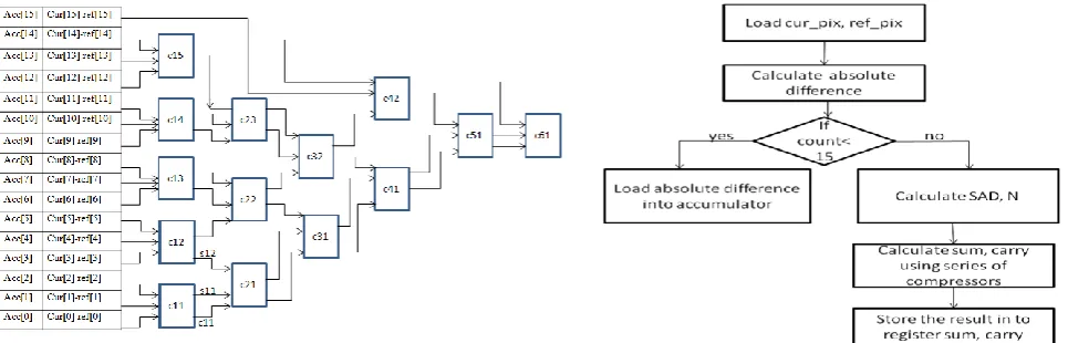
A. Internal structure of processing element
Processing element in motion estimation computes the absolute difference between current pixel and the reference pixel. Compressor is used for calculating sum of absolute value of current pixel and reference pixels to calculate the compressed value of the computation,
International Journal of Emerging Technology and Advanced Engineering
Website: www.ijetae.com (ISSN 2250-2459,ISO 9001:2008 Certified Journal, Volume 3, Issue 7, July 2013)
162
Processing element in motion estimation computes the absolute difference between current pixel and the reference pixel. Compressor is used for calculating sum of absolute value of current pixel and reference pixels to calculate the compressed value of the computation,
B. Fault Model
The single stuck-at (SSA) model is a comprehensive fault model that is required to cover actual failures in the interconnect data bus between PEs. The SSA fault is a well-known structural fault model that assumes faults cause a line in the circuit to behave as if it were permanently at logic “0” [stuck-at 0 (SA0)] or logic “1” [stuck-at 1 (SA1)]. The SSA fault in MECA architecture can result in errors in computed SAD values. This paper refers to this as a distorted computational error; its magnitude is e = SAD’ – SAD, where SAD’ is the computed SAD value with an SSA fault.
C. BIDC Process
Fig. 1.1 shows an example of a specific PEi to describe explicitly the self-detection and self-correction of errors in an MECA using the Proposed BIDC architecture. The TCG circuit uses two coders (coders 1 and 2) to generate test codes.
The following definitions, based on the biresidue codes, are applied to verify the feasibility of the two coders in the TCG.
Definition 1: N1+N2 = N1 + N2 (2)
Definition 2: Let Nj = n1 + n2 + + nj ,then
Nj = n1+ n2 + + nj (3)
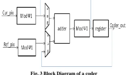
Based on Definitions 1 and 2, the design of the coder
1 (or coder 2) circuit can be realized and shown in Fig. 1.3.
[image:3.595.60.265.559.681.2]Fig. 3 Block Diagram of a coder
D. Detector & Selector
The self-detection operation can be achieved using the DAS circuit. The detector circuit is utilized to compare the outputs between a specific PEi and the TCG for determining whether an error has occurred.
A selector circuit in DAS is then enabled to place the error in the SAC circuit for error correction or to export the error-free results to the output directly. A mathematical statement is presented herein to verify the self-detection operation. According to Definition 2, the residue of the Nj modulo is Nj = n1+ n2 +
+ nj when the specific PEi has j pixels. Moreover, based on the biresidue codes theorem, a triple (Nj, X, Y) with respect to moduli 1 and 2 is given by
X = Nj1 = n1 1+ n21 + + nj1 1 (4)
Y = Nj2 = n1 2+ n22 + + nj2 2 (5)
Thus, the syndrome can be represented by the pair (s1 = Nj -X 1, s2 = Nj-Y 2). Additionally, we assume that pixel value is adjusted to N’j = Nj + e when an error bit is present in the specific PEi. According to Definition 2, the residue of N’j modulo 1 and 2 is given by
N’j1 = Nj +e 1 = Nj1 + e 11 (6)
N’j2 = Nj +e 2 = Nj2 + e 22 (7)
Thus, the single error bit in the specific PEi can be detected if and only if (4) (6) and/or (5) (7).
E. Corrector
In the self-correction operation, the SAC circuit plays an important role in correcting errors in a specific PEi. The SAC circuit receives data from the TCG and DAS circuits to start error correction. The syndrome decoder and corrector circuits in the SAC are employed to diagonise single error and further correct error signal, respectively. In other words, the syndrome decoder in the SAC generates syndromes s1 and s2 by adopting the error correction concepts of biresidue codes. Table I and Fig. 5 show the syndromes corresponding to all cases of single bit error and the corrector circuit, respectively, i.e., any single bit error of a specific PEi of the MECA can be obtained by comparing the syndrome (s1, s2) with Table I, and then the bit error is corrected using the circuit. For instance, based on (4)–(7), syndromes s1 and s2 can be expressed as
(s1 , s2 ) = ( Nj -X 1, Nj-Y 2) = ( e 1 , e 2). (8)
International Journal of Emerging Technology and Advanced Engineering
Website: www.ijetae.com (ISSN 2250-2459,ISO 9001:2008 Certified Journal, Volume 3, Issue 7, July 2013)
163
To detect the point of error we need to use the syndrome decoder, which is LUT storing the error bit position for corresponding syndrome value.
From the following LUT we observe the bit error for corresponding syndrome value.
TABLE1 SYNDROMEVALUES
Bit i 0 1 2 3 4 5 6 7 8 9 10 11
SΨ1,SΨ2 1,1 2,2 4,4 1,8 2,1 4,2 1,4 2,8 4,1 1,2 2,4 4,8
[image:4.595.49.542.203.439.2]SΨ1,SΨ2 6,14 5,13 3,11 6,7 5,14 3,13 6,11 5,7 3,14 6,13 5,11 3,7
Fig. 4 Architecture of corrector
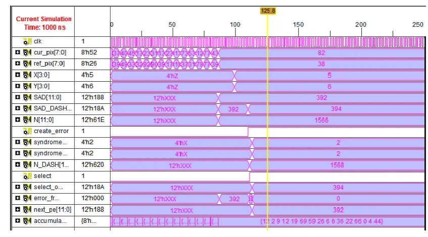
IV. RESULTS
The Fig 5 shows the BISDC_MECA top module. The 16 cur and 16 ref pixels, outputs of processing element SAD_CAL, N, create_error, SAD_DASH, output of coder X, Y, output of detector select, N_DASH,
[image:4.595.86.510.507.742.2]syndrome values, output of selector (error bit from syndrome decoder) select_out are given to the corrector. the corrector corrects the error bit and transfers to the next processing element as a error free bit.
International Journal of Emerging Technology and Advanced Engineering
Website: www.ijetae.com (ISSN 2250-2459,ISO 9001:2008 Certified Journal, Volume 3, Issue 7, July 2013)
164
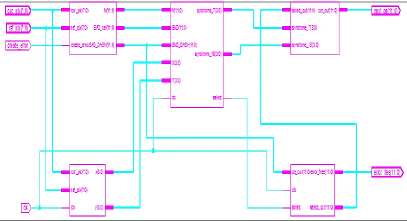
The synthesized block diagram of the design generated using verilog with Library has been shown in Figure 6. The synthesized block diagram is a top module of the Built-in-self Detection and Correction Architecture for Motion Estimation Computing Array i.e., meca_e_free.v consists of different sub modules which are interconnected to each other, these sub modules are
[image:5.595.94.501.228.449.2]processing_element.v, modulo.v, compressor3_2.v, full_adder.v, abs_diff.v, coder_A_n_B.v, detector.v, corrector.v, selector.v. The sub modules receive inputs from the top module and generate the outputs accordingly. In this report 1931-4 input LUTs are used out of 17344, 1116 Slices are used out of 8672,605 Slice Flip Flops are used out of 17344.
Fig. 6 synthesized output
V. CONCLUSION
This paper presents a built-in self-detection/correction (BIDC) architecture for motion estimation computing arrays (MECAs). Based on the error detection/correction concepts of biresidue codes, any single error in each processing element in an MECA can be effectively detected and corrected online using the proposed BISD and built-in self-correction circuits. The proposed architecture can reduce the processing cost, which increases the speedup as well as the throughput. The memory can keep the data path fully utilized in video processing function implementations which ensures high-speed operation and full utilization of the processing resources.
REFERENCES
[1] C. G. Peng, D. S. Yu, X. X. Cao, and S. M. Sheng, “Efficient VLSI design and implementation of integer motion estimation for H.264 SDTV encoder,” in Proc. IEEE Int. Conf. Solid-State Integr. Circuits, 2006, pp. 2019–2021.
[2] T. H. Wu, Y. L. Tsai, and S. J. Chang, “An efficient design-for-testability scheme for motion estimation in H.264/AVC,” in Proc. Int. Symp,VLSI Des. Autom. Test, Apr. 2007, pp. 25–27. [3] J. C. Tuan, T. S. Chang, and C. W. Jen, “On the data reuse and
memory bandwidth analysis for full-search block-matching VLSI architecture,” IEEE Trans. Circuits Syst. Video Technol., vol. 12, no. 1, pp. 61–72, Jan. 2002.
[4] R. J. Higgs and J. F. Humphreys, “Two-error-location for quadratic residue codes,” Proc. Inst. Electr. Eng. Commun., vol. 149, no. 3, pp.129–131, Jun. 2002.
[5] Z. L. He, C. Y. Tsui, K. K. Chan, and M. L. Liou, “Low-power VLSI design for motion estimation using adaptive pixel truncation,” IEEE Trans. Circuits Syst. Video Technol., vol. 10, no. 5, pp. 669–678, Aug.2000.
[6] P. Gallagher, V. Chickermane, S. Gregor, and T. S. Pierre, “A building block BIST methodology for SOC designs: A case study,” in Proc. Int. Test Conf., Oct. 2001, pp. 111–120. [7] X. Xiong, Y. L. Wu, and W. B. Jone, “Reliability analysis of