International Journal of Emerging Technology and Advanced Engineering
Website: www.ijetae.com (ISSN 2250-2459, Volume 2, Issue 10, October 2012)91
Performance Investigation of Active Power Line Conditioner
using Simulink
Ankita Singh
1, Sanjiv kumar
21
Research Scholar,
Department of Electrical Engineering, H.B.T.I. Kanpur, India.2
Asst. Professor
,
Department of Electrical Engineering, H.B.T.I. Kanpur, India.Abstract— Active power conditioners have been developed over the years to solve the problems to improve power quality. Among which shunt active power conditioners is used to eliminate load current harmonics and reactive power compensation. The controller ensures that the dc-side capacitor voltage is nearly constant with small ripple besides extracting fundamental reference currents. The PLL block assists the active filter to function even under distorted voltage or current conditions. The shunt APLC system is implemented with voltage source inverter and is connected at PCC for compensating the reactive power. The shunt APLC system is modeled and investigated under unbalanced non-linear load conditions using MATLAB simulation. The simulation results reveal that the active power filter line conditioner is effectively compensating the reactive power and improves power factor at point of common coupling.
Keywords—Active power line conditioners (APLC), PWM inverter, PLL, PI, PID, Fuzzy logic controller and Hysteresis current controller (HCC).
I. INTRODUCTION
To cancel the compensate the reactive power APLC is the suitable solution. The APLC concept is to use an inverter to inject currents or voltages harmonic components to cancel the load harmonic components. The more usual configuration is a shunt APLC to inject current harmonics into the point of common coupling (PCC). The APLC can be installed in a low voltage power system to compensate one or more loads; thus, it avoids the propagation of current harmonics in the system. The developments of different control strategies give APLC to a new location. As APLC compensate the reactive power and cancel the harmonics, it is also called as active power line conditioners (APLC). The concept of shunt APLC was first introduced by Gyugyi and strycula in 1976 .
II. BASIC COMPENSATION PRINCIPLE
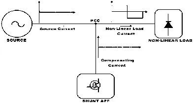
Figure 1 shows the basic compensation principle of a shunt active power filter.
[image:1.612.352.548.408.517.2]It is controlled a compensating current ic from the utility, so that it cancels current harmonics on the Ac side, and makes the source current in phase with the source voltage[7,8].
Figure 1 Basic Compensation Principle
The load current waveform, the desired mains current and compensating current injected by the active filter containing all the harmonics, to make mains current sinusoidal [6]. From Figure.1, the instantaneous currents can be written as
Is(t) = il(t) - ic(t) ( 1) Source voltage is given by
Vs (t) = Vm sin wt (2) If a non-linear load is applied, then the load current will have a fundamental component and harmonic components which can be represented as
International Journal of Emerging Technology and Advanced Engineering
Website: www.ijetae.com (ISSN 2250-2459, Volume 2, Issue 10, October 2012)92 Pl(t) = Vs(t) * Il(t) (4)
Pl(t) =VmI1 sin2wt *cosΦ1+VmI1 sinwt*coswt* sinΦ1+ Vm sinwt*∑In sin (nwt+Φn)
Pl(t) = P f (t) + Pr (t) + Ph (t) (5) P f (t) =Vm I1 sin2wt*cosΦ1 =Vs (t) * is (t) (6)
From equation (6), the source current supplied by the source, after compensation is
Is (t) =Pf (t)/Vs (t) = I1 cosΦ1 sinwt=Im sinwt (7) Where Ism =I1 cosΦ1
There are also some switching losses in the PWM converter, and hence the utility must supply a small overhead for the capacitor leakage and converter switching losses in addition to the real power of the load. The total peak current supplied by the source is therefore [12] Isp =Ism + Is1 (8)
If the active filter provides the total reactive and harmonic power, then is(t) will be in phase with the utility voltage and purely sinusoidal. At this time, the active filter must provide the following compensation current:
Ic(t)=Il(t)-Is(t) (9) Hence, for accurate and instantaneous compensation of reactive and harmonic power it is necessary to estimate, i.e. the fundamental component of the load current as the reference current [12,13].
[image:2.612.334.552.385.513.2]III. MODELING OF ACTIVE POWER LINE CONDITIONER The proposed shunt Active Power line conditioning diagram shown in figure-2.It has PWM voltage source inverter connected to a Dc capacitor reduction in current harmonics is achieved by injecting equal but opposite current harmonics at the PCC (point of common coupling).This process will cancel the original distortion and improving the power quality of the connected power system. The active filter is based on a PWM voltage source inverter is connected to the PCC through interface filter; the active filter is connected in parallel with the AC/DC converter. This inverter uses dc capacitor as supply and can switch at high frequency to generate the current that will cancel the harmonics from AC/DC converter. The current waveform for canceling harmonics is achieved by using VSI in the current controlled mode and the interface filter[12,13].
Figure 2. Simulink Model of Shunt APLC System with PWM VSI
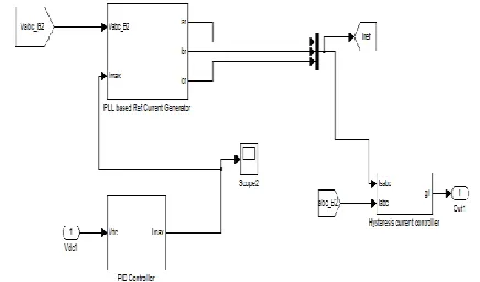
The model of APLC system contained three subsystems, PLL based reference current generator, PI or PID or Fuzzy logic controller and Hysteresis current controller as shown in Simulation model in fig 3.
Figure 3 Simulink model of Active power line conditioning block
International Journal of Emerging Technology and Advanced Engineering
Website: www.ijetae.com (ISSN 2250-2459, Volume 2, Issue 10, October 2012) [image:3.612.350.538.155.234.2]93 Figure 4 Simulink Model of PLL based Reference Current Generator
The PLL block tracks continuously the fundamental frequency of the system voltages (Vsc,Vsb,Vsa).The PLL based subsystem shown in Fig. 4 determines automatically the system frequency and the outputs of the PLL synchronizing block are Iar, Ibr and Icr the three phase currents.
B Modeling of PI, PID and Fuzzy Logic Controller
[image:3.612.90.247.324.494.2]This subsystem contained PI or PID or Fuzzy logic controller which on the difference of Vref and Vdc .The PI controller estimates the magnitude of peak reference current Imax and control the dc-side capacitor voltage of voltage source inverter.
Figure 1 Simulink Model of PID controller
Figure 2 Simulink Model of Fuzzy Logic controller
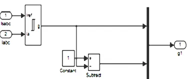
C Modeling of Hysteresis Current Controller
This subsystem Hysteresis Current Controller has been developed for switching of converters by comparing the actual current to the reference current. In the case of positive input current, if the error current e(t) between the desired reference current iref(t) and the actual source current iactual(t) exceeds the upper hysteresis band limit (+h), the upper switch of the inverter arm is become OFF and the lower switch is become ON as shown in the Fig.7. Here the hysteresis band limit h=0.5. The range of the error signal e(t) directly controls the amount of ripple voltage in the output current from the PWM-VSI.
Figure 3 Simulink Model of Hysteresis Current Controller
IV. RESULT ANALYSIS
A. Performance of Proportional Integral controller based APLC system
The simulation of APLC system is done with PI controller. The three phase unbalanced RL load is connected in parallel with diode rectifier load to the three phase ac mains and active power filter is connected in parallel at the PCC for suppressing the harmonics and reactive power.
The Source voltage, source current and load current under unbalanced RL with non linear load without compensation block are shown in Fig 8 (a), (b) and (c) respectively.
Figure 8 Simulation results before compensation under unbalanced RL with non linear load (a) Source voltage (b) source current and
(c) load current
[image:3.612.323.569.426.547.2]International Journal of Emerging Technology and Advanced Engineering
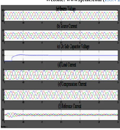
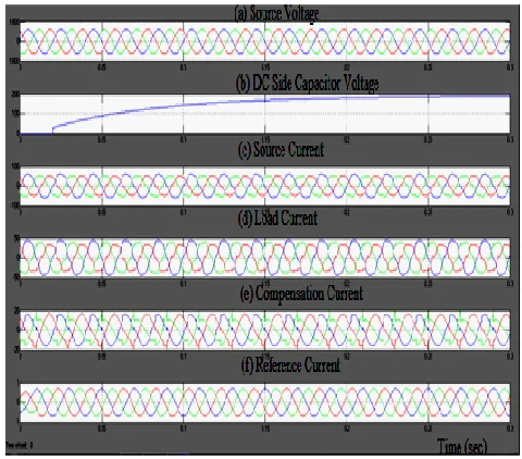
Website: www.ijetae.com (ISSN 2250-2459, Volume 2, Issue 10, October 2012) [image:4.612.52.283.150.399.2]94 Figure 9 Simulation results after compensation under unbalanced RL
with non linear load (a) Source voltage (b) Dc capacitor side output voltage (c) Source current and (d) load current (e) Compensation
current and (f) Reference current
The dc side capacitance voltage (Vdc) and its settling time are controlled by PI-controller; this controller reduces the ripple and makes settling time less; this is plotted in Fig 9 (b) for non-linear with unbalanced load (t=0.055s).
Figure.10 Power factor after compensation under unbalanced RL with non linear load using PI controller
The power factor is improve after compensation over nonlinear and unbalanced load and reach to unity (0.9998) when simulation of APLC System is done with PI controller.
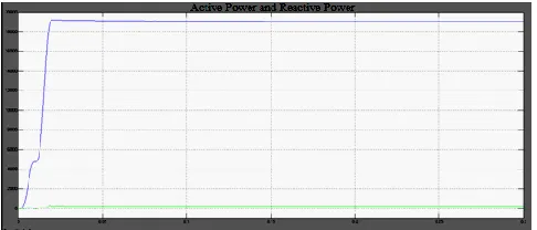
[image:4.612.325.566.200.364.2]The active power and reactive power are calculated by averaging the voltage-current product at the fundamental frequency 50 Hz, shown in Figure 11.
Figure.11 Active Power and Reactive Power without Active Power Line Conditioner
Figure .12 Active Power and Reactive Power with Active Power Line Conditioner
B. Performance of Proportional Integral derivative controller based APLC system
[image:4.612.324.569.393.567.2] [image:4.612.52.285.519.644.2]International Journal of Emerging Technology and Advanced Engineering
Website: www.ijetae.com (ISSN 2250-2459, Volume 2, Issue 10, October 2012)95 Figure .13 Simulation results after compensation under
unbalanced RL with non linear load” (a) Source voltage, (b) Source
current, (c) load current, (d) Dc capacitor side outputvoltage, (e)
Compensation current and (f) Reference current
[image:5.612.51.295.154.344.2]The dc side capacitance voltage (Vdc) and its settling time are controlled by PID-controller; this controller reduces the ripple and makes settling time less; this is plotted in Fig 13 (d) for non-linear with unbalanced load (t=0.053s)
Figure .14Power factor after compensation under unbalanced RL with non linear load
The power factor is improve after compensation over nonlinear and unbalanced load and reach to unity (0.9999) when simulation of APLC System is done with PI controller. The active power and reactive power of PID based APLC system are calculated by averaging the voltage-current product at the fundamental frequency 50 Hz, shown in Figure 15.
Figure. 15 Active Power and Reactive Power with Active Power Line Conditioner
C. Performance of Fuzzy Logic controller based APLC system
[image:5.612.323.563.382.593.2]The Simulation results for Fuzzy logic controller based APLC system under unbalanced RL with non linear load with compensation are shown in Fig 16.
Figure.16 Simulation results after compensation under unbalanced RL with non linear load” (a) Source voltage, (b) Dc capacitor side
output voltage, (c) Source current, (d) load current, (e) Compensation current and (f) Reference current
[image:5.612.53.286.455.560.2]International Journal of Emerging Technology and Advanced Engineering
Website: www.ijetae.com (ISSN 2250-2459, Volume 2, Issue 10, October 2012) [image:6.612.52.286.155.277.2]96 Figure. 17 Power factor after compensation under unbalanced RL
with non linear load
[image:6.612.48.291.324.428.2]The power factor is reach to unity when fuzzy logic controller is used in the place of PI and PID controller. This is the best power factor for APLC system.
Figure.18 Active Power and Reactive Power with Active Power Line Conditioner
The active power and reactive power of FLC based active power line Conditioning are calculated by averaging the voltage-current product at the fundamental frequency 50 Hz, shown in Figure 18.
D. Comparison of Performance of PI, PID And Fuzzy Logic Controllers
The settling time of the DC-side capacitor voltage of the inverter using PI, PID and fuzzy logic controller for non linear and unbalance load conditions; these are presented in Table 1.
Table 1 :Comparison of PI, PID and FLC for DC voltage settling time and power factor
Types of Controller
VDC settling time in seconds
Power Factor
PI 0.55 0.9998
PID 0.53 0.9999
FLC 0.50 1
The simulation is done for various non-linear unbalanced load conditions. PI, PID and fuzzy logic controller with PLL synchronizing control based compensator filter makes the source current balanced and sinusoidal after compensation. . The PI or PID or FLC ensures that the dc-side capacitor voltage is nearly constant with small ripple besides extracting fundamental reference currents. The performance of a PI, PID and fuzzy logic controlled APLC system is verified and compared under non-linear and unbalanced loads with various parameters that are presented graphically.
This simulation model of APLC system improves power factor on non-linear unbalanced load conditions.
Real power in watts (W) and reactive power in volt-amperes (VAR) are measured under non-linear with unbalanced load condition and are presented in table 2.
Table 2
Comparison of PI, PID and FLC for real Power and reactive Power
Compe nsation conditio
ns
Types of Controller
PI PID FLC
Without APLC P=14.68KW Q=0.85VAR P=14.68KW Q=0.85VAR P=14.68KW Q=0.85VAR With APLC
P = 34.50KW Q = 0.68VAR
P=34.80KW Q=0.45VAR
P= 19.1KW Q= 0.21VAR
The phase locked loop with Fuzzy logic controller based APLC system effectively compensates the reactive power and improves power factor.
V. CONCLUSIONS
International Journal of Emerging Technology and Advanced Engineering
Website: www.ijetae.com (ISSN 2250-2459, Volume 2, Issue 10, October 2012)97 APLC system is verified and compared under non-linear and unbalanced loads with various parameters that are presented graphically. This active power line conditioner system is tested and verified using MATLAB. The synchronous reference frame controller is used to extract the reference current from the distorted line current. This facilitates to improve the power quality parameters such as reactive power and power factor due to nonlinear load. The obtained results indicate that DC-capacitor voltage and the reactive power control can be adapted easily under non-linear load conditions.
REFERENCES
[1 ] Yacamini R., ―Power system harmonics. II. Measurements and calculations‖ IEEE Power Engineering Journal, vol. 9, (1995): pp. 51-56.
[2 ] Amoli M. E. and Florence T., ―Voltage, current harmonic content of a utility system-A summary of 1120 test measurements,‖ IEEE Trans. Power Delivery, vol. 5, (1990):pp. 1552–1557.
[3 ] Robert D H e n d e r s o n , P a t r i c k J . Rose ―Harmonics: The effect on power quality and transformer‖ IEEE Trans. Industry Applications, vol. 30, no.3, (1994):pp. 528-532.
[4 ] Singh B., Haddad K. A., and Chandra A.,‖A review of active power filter for power quality improvement‖, IEEE Trans. Industrial Electronics, vol.46. no.5, (1999):pp. 960-971.
[5 ] Peng F. Z., Akagi H., Nabae A., ―A new approach to harmonic compensation in power system- a combined system of shunt passive and series active filters ‖ IEEE Trans. Industry Applications, vol. 26, (1990):pp.983-990.
[6 ] Chen C. and Divan D.M., ―Simple topologies for single-phase AC line conditioning‖ IEEE Trans. Industry Applications, vol. 30, (1994):pp. 606–612.
[7 ] Nastran J., Cajhen R., Seliger M., and Jereb P., ―Active power filter for nonlinear AC loads,‖IEEE Trans. Power Electronic., vol. 9, (1994):pp. 92–96.
[8 ] Hafner J., Aredes M. and Heumann K., ―A shunt active power filter applied to high voltage distribution line‖ IEEE Trans. Power Delivery., vol. 12, (1997): pp. 266–272.
[9 ] Mendalek N., Al-Haddad K., Fnaiech F and Dessaint L.A., ―Nonlinear control technique to enhance dynamic performance of a shunt active power filter‖ IEEE Trans. Power application, vol. 150, (2003):pp. 373–379.
[10 ]Moran S., ―A line voltage regulator/conditioner for harmonic-sensitive load isolation,‖ in Conf. Rec. IEEE IAS Annu. Meeting, (1989):pp. 945–951.
[11 ]Akagi H., Kanazawa Y., and Nabae A., ―Instantaneous reactive power compensators comprising switching devices without energy storage components,‖ IEEE Trans. Ind. Applicat., vol. IA-20, (1984):pp. 625–630.
[12 ]Karuppanan P., Mahapatra K.K., ―PLL with fuzzy logic controller based shunt active power filter for harmonic and reactive power compensation‖ IEEE Conference, IICPT, Power Electronics, (2011):pp.1-6.