Systems Reference Library
File Number 1442-03 Form A24-3119-1
IBM 1442 Card Read-Punch Models 1 and 2
IBM 1442 Card Reader Models 3 and 4
This publication describes the functional and operational char-acteristics of the IBM 1442 Card Read-Punch Models 1 and 2 and the IBM 1442 Card Reader Models 3 and 4 with applicable data processing systems.
Special features available for the 1442 are described and, where appropriate, the program instructions are given for the feature.
This publication, Form A24-3119-1, is a major revision of Form A24-3119-0 and includes the information published in Techni-cal Newsletters N21-0011 and N21-001S.
Contents
IBM 1442 Models 1,2,3, and 4 ... 5
Modell Model 2 Model 3 Model 4 ... 5
5 5 5 Operating Features . ... 5
Keys, Lights, and Switches (Models 1, 2, and 4) . . . .. 6
Keys, Lights, and Switches (Model 3) . . . .. 8
Checking, IBM 1442 (Models 1, 2, and 4) . . . .. 8
Checking, IBM 1442 (Model 3) . . . .. 9
Special Features for IBM 1442, Models 1, 2, and 4. . ... 9
Card Image Feature ... 9
Read Card in Card Image ... 10
Punch and Stop in Card Image. . . . 10
Punch and Feed in Card Image. . . . 11
Card Read-Punch Adapter ... 11
Selective Stacker ... 11
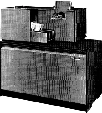
The IBM 1442 Card Read-Punch Models 1 and 2 pro-vide card input! output for data processing systems. Cards are read and punched serially.
The IBM 1442 Card Reader Models 3 and 4 are serial reader card units that provide input only to data processing systems. The basic difference between Models 3 and 4 is that they are designed to function with different processing systems.
Modell
The 1442 Modell (Figure 1) reads cards at a rate of 300 cards a minute and punches at a rate of from 50 cards a minute, when all 80 columns are punched, to 270 cards per minute when only one column is punched.
One radial stacker with a capacity of 1300 cards is standard equipment on the Model 1. An optional stacker is available, which provides separation of cards after they have been processed.
Model
2
The 1442 Model 2 reads cards at a rate of 400 cards a minute. Punching speed ranges from 91 cards a min-ute, when all 80 columns are punched, to 360 cards a minute when only one column is punched.
Two radial stackers, with a capacity of 1300 cards each, are standard equipment on the Model 2.
Model
3
The IBM 1442 Card Reader Model 3, which is used with the 1410 and 7010 data processing systems, han-dles punched-card input when the 1410 or 7010 is operating as a tape-oriented system. The Model 3 minimizes manual entry of information at the console.
It can be used to:
• Read calling cards that determine the sequence of loading from a master program tape.
• Load small utility programs. • Load sorting control cards.
• Enter constant factors into core storage. • Process miscellaneous or late transactions. • Process data correction cards.
The reading speed 6f Model 3 is 400 cards a minute. Cards are read serially at a single reading station, the same as with Models 1, 2, and 4.
IBM 1442 Card Read-Punch Models 1 and 2
IBM 1442 Card Reader Models 3 and 4
Cards must be punched in accordance with the BCD Standard Interchange Code, but the punching can be in any arrangement of digits, letters, special characters, or blanks. One character is read at a time, translated to BCD representation, and transferred immediately ( without buffering) to the processing unit. This trans-fer is serial by character and parallel by bit, and uti-lizes the channel approximately 120 milliseconds per card.
The 1442 Model 3 can be attached to a 1411 or 7114 process unit I/O channel via the input/output adapter. However, a 1442 Model 3 cannot use an I/O channel to which an IBM 1402 Card Read-Punch is attached. The 1442 read instructions, channel-status indicators, responses, and other controls are identical with the reading process of the IBM 1402. All other I/O equipment (tape, files, etc.) can be attached to the channel without restriction.
The read hopper holds 1200 cards. One stacker, with a capacity of 1300 cards, is standard on the Model 3.
Model
4
The IBM 1442 Card Reader Model 4 supplies input only at a reading rate of 400 cards a minute. Model 4 does not punch; but its read function is the same as that of the Model 2. A Model 4 can be attached to a system in combination with either a Modell or a Model 2. A maximum of two Model 4's can be attached to a system; the first requires a Card Read Punch Adapter feature.
Operating Features
The IBM 1442 Card Read-Puilctl provides a system with card input and output. The 1442 reads cards serially, column by column, beginning with column 1 and ending with column 80.
Card reading in the 1442 is accomplished through photo sensing; light energy is converted into electrical energy. Twelve photo sensors, one for each punch position of a card column, are exposed to light as holes in the card pass between the light source and the sensors (Figure 2). This reading principle provides high-speed serial reading.
The first card-feed cycle moves the card from the hopper to the read station where it is registered at column zero.
The read hopper holds 1200 cards. Two stackers, with a capacity of 1300 cards each, are standard on the Model 4.
A reading operation ( if called for) takes place during the second card-feed cycle. Each card column is read twice. During read-cycle 1, the punched hole is translated to BCD code and stored in the specified core-storage position. During read-cycle 2, the punched hole is again stranslated. The resultant BCD-coded character is compared against the character read into storage during the preceding cycle. The card is registered in column one at the punch station when the second card-feed cycle ends.
A punch operation (if called for) takes place during the third card-feed cycle. The character is read out of core storage, translated to the comparable punched-hole code, and punched in the card column positioned in the punch station. A second core-storage readout cycle occurs. At the same time, the punched-hole code just punched is translated back to BCD code and com-pared against the character read out of core storage during readout cycle 2.
When the card leaves the punch station, it is carried to the stacker by a continuously-moving mechanism.
If a second stacker is present, the card can be selected. Figure 3 illustrates the card path during reading or punching operations.
On Models 1 and 2 this processing sequence allows data to be read and punched into the same card.
After the IBM 1442 Models 1 and 2 punch the data into a card, the program can eject the card into the stacker and position the next card for punching. Pro-gram requirements can demand that the card not be ejected. In this case, the card remains in position, at the column following the last column punched, so that the 1442 can punch other calculated results into the card during subsequent punching operations.
Figure 2. Reading by Photo Sensors
6
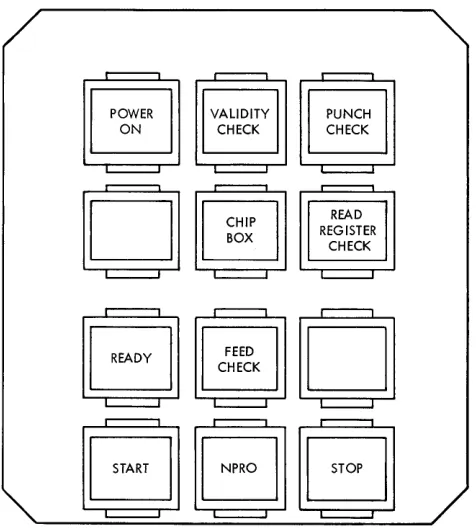
Keys, Lights, and Switches (Models 1, 2, and 4)
START KEY
Pressing this key causes one card to feed and the ready light to come on if the following conditions have been fulfilled:
• Power on • Card path empty • Cards in hopper
After a manual stop, pressing the start key (Figure 4) restores the IBM 1442 to ready status.
STOP KEY
Pressing the stop key removes the 1442 from ready status. The system is not affected unless the read punch is selected by the program; then the system stops in an interlocked condition.
POWER LIGHT
This light indicates that power is applied to the card read-punch control circuits.
VALIDITY-CHECK LIGHT
This light turns on when an invalid combination of punches is detected in the card column being read.
If the I/O check-stop switch is OFF, the light remains on until its program-tested. The program is flagged by the validity-check latch being set. No interruption of feeding or reading occurs.
If the I/O check-stop switch is ON, the card being read at the time of the error moves to the stacker before the machine stops. Pressing the NPRO key on the 1442 turns the validity-check light off.
C a r d - - -_ _ Cornering
Position
Stacker 1
Stacker capacity Stacker 2 1300 cards ( Optional
on Modell)
[image:6.612.305.535.493.695.2] [image:6.612.48.283.580.696.2]PUNCH-CHECK LIGHT
This light turns on when an error is detected in out-put punching. If the I/O check-stop switch is OFF, the light remains on until the check-stop latch is program-tested. No interruption in card feeding or punching occurs.
If the I/O check-stop switch is ON, card feeding is interrupted and the punch-check light remains on until the NPRO key on the 1442 is pressed.
READ-REGISTER-CHECK LIGHT
This light turns on (during punching and/or during feeding) when a card is off registration enough to pre-vent accurate data transfer. If the I/O check-stop switch is OFF, the light remains on until it is program tested, and card feeding is not interrupted.
If the I/O check-stop switch is ON, card processing continues until the end of the card cycle; then the machine stops. Pressing the NPRO key on the 1442 turns off the light.
CHIP BOX LIGHT
Models 1 and 2 are equipped with this light. The light indicates that the chip box is full or improperly posi-tioned. The 1442 is inoperative and in a not-ready condition when this light is on.
II :
'OoWN":II
VALIDITY CHECKPUNCH CHECK READ REGISTER CHECK
CJJm
s
~HE:~K
OJ
SSc;JJ
Figure 4. Keys and Lights for Models 1, 2, and 4
READY LIGHT
This light indicates that the card read-punch is ready to accept instructions from the processing unit. The following conditions are required:
• Power on
• Card registered at read station • Cards in hopper
• Stacker not full • No error condition
Note: After run-in, a card need not appear at the
punch station. If the first operation calls for punching, a read-and-eject cycle is automatically initiated before punching occurs.
FEED-CHECK LIGHT
The feed-check light indicates one of the following conditions:
• Card jam at punch station or at stacker.
• Card motion incorrect. (Detected by a card being in the wrong place at the end of the cycle.)
• Read lamp failure. (A machine circuit tests all read lamps during every read cycle. )
• Extra feed cycle. (Caused by failure of clutch to latch or to remain latched. )
• Failure of a card to feed from the hopper.
The card-motion check, card-feed failure, and feed-cycle check can be reset by emptying the hopper and clearing the transport. If a stacker or punch jam has occurred, a jam protection interlock prevents the NPRO key from clearing the feed. The operator must remove the jam manually. If a read lamp check occurs, an IBM Customer Engineer should be notified.
NON-PROCESS RUNOUT KEY (NPRO)
The NPRO key is used to clear the transport area of the last two cards. These cards are run into the stacker without being processed. The NPRO key is also used to reset the check circuits after a feed check, validity check, or a read register check. Successive feed cycles occur as long as the NPRO key is depressed.
LAST-CARD SEQUENCE (SYSTEM CONSOLE SENSE SWITCHA ON)
The 1442 stops when the last card moves into the read station. The start key can then be pressed to re-lease the interlock and allow the last card to be processed according to the stored program. During this feed cycle the last card indicator turns on and is interrogated if the last-card switch, on the system con-sole, is turned on (sense switch A on the 1447). The last-card indicator remains on until another feed cycle is initiated.
When the program is written, a Branch-If-Indicator-On instruction should be used. The d-modifier for "last
[image:7.612.70.308.435.701.2]card test" on the first 1442 attached to the system is the character "A"; for the second 1442 the d-modifier is the character "&."
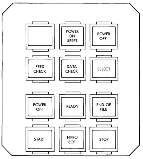
Keys, Lights, and Switches (Model 3)
POWER-ON KEY
This key turns power on for the motor, logic, and lights. Power can be turned off by the processing unit emergency-off switch or power-off switch (Figure 5).
POWER-OFF KEY
This key turns power off. Power is also turned off by the processing unit emergency-off switch on the 1410 or 7010.
START KEY
Pressing this key provides the final condition for mak-ing the machine ready, initiatmak-ing a feed cycle for load-ing the first card into the read station.
STOP KEY
Pressing this key places the 1442 Model S in a not-ready condition, causing the feed to stop at the end
Figure 5. Keys and Lights for Model 3
8
of the current feed cycle. When the start and stop keys are pressed simultaneously, a manual reset is gener-ated. No sequencing is required for pressing or releas-ing the keys.
STACKER SWITCH
This switch is operated by the cards when the stacker is full of cards and signals for operator attention.
HOPPER SWITCH
The hopper switch signals the presence or absence of cards in the hopper.
POWER-ON LIGHT
This light is ON when ac and dc power are ON.
READY LIGHT
This light is ON when the 1442 ModelS is mechanically ready to run by the processing unit.
FEED-CHECK LIGHT
This light is ON when a feed check has occurred.
DATA-CHECK LIGHT
This light is ON when a data check occurs.
SELECT LIGHT
This light is ON when the 1411 or 7114 selects the 1442 ModelS.
CUSTOMER ENGINEERING MODE SWITCH
The CE mode switch on the CE panel electronically dis-connects the 1442 Model S from the system, and per-mits a continuous-feed operation. This switch is for customer engineering use only.
Checking, IBM 1442 (Models 1, 2, and 4)
The four types of checking associated with the IBM
1442 Models 1, 2, and 4 are:
1. Validity Check. A validity check is performed 011
each character as it is read into core storage from the 1442. An invalid character can get into core storage, but validity-check circuits will detect it and cause a system stop (110 check-stop switch ON). The validity-check light on the 1442 also turns ON to indicate the check condition.
[image:8.613.43.285.435.703.2]ver-ify proper card registration and recognize an off-punch condition at the read station. Because the read station is singular and fixed in position, the relative position of the card in the feed and the punched-hole registration are checked as a combi-nation. The check is accomplished by reading out each specified card column twice. If a registration check occurs, the result of the first reading appears in the B-register; the result of the second reading appears in the A-register.
3. Read-Station Lamp Check. This check is: used to
verify correct photocell reading-mechanism opera-tion. The check is made between card-feed cycles by testing each photocell for output.
4. Punch Check. This check is a read back or echo
check between the actuated punch magnets and the
associated character in the punch field of core stor-age. This check is not used on the Model 4 which does no punching.
Each card column is checked before the next card column is punched. If a punch-check condi· tion occurs, the punch-check light turns ON and the 1442 punch operation stops (I/O check-stop switch on). The character sent to the punch station ap-pears in the B-register and the read-back character appears in the A-register. (This read-back character from the punch station is validity-checked before it is translated from card code to BCD code.)
If the I/O check-stop switch is off, the punch-check light remains on until the punch-check-stop indica-tor is program-tested. No interruption in card feed-ing or punchfeed-ing occurs.
Checking, IBM 1442 (Model 3)
Checking on the IBM 1442 Model 3 is divided into two general types: (1) Data Check, and (2) Feed Check.
DATA CHECK
A data check occurs when one of the following condi-tions is sensed:
• Illegal punch code-This check is made to determine if a character read is one of the 64 valid punch codes. • Cell-light check-This check is made to determine if all
12 photocells are functioning at the reading station after each card has been read.
• Skew Check-This check is made to insure that each character is free of excessive skew.
FEED CHECK
A feed check signals that something is wrong me-chanically in the 1442 Nlodel 3. This check causes the ready light on the 1442 Model 3 to go off. The feed
check comes on when one of the following conditions occurs:
• Jam Check-A switch in the feed indicates when more than one card is wholly or partially caught in the feed. • Card-Motion Check-A photoelectric cell near the read station checks for absence and presence of a card at specific timings.
• Extra-Cycle Check-This check signals for any mechani-cal-feed cycles taken without being impulsed.
Special Features for IBM 1442
Models 1, 2, and 4
Card-Image Feature
This feature is available for the IBM 1442 Card Read-Punch Models 1 and 2 and the IBM 1442 Card Reader. Model 4 with the IBM 1440 System only. The card-image feature provides the circuitry to convert binary-coded cards into BCD codes. The feature also provides
circuitry to convert BCD codes into binary-coded cards
for Models 1 and 2.
This feature also permits cards to be processed with multiple significant-digit punching in a single column.
12
11 A A
When reading in card-image mode, the validity check is suspended because all characters are con-sidered valid. Cards with interspersed, conventional punched codes and binary-coded data can be read.
Note: When this feature is installed on the first IBM
1442 attached to an IBM 1440 system, it also functions on the second 1442 installed on the system.
This feature permits reading punched data into the IBM 1441 unit without the normal translation from the standard punched card code to BCD code. In BCD mode, each card column of data is stored in two
adjacent positions of core storage. Similarly, the data in two adjacent core positions can be punched into one card column.
The readout time for reading a card in card-image mode is the same as for reading a card punched in standard card code.
Read Card in Card Image
Instruction Format.
Mnemonic Op code A-address B-address d-character
RCB
M
% Gn xxx RFunction. This instruction causes a read-card-image
operation to be performed by the presence of a 9 or 0 (zero) in the n position of the A-address. The 9 also selects the number-1 unit on the system; a 0 ( zero) in this position selects the number-2 unit when two units are on the same system.
The B-address is the address of the core storage where column-1 information is to be stored.
The instruction terminates when a group-mark with word-mark is sensed at location (B
+
LB ),where LB is the number of card columns to be read into the processing-unit core storage.
Word Marks. Special significance is assigned to a word
mark during the execution of a CARD IMAGE READ in-struction. The word mark is used to signal a change in the mode of operation. For example, in the card-image-read operation in the normal reading mode, each card column read is translated and stored in single core-storage locations until a work mark is detected in core storage. This signals the mode read-ing to change. Translation from the standard IBM
punched-card code is suspended. Suspension causes the card data beginning at the word mark to be stored in two adjacent core-storage positions for each column read. Detection of another word mark causes the reading to revert to the normal reading mode.
Timing.
Modell T=.Olll (LI
+
1)+
21+
1.3 (LB+
1) ms ModeI2T=.0111 (LI+
1)+
15+
1.0 (LB+
1) msAddress Registers After Operation.
I-AR A-AR B-AR
NSI BBB B
+
LB+
1Example. Transfer the data in card image form from
card read-punch 1 to the area in core storage la-beled RDBIN (0303), Figure 6.
If either character in a card column is read in
card-Label OPERANj
:~
40
Figure 6. Read Card in Card Image Mode
10
image mode, the complete card column must be read in the same mode. Therefore, the program must not have a word mark in any position that would cause a column to be divided into both the card-image mode and the standard IBM card code mode.
Punch and Stop in Card Image
Instruction Format.
Mnemonic Op code A-address B-address d-character
PCB
M
%Gn xxx PFunction. This instruction causes a punch-card-image
operation to be performed by the presence of a 9 or
o
(zero) in the n position of the A-address. The 9 also selects the number-1 unit on the system; a 0 (zero) in this position selects the number-2 unit when two units are on the same system.The B-address is the location of the data in stor-age to be punched. The data in core storstor-age is trans-ferred in ascending sequence to the card punch beginning at B-address until a group-mark with word-mark is sensed at (B
+
LB)' This information is punched in successive columns of the card at the punch station. A punching operation following another punch operation (no intervening card feed) causes the data at the B-address to be punched in the next successive card column. The program must be written so as not to exceed 80-columns of punch-ing per card. Should 80 columns be exceeded, data is lost.The operation is terminated by a group-mark with word-mark in the rightmost position of the field.
Word Marks. The word marks within the data being
punched are neither considered nor affected.
Timing.
Modell,
T=.Olll (LI
+
1)+
6.25+
12.5 (LB )+
210 msModel 2,
T=.Olll (LI
+
1)+
3.13+
6.25 (LB)+
160 msAddress Registers After Operation.
I-AR A .. AR B-AR
NSI BBB B
+
LB+
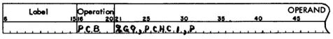
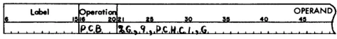
1Example. Punch the data in card image form on card
read-punch 1 beginning in the area labeled PCHCI
( 0303) and ending with a group-mark with word-mark (Figure 7).
Label
40
[image:10.612.302.540.673.701.2]Punch and Feed in Card Image
Instruction F onnat.
Mnemonic Op code A-address B-address d-character
PCB M % Gn xxx G
Function. This instruction is used to transfer data
from core storage into the card read-punch where it is punched into a card. When punching ends, the card is ejected from the punch station and selected into a stacker.
This instruction causes a punch-card-image opera-tion to be performed by the presence of a 9 or 0
(zero) in the n position of the A-address. The 9 also selects the number-1 unit on the system; a 0 (zero) in this position selects the number-2 unit when two units are on the same system.
Data in the core-storage position speci£ed by the B-address is transferred and punched into the ap-propriate card column. The rest of the data in ad-jacent core-storage positions is transferred, column by column, and punched in adjacent card columns until a group-mark-word-mark is sensed in core storage. The number of characters punched in the card depends upon the length of the B-£eld in core storage.
The B-£eld length can be from 1 to 160 core-storage positions, plus an additional position for the group-mark-with-word-mark. (Characters in excess of 160 will punch in column 81 and be lost.) When the punching operation ends, the card is ejected from the punch station and stacked.
Word Marks. Word marks are not affected. A
group-mark with word-group-mark is needed to end the opera-tion.
Timing.
Modell, T=.Olll (Lr
+
1)+
6.25+
12.5 (LB )+
210Model 2, T=.Olll (LI
+
1)+
3.13+
6.25 (LB)+
160 A period of 210 ms elapses before another card read-punch operation can he executed.Note: When a punch-and-feed operation follows
either a read-card or punch-and-feed operation, the card at the punch station is registered in column 1, and punching begins in column 1. When a punch-and-feed operation follows a punch-and-stop opera-tion, the card at the punch station is the card that was punched during the previous operation; punch-ing begins in the column adjacent to the last column punched.
Address Registers After Operation.
I-AR A-AR B-AR
NSI BBB B
+
LB+
1Example. Punch the data in card-image form on card
read-punch 1 beginning in the area labeled PCHCI
( 0303) and ending with a group-mark with word-mark, and then eject the card (Figure 8).
Card Read-Punch Adapter
This feature is required when the £rst IBM 1442 is at-tached to an IBM 1440 system. Adding a second 1442 to the same system does not require this feature. This feature provides the controlling circuitry necessary for the proper operation of the IBM 1442's.
Selective Stacker
This feature provides a second stacker for the IBM 1442 Modell so that cards can be selected under program control for special applications. The IBM 1442 Models 2 and 4 have two stackers each as standard equipment. Instruction Format. Mnemonic SS Op code K d-character 2
Function. This instruction causes the card at the punch
station to fall into stacker 2. Unless stacker 2 has been selected before the operation that ejects the card (READ or PUNCH FEED), the ejected card is di-rected to stacker 1.
Word Marks. Word marks are not affected.
Timing. T=.Olll (LI
+
1) msAddress Registers After Operation.
I-AR A-AR B-AR
NSI 2bb 2bb
Example. Enters selected card into pocket 2 (Figure
9).
Punch Column Skip
This special feature increases card output by allowing the punch portion of the attached card read-punch ( es) to space over a speci£ed number of card columns
Label
Figure 8. Punch-and-Feed in Card Image Mode
Label OPERAND~
Figure 9. Selective Stacker
[image:11.612.328.565.589.617.2]A24-3JJ9-J
without interlocking the system. The punch column skip operation is initiated by executing a PUNCH COL-UMN SKIP instruction.
Instruction Format.
Mnemonic Op code A-address B-address d-character
PSK M %Gn nnn C
Function. This instruction initiates the skip operation.
A-address of
%
Gn specifies one of the two card read-punches. The first 1442 attached to the system is designated by a 1 in the n position. The second 1442 attached to the system is designated by a 2 in the n position.The B-address is a 3-position number that speci-fies the number of card columns that will be spaced through the punch station. For example, if a punch column skip operation of 40 columns was specified, the 3-position B-address would be 040.
The Cd-character specifies a punch column skip operation.
Word Marks. Word marks are not affected.
12
TIrnlkTI
@International Business Machines Corporation Data Processing Division
112 East Post Road, White Plains, N.Y. 10601
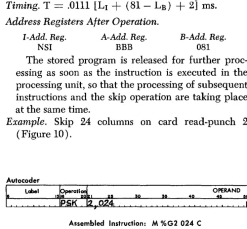
Timing. T
==
.0111 [LI+
(81-LB)+
2] ms.Address Registers After Operation.
I-Add. Reg. A-Add. Reg.
NSI BBB
B-Add. Reg.
081
The stored program is released for further proc-essing as soon as the instruction is executed in the processing unit, so that the processing of subsequent instructions and the skip operation are taking place at the same time.
[image:12.617.293.539.93.321.2]Example. Skip 24 columns on card read-punch 2
(Figure 10).
Autocoder
I"
Label rrati~ OPERAND7
Assembled Instruction: M %G2 024 C
G)
c:
::i
0)
c:
0
<
...
0
G)
~
READER'S SURVEY FORM
Manual Name: IBM 1442 Models 1,2, 3, and 4 SRL Form No. A24-3119-1
•
Is the material: res SatisfactoryEasy to read?
D
D
Well organized?
D
D
Fully covered?
D
D
Clearly explained?
0
0
Well illustrated?
0
0
• How did you use this publication? As an introduction to the subject For additional knowledge of the subject
'0
o
• Which of the following terms best describes your job?
•
Customer Personnel
~anager
0
Systems Analyst
0
Operator
0
Programmer
0
Trainee
0
Other ____________ _
IBM Personnel Customer Engineer
0
Instructor
0
Sales Representative
0
Systems Engineer0
Trainee
0
Other ____________ _
Check specific comment (if any) and explain in the space below:
(Give page number)
No
o
o
o
o
o
o
Suggested Change (Page0
Suggested Addition (Page )o
Error (Page0
Suggested Deletion (Page )Explanation:
Staple
A24-3119-1
Fold Fold
-.---*---BUSINESS REPLY MAIL
NO POSTAGE NECESSARY IF MAILED IN THE UNITED STATES
Attentionl Product Publication, Dept. 245
POSTAGE WILL BE PAID BY • . •
IBM Corporation
Systems Development Division Development Laboratory Rochester, Minnesota 55901
FIRST CLASS PERMIT NO. 387 ROCHESTER, MINN.
~---~-~---~---~--~---1
Fold Fold
I
llrnllir
<!>International Business Machines Corporation
Data Processing Division
112 East Post Road, White Plains, N.Y. 10601