Systems
GC27 -6999-2
File No. 5360/5370-30
Introduction
to.
Programming the
IBM 3270
-~-- ~
- - - -
-
---
-~---
~--- ---
-
-Ihi~g_Jditi~ (August 1977)
This edition replaces GC27-6999-1. Changes to this third edition viII
~e reported in subsequent revisions or technical newsletters.
Eefore using this publication in connection with the operaticn of IB! systems, refer to the latest IEII System/360 or System/370 SRL Hewsletter for the editions that are applicable and current.
Copies of this and other lBII publications can be obtained through your IEII branch office.
EEFORE YOU USE THIS BOOK
ihis book is for people who need to know what's involve~ in programming
the IBM 3270 Information Display System.
For those progra.aers who plan and code the messages seen on 3270 displays, this book may be the only book required.
For those programmers who also write the access method .acro
instructions or other I/C instructions, this book is to be used in conjunction with the appropriate access method or IBM Program Product :publications.
~~!_Ihis B~Q~_Is_Q!g~ni~§~
This book is divided into these sections:
1: SCREEN DESIGN
Introduces important 3270 ccncepts. Shows an exaaple of what a 3270
display message might look like, what coding elements are required to write this message in your program, and how teraiaal oFerator input might be handled.
2: SCREEI MAIAGEMEBT
Suggests macro definitions and programming routines that might be written to encode and decode messages to and from the display.
3: BTA" SUPPORT
Suggests including I/O operations (reading, writing, error recovery)
in a module separate from message formatting. Contains descriptions
and flowcharts to aid in writing error recovery routines for use
with BTA". Discusses sense/status analysis.
4: TeAM SUPPORT
Sugges~s bandling messages by means of two modules for the user's
application program. Eescribes the TCAM macro instructions that
affect the 3270. Suggests how to handle remote printers.
5: iTAM SUPPORT
Summarizes the VTAM information for the 3270. Describes using iTA"
with SIA and non-SIA 3270s. Suggests guidelines for making non-SIA
and SNA 3270s compatible in the same network.
~!h~~_~ook§_!Qy_~~_Beeg
As a general introducticn to the 3270:
io understand how the terminal operator sees the 3270:
I
j_§Yi9~!9~§i~g-!h§-I§§1-B~~y~!_Fe~tu~ ~~ IBM 3270~i§llay al§!~~§; GA27-2774
QR§!ato~~§~ui~_~Q£_th~_!]~-lll~ Inf~!i2D Displ~
As a reference on how the 3270 (including the printers) vorks:
111-~~70 Infor.ati9J-]is~~~e. CO.RoDeal p!SC~iEti2a, G127-2749
I
!~t!32Z2
!~~2!Jll..!ll0n Di~n,~l:_!I §I!~~':'Q!!~£!E~!2~' GA18-1017
--Suggested progra •• ing tools:
I green hooklet: llI-~119-lD!or.ation »!§Rl!~ Slst!!_Befer!9Ce
~Y!!~, GI20-1878
PaDel layout sheets: 111-111~-1D,or.atioA-DisplAI-~§~~Al2!l Sh,et, GI27-2951
If you are using BTl!:
1~J_2260 BTl! ~~1§~_§A!-!g_1I!~~1%11_~A!§~§igD-ili9!, GC27-697S
llJ_~~ste.LJ§~_Risk_2R~~ltiDg_~I§!~II~J!l!~9!!gniX!!i~J§ ACC!§! _J§!hod, GC30-5001
Ig~_R~oqra •• iDg SURR!§!§~1-iR~ ~h~270 IntorlJ!ign Di!RllI ~!!,
GC27-6977 (applicable to DOS Release 26 only)
Ig~_!§E!i~A-!_~TI!. GC27-6978
llJ_§I§!!!L~§O Operati!~~I§!~ __ §!sic T'lecg!I~D~catiR!§ 1~~1§§ lethod, GC30-2004
Ig~L!S BTAI, GC27-6989 gSL'§_BT1J, GC27-6980
If you are using TCI!:
Rl~~D!!S-!2!_TC1B vith_~l!J-1~10 19f9~.atioD ~isEla! ~§i~,
GC30-2021
g~_!~!8 PI2qrl •• er!s GUi~!!g-l§,er§n9' BADIA1, GC30-2024
g~_%~!8 U§!~!§-iYi!§, GC30-2025
g~L!§_~I_fI9~~.!t!§_§uig§, GC30-2034
If you are using 'TIB, or ICF/'!IB:
!ljJ_~oDceRts Ind Planni~, GC27-6998
!ljJ_Jacro~!l!.9.!WJLJ.§ll.!:§D~§, GC27-699S !lAJ_Jacro ~!DgJsg§ Guig§, GC27-6994
!lj.!_~l§1§Lpr2gn • .!!.I!§_.§.gig~ (DOS/'S, GC27-69S7; 05/'51, GC27-6996)
g~L!~~~!§LR.!og!!.!.Ii,!UI Li~~!n.l-InI, GC28-0688
J~!L!!!.! Concepts ASS llaDDin~, GC38-0282
J~!L!~18 ~I§te. ~~u!!ers i!lid! (refer to ~~BSU!§ !~ I];!!!liu for the appropriate fora Du.her).
J~1L!~18 BI~ro Langysg§_Bef~~§n£!, SC38-0261
A~!i!!!.! Bacro ~uaqe Guig§, SC38-0256
CHAPTER 1. SCREEN DESIGN. Field Concept •
How Fields Are Defined •
What Attributes May be Assigned to a Field • Example of Field Definition.
Panel Design
An Example of a Sequence of 3270 Panels.
Planning a Sequence of Panels. Defining the Purpose of Each Panel Using the Panel Layout Sheet
An Example of Laying Out a Panel •
Data Stream Coding. Orders •
Adding Orders to the Panel Layout Sheet. Coding the Panel
Repeat to Address Order.
Write Control Character (WCC). Analyzing Input Data.
The Operator's Response. Attention Identifier (AID) Input Data •
SBA Codes.
Program Attention Keys. Program Access {PAl Keys Program Function {PF)'Keys
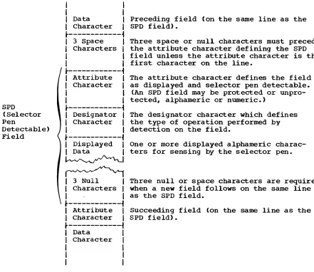
Selector Pen and Cursor Select Input and Output • Selector Field Format.
Designator Characters.
The Relationship of One Data Stream to Another. Modifying Existing Panels
Write Control Character (WCC). Erase Unprotected to Address Erase All Unprotected Command. Repetitive Output.
Program Tab.
CHAPTER 2. SCREEN MANAGEl-1ENT •
Decoding and Generating Data Streams.
Decoding Read Modified Input Data Stream.
Nonselector Pen or Non-Cursor Select Data Streams. Immediate Selector or Cursor Select Pen Data Stream Mixed Read Modified Input Data Streams
Building Output Data Streams. Static Data Streams.
Semi-Dynamic Output Streams. Dynamic Output Streams • Large Screen Size.
Copy Function for the 3271, 3272
3274 and 3276 Local Copy Function.
The Print Authorization Matrix for the 3274 and 3276.
The Matrix Structure. Defining the Matrix •
Local Copy Operation •
Host-Initiated Local Copy in Shared Mode for the 3274 and
3276.
Using Katakana Character Set Codes
CHAPTER 3. BTAM SUPPORT.
Telecommunications Management with BTAM • Techniques for Managing Devices •
The Advantages of a Terminal Control Program. The Advantages of a Master Terminal Program • Techniques for Keeping Track of Device Status Reliability and Error Recovery.
Remote Leased Line Event Completion Analysis Remote Dial Event Completion Analysis
Local Event Completion Analysis Sense/Status Analysis
CHAPTER 4. TCAM SUPPORT. Message Handling.
TCAM Macro Instructions •
TERMINAL Macro Instruction • INVLIST Macro Instruction. DCB Macro Instruction.
Defining the Local 3270 Cluster. INTRO Macro Instruction.
MSGFORf.1 Macro Instruction. SCREEN Macro Instruction • MSGLIMIT Macro Instruction • Handling Remote Printers.
Handling The AID Byte •
Handling Sense/Status Conditions.
ClmPTER 5. VTAM SUPPORT. VTAM with BTAM and TCAM •
Using VTAM with BSC and Locally Attached 3270s. Defining the Local 3270
Defining the BSC 3270
Logon Requests (BSC and Local Attachment) Logoff Requests •
Data Transfer Modes •
Data Transfer Using Record Mode • Using SEND/RECEIVE •
Input Considerations Output Considerations.
'.
Copy Considerations. .•
Network Solicitor Considerations Sense and Status Information • Data Transfer Using Basic Mode.
Input Considerations Output Considerations. Copy· Considerations.
Other Basic Mode Considerations. Sense and Status Information • Using VTAM with SNA 3270s
Defining the SNA 3270 Logon Requests.
Logoff Requests •
Guidelines for BSC and Locally Attached SNA Compatibility •
GLOSSARY.
INDEX •
ILLUSTRATIONS
Figure 1.
Figure 2.
Figure 3.
Figure 4. Figure 5. Figure 6.
Figure 7.
Figure 8.
Figure 9.
Figure 10.
Figure 11.
Figure 12.
Figure 13. Figure 14. Figure 15.
Figure 16.
Figure 17.
Figure 18.
Figure 19.
Figure 20.
Figure 21.
Figure 22.
Figure 23.
Figure 24.
Figure 25.
Figure 26.
Figure 27. Figure 28.
Figure 29.
Figure 30.
Figure 31.
Figure 32.
Figure 33.
Figure 34.
Figure 35.
Figure 36.
Figure 37.
Figure 38.
Figure 39.
Figure 40. Figure 41. Figure 42.
Figure 43.
Figure 44.
Figure 45.
Figure 46. Figure 47. Figure 48. Figure 49.
Figure 50.
Example of 4 Fields and Attribute Characters Results of Keyboard and Field Combinations
Example of Attribute Specification • • • • • • • • • • An Example of a Panel • • • • • • • • • • • •
Another Example of a Panel • • • • • • • Panel 1 of an Accounts Receivable Application • Panel 2, Showing the Results of a Search on a
Customer Name • • • • • • • • • • • • • • • • • • • Panel 3, Showing the Customer's Open Invoices. Panel 4, Showing Use of the Calculator • • • • • PanelS, Showing Selection of Invoices after Using the Calculator • • • • • • • • • • • • • • • • • Panel 6, Showing New Balance after Posting • • • Sign-on Panel Block Diagram • • • • • • • • • • Block Diagrams. • • • • • • • • • • • • • • • Sign-on Panel as written Out on Layout Sheet. • Panel Layout Including Attribute and Cursor Positions • • • • • • • • • • • •
Laying Out Field Attributes • • • • •
Text Items on Panel Layout Sheet. • • • • • • • • • Field Attributes; • • • • • • • • • • • •
Attribute Default Values • • • • • • • • • •
2
• 3
• 5 · 7
• 8 • 8
• 9 .10 • 11 .11 .12 .13 .13 .15 .15 .16 .17 .18 .18 .19
Completed Order and Attribute Information • Buffer Control Orders and Order Codes • • • • • Sign-on Procedure Panel Orders and Attributes • Attribute Character Combinations in Hexadecimal • Assembler Language Statements for Sign-on Panel Example of RA Order • • • • • • • • • •
• • .21
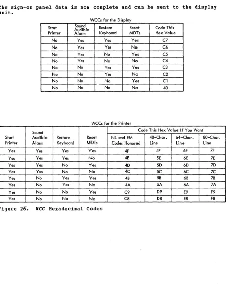
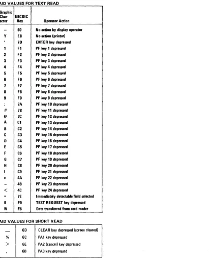
WCC Hexadecimal Codes • • • • • • • • • • • • • • • Sign-on Panel with Operator's Input • • • • • • • • Input Data Sequence • • • • • • • • • • • • • Attention Identifiers (AID) in Hexadecimal Codes • • Definition of Field for Selector Pen Operation. Sample Panel. for Selector Pen or Cursor Select Detection • • • • • • • • • • • • • • • • • • Modifying an Existing Panel--Basic Panel. • • Existing Panel with Error Message • • • • • • • Panel Layout Changes for Error Message (Keyed to
.22 .23 .24 .25 .26 .27 .27 .28 ~31 .32 .34 .34
Text) . . . • . . . . .35
Error Message Panel with Serial Number Field Erased .37
Example of EUA Use. • • • • • • • • • • • .38
Sign-on Panel with Three Erased Fields. • .38
Erasing Multiple Fields with EUA • • • • • • • • • • • • • 38
Example of Data Entry Panel. • • • • • • • .40
Data Entry Panel with Entered Data. • • • • .40
Employee Data Panel. • • • • • • • • • • • • .41 Panel Defined with Program Tab. • • • • • • • • 42
Relationship of Screen Management to Telecommunications Management and Application Programs. • • • • .43
Table of Requirements. • • • • • • • • • • • • .47 Example of Selector Pen Panel. • . • • • • • • • .49
Sample Mapping Table. • • • • • • • • • • • • • .50
Table of Control Unit and Terminal Information. • • .65
Example of a User-Built DECB Extension. • • • • .65
DOS, DOS/VS, BTAM Remote Nonswitched Line Read Completion Analysis. • • • • • • • • • • • • • • • • • • • • • • • .67
Figure 51.
Figure 52.
Figure 53. Figure 54. Figure 55.
Figure 56. Figure 57. Figure 58. Figure 59. Figure 60. Figure 61. Figure 62. Figure 63. Figure 64. Figure 65. Figure 66. Figure 67. Figure 68. Figure 69. Figure 70. Figure 71. Figure 72. Figure 73. Figure 74. Figure 75.
DOS, DOS/VS, BTAM Remote Nonswitched Line Write
Completion Analysis • • • • • • • • • • • • • • • • • • • 74 OS, OS/VS, BTAM Remote Nonswitched Line Write Completion Analysis. • • • • • • • • • • • • • • • • • • • • • • • .75 DOS, DOS/VS, BTAM Remote Dial Read Completion Analysis • • 80 OS, OS/VS, BTAM Remote Dial Read Completion Analysis • • • 81 DOS, DOS/VS, BTAM Remote Dial Write Completion
Analysis. • • • • • • • • • • • • • • • • • • • • • • • .86 OS, OS/VS, BTAM Remote Dial Write Completion Analysis • • 87 DOS, DOS/VS, BTAM Local Read Completion Analysis. • .92 OS, OS/VS, BTAM Local Read Completion Analysis. • .93 DOS, DOS/VS, BTAM Local Write Completion Analysis • .97 OS, OS/VS, BTAM Local Write Completion Analysis • • .98 Task Definition in Two Modules. • • • • • • • • • • 102 TERMINAL Macro for the 3270 • • • • • • • • • • • • 103 Invitation List for General Polling for Remote 3270 • • 104 Line Group DCB Macro for a Remote 3270. • • • • 104 Defining a Local 3270 • • • • • • • • • • • 105 MSGFORM Operation • • • • • • • • • • • 106 Syntax of the SCREEN Macro Instruction. • 206 SCREEN in an Outgroup Message Handler Program. • • 107
Handling the AID Byte (Example 1) 108
Handling the AID Byte (Example 2) • • • • 109 TCAM Sense/Status Problem • • • • • • • • • • • • • rO'9 Handling Sense/Status Messages. • • • • • 1"10 User Analysis of Sense/Status Messages • • • • • • • • • 111 Grouping Locally Attached 3270s into Logical Sets • • • 115 Processing a Terminal-Initiated Logon with the
Ihis eaition provides new progra •• ing infor.ation for the following
3210 co.ponents:
3274 Control Unit
3276 Control
Unit/Dis~laJStation
3278 Display station
3281 Printer
3289 Line Printer
Generally, these devices are co.patible with other 3270 ter.inals;
however, certain precautions are noted which .ust be observed in
integrating the. into your sJste.. This edition also corrects several
technical inaccuracies.
People dealing with infor.ation see it as a collection of individual elements. lor example, what we know about John Smith's emFloyment may be a collection of individual elements: his name, serial number, location, and date of hire. ~he size of the eleaent is the amount of data required to convey useful inforaation. You do not think of "J" and "0" and "B" and "B" as useful individually, but collectively, as the name JOBR. You do not think of JOHIS!ITB963981BOSTOI010262 as being useful collectively, but see the eleaents individually: name: JOBR S!ITB, serial number: 963981, location: BOSTON, date of hire: 01/02/62.
Each data eleaent has its own characteristics. In this examF1e, the serial number is 6 numeric digits and varies from employee to employee. The word "llBE" is 4 characters, is alphabetic, is all uppercase, and does not change. When people record these elements of data on paper they take on such additional characteristics as position (where on the sheet of paper the item is written), color (what ink or medium is used), size of t.he letters, and writing style.
In the past, when information was handled by a data processing device it was generally handled as an artificial entity called a record. The contents and characteristics of a record were priaarily determined by device requirements and little or no attention was given to the
individual information elements. Data processing users had to adjust their thought pattern to confora to the machine requirements.
The IB! 3270 Information Display System recognizes that people deal with individual units of information. The system has been designed to confora to human needs and requirements and it enables you to deal with data by individual elements or "fields," each with its own individual characteristics.
lou may describe data to the 3210 on a field basis and specify the characteristics or "attributes· of each individual field. The 3210 then provides program and data control based on your individual field definitions.
Each data field is established by writing a field attribute control code, or attribute character, as the first position of the field. A field is defined as the attribute character, plus all the data following it up to the next attribute character. The placement of attribute
characters defines the field lengths, and the content of the attribute characters defines the other field characteristics. In the following examples, the sy.bol [] designates an attribute character.
r---1
I
FIELD 1 FIELD 2 FIELD 3 FIElD 4I
I ----.-.
~ ~, ___
~I
I
r---,
r---,
r---,
r---,
r---1
I
t i l l NAME 12 IJOHN B DOE 13
I
SERIAL:I
4I
963981I
I ••• 1
I
L ___ J L ___ J L ___ J L ___ J L ___ JI
L ______________________________________________________________________ J
Figure 1. Example of 4 Fields and Attribute Characters
Field attributes can be modified or removed by a 3270 program. Removal of the attribute character ~ causes NAKE: JOBI DOE to be considered by the 3270 as a single field. Changing the content of the attribute
CD
alters the characteristics of SERIAL: even though SERIAL: itself has not been altered and it still ~e.ains associated with that attribute • .ill!! !!triR.!!!~§ 8ay be j§siq~g!2
~ FieldBesides length, which is controlled by the position of attributes, you may specify these additional characteristics with the attribute
character:
R!2!§~!ion: A field is either protected or unprotected. When it is protected, the operator cannot enter or modify data in any location within that field.
In an unprotected field, the operator can enter characters or can delete or modify characters that are already there. Beadings, labels, titles, and formats are commonly specified as protected. Any field in which the 3270 operator should enter or modify data must be specified as unprotected.
In Figure 1, NABE: would most likely be specified as protected. JOBI B DOE would be specified as protected if it was written by the computer and is to remain unchanged. If JOBI B DOE is to be entered or modified by the operator, the attribute ~ must specify unprotected.
Character Content: A field is either alpha.eric or numeric. An OFerator-can-enter alphameric, numeric, or special characters in an
alphameric field.
The numeric attribute is more complex; it depends upon whether the numeric Lock feature is present and which keyboard is attached to the display. Figure 2 shows what characters may be entered with various combinations of keyboards and field types.
!i§i&!lity ~~g Detec!abilit~: A field is either displayable or
ncndisplayable. When it is displayable and contains characters, those characters are displayed. When it is nondisplayable, any characters within that field will not be displayed. The nondisplayable attribute is-useful for entering classified or security information at a display unit that is in public view. londisplayable data is accepted by the 3270 but it is not visible on the screen.
If your 3270 system includes 3274's or 3276's you must take certain precautions since these control units, unlike the 3271, 3272, and
3275,-I
update screen images on a partial basis without removing previous imagesfrom the screen (there is no screen "blink"). To maintain security, make sure that prograas
• send a non-display attribute byte prior to sending the intended new non-displayable data to preclude its momentary appearance on the screen.
r---T---T---~---~---T---,
I I I I I I Resulting Characters I
I I Keyboard I Shift I I ~---T---~---~
I Keyboard I Numeric I Key I Field I I I Displayed I Read Into I I Type I Lock I Pressed I Type IProtectedlIn BufferlOn ScreenlStorage I
~---+---+---+---+---t---+---+---~
I Typewriter I No INo IAlpha INo I Lowercase I Uppercase I Lowercase I
I I I lor I I I I I
I I I I Numeric I I I I I
t---+---t---t---t---t---+---t---~
I Typewriter I No IYes I Alpha INO I Uppercase I Uppercase I Uppercase I
1
I
I lor I I I I I1-
I I I Numeric I I I I I~---t---t---+---+---t---+---t---~
I Typewriter I Yes INo IAlpha INO I Lowercase I Uppercase I Lowercase I
~---t---t---t---+---+---t---t---~
I Typewriter I Yes IYes I Alpha INo I uppercase I Uppercase I Uppercase I
~---+---t---+---t---+---~---~---~
I Typewriter I Yes INo I Numeric I No ICan only enter 0-9, period, I
I I I I I land minus sign~ any other I
I I I I I I characters lock keyboard. I
~---t---t---t---t---t---~
I Typewriter I Yes IYes INumericlNo ICan only press dup key; any I
I I I I I lother action locks keyboard. I
t---t---t---+---+---t---~
IData EntrYINo 1-- I Alpha INo IAlpha keys produce uppercase I
I I I I I I alpha characters. Numeric I
I I I I I Ishift key produces numeric I
I I I I I I characters. Alpha shift key I
1
1
I I I Ihas no effect. I~---+---+---+---+---+---~
IData EntrylNo 1-- I Numeric I No lNumeric shift key has no I
I I I I
1
I
effect. Alpha shift key II I I I I loverrides numeric specifica- I
I I I I I Ition and allows alpha I
I I I I I I character entry. I
"
~---+---+---+---+---t---~IData EntrylYes 1-- I Alpha INo IAlpha keys produce uppercase I
I I I I I lalpha characters. Numeric I
I I I I I Ishift allows numeric charact-I
I I I I I I er entry. Alpha shift key I
I I I I I lhas no effect. I
t---t---+---+---t---+---1
IData EntrylYes 1-- INumericlNo ICan only enter 0-9, period, I
I I I I I Idup, and minus sign. Any I
I I I I I I other characters lock all I
I I I I I Ikeys except for RESET key. I
I I I I I INumeric shift key allows I
I I I I I Inumeric character entry, I
I I I I I I alpha shift key allows alpha I
I I I I I Icharacter entry. I
L __________ ~ ________ ~ _______ ~ _______ ~ _________ ~ _____________________________ J
Figure 2. Results of Keyboard and Field Combinations
All characters within a displayable field can be displayed at regular brightness or at a high intensity so that they stand out among regular
display fields. High intensity may be used to call attention to error
conditions or to highlight protected or format fields. Normal intensity
may be used for all input fields, so the terminal operator can tell at
a glance which fields require operator action. You should net specify
unprotected fields as high intensity since such fields may become selector-pen-detectable (if this feature is installed) if the operator
enters a question mark or space as the first input character. Fields
are specified as either detectable or non detectable. When a field is
detectable, i t can be used for selector-pen or cursor-select operations. A nondetectable field location cannot be detected by the selector pen
[image:12.623.116.548.50.535.2]protected to prevent the operator's changing the content of the sensitive field.
1~g~2~!2§!~~: The most common operation of the 3270 (Read Modified) sends to the computer only those fields that have been entered, deleted,
or changed by the operator. The 3270 keeps track of such modifications
and uses that information to select data to send to the computer. If
you wish to pass a field into the computer regardless of modification,
I
you may assign the "modified" or "modified data tag (MDT) II attribute.However you should note that the operator can change the MDT attribute unless you also assign the protected attribute.
You can decide which combination of attributes you want within the
limitations specified in the 1~~ 1270 ~g~~D~D! ~escri~tion. Certain
attribute combinations produce additional characteristics. For example,
the numeric (limiting keyboard use) and protected (eliminating keyboard use) attributes seem contradictory but when specified together
automatically skip the cursor past the field.
You should also be aware that the computer is not limited by attributes. The computer can, for example, place alphabetic information in a field
defined as numeric, or protected, or both. The operator does not have
such liberty.
If you do not specify any combination of attributes, a field is assumed to have the following attributes:
• Alphameric
• Unprotected
• Displayable (at regular brightness)
• Nondetectable by the selector pen or cursor select
• lot modified
You will find that these attributes are the most commonly used.
The attribute character for each field uses a single nondisplayed and protected character position on the screen and serves as a visual separation between successive fields.
~~g~~!~
2!
Fielg De!!ni!!gnA typical sign-on procedure illustrates how you might define fields. Figure 3 illustrates a simple procedure in which the computer requests the operator to provide his name, location, and serial number.
"SIGN-ON PROCEDURE"
This field is a heading which the operator should not be able to alter. It is unnecessary for the words "SIGN-ON PROCEDURE" to be returned to
the computer when the ENTER key is pressed. This field should be
protected, alphameric, displayed at normal intensity, not detectable
by the selector pen or cursor select, and not modified. All default
0SIGN-ON PROCEDURE
0PLEASE ENTER YOUR SIGN-ON INFORMATION
mNAME:~_ 0LOCATION:0 ~ SERIAL NUMBER: {II ~
o WHEN ALL INFORMATION IS COMPLETE YOU MAY PRESS THE ENTER KEY
Figure 3. Example of Attribute Specification
!lj11l_~: "PLEASE ENTER ••• INFORMATION"
You should specify this field as protected. Remember that the
characteristics of a field are determined by the attribute character
at the beginning of the field. Field 1 and field 2 have identical
attributes and are adjacent to each other. You may choose to define
them separately and use two attribute characters or you may choose to
emit the attribute character at the beginning of field 2. In the latter
case the two headings combine to become a single field of greater length.
This field should be protected, alphameric, not modified, and not
detectable by the selector pen. The heading could be displayed at high
intensity. Specify the protected and high intensity attributes (the
two deviations from the default attributes).
!lj11l_!:
The area following "NAME:"The null area following NAME: is an input area for the operator and
must therefore be unprotected. The 3270 marks this field as modified
if anything is entered into i t , so you should not specify the modified
attribute. The default attributes (alphameric, unprotected, displayable
at normal intensity, not detectable by the selector pen or cursor
select, and not modified) apply. Use a default attribute at the
beginning of this field.
The maximum number of characters the operator can enter is determined
by the length of this field. The length is equivalent to the number
of nulls, or available positions on the screen, between the attribute character for field 4 and the attribute character for field 5.
!l£!bll_~: "LOCATION:"
The attribute character for this field is the same as that specified
for field 3; protected and high intensity should be specified. This
attribute prevents the operator from keying a name longer than the
maximum length desired. If the name is shorter than the maximum field
size, the operator presses the TAB key when the name is complete. The
TAB automatically skips the cursor past protected fields, such as this one, and stops at the first character position in which data can be
entered (the next unprotected field). In this example, the cursor
would be positioned for entry of location. If the operator attempts
to key too many characters (a name greater than 17 characters in the example) the cursor is positioned under this attribute for the 18th
character. The next keystroke attempts to destroy this attribute but
fails to do so because attribute characters are protected. The keyboard
is turned on. The operator's attention is assured since this condition requires pressing the RESET key to continue.
If the attribute character for this field vere omitted, the vord
"LOCATION:" would become part of field 4 and would be normal intensity and unprotected. This is undesirable since the operator could continue entering name information beyond the desired maxi.um length and could modify the heading information by entering data in the screen locations occupied by "LOCATION:."
!lj1~_§: The area following "LOCATIOI:"
This field is for operator input and therefore must be unprotected. The rest of the default attribute values apply and so a default
attribute may be used. You need specify only that a field is to begin following "LOCATION:." This field ends with the attribute character at the beginning of field 7, which determines the length of the field.
This field, like "NABE:" and "LOCATIOI:," should be specified as
~rotected and high intensity. This also limits the location field length to 5 characters. Note that if field 6, the input field for location, were defined as always being a five-character code, field 7, "SERIAL NUKBER:," could be defined as auto-skip to save the operator from having to press TAB after filling in the location code.
!1~11L!!: The area following "SERIAL NUBBER: II
The null area following "SERIAL BUBBER:" is an input area for the
c~erator and must be unprotected. It should also be specified as numeric so that if the o~erator tries to enter alphabetic data in the field (and the keyboard has the Numeric Lock feature), the keyboard inhibits entry of the incorrect character, the keyboard clicker shuts off, and the "input inhibited" indicator appears to notify the operator of the error. The improper character does not appear on the screen, and the correct digit may be entered after the operator presses the RESET key.
The serial number in the exam~le always contains a fixed number of digits and is the last field entered. The maxiaum length of the field is determined by the location of the attribute for the next field. But the next field in the example is too far away (IIHHEI ALL ••• KEY").
Ey placing an additional attribute character following input field 8,
the operator cannot enter a serial number that is too long. If the Fositions allocated to the serial number are filled, the next keystroke locks the keyboard, as in the name and location fields.
This additional length check is used here because this is the last
field to be entered. If you had another field to enter after SERIAL NUMBER, it might be more advantageous to oait this length check, as explained in field 9.
FIELD 9: The area between the additional attribute described in Field a-and-HWHEN ALL ••• KEY"
field, which is the next place you want to key data. This technique saves keystrokes for the operator. When the operator keys the last character of the preceding fixed-length field, the cursor normally enters the next field, which may be protected. But since the next field is auto-skip, the cursor skips this intervening protected field and automatically positions itself for entry of the next field, without an extra keystroke.
11jl~_lQ: "WHEN ALL ••• KEY"
ihis field is a heading which the operator should not be allowed to change. It need not be high intensity and thus it may be defined as Frotected only. Field 10 does not automatically terminate when the last screen position is reached. The field definition continues from the bottom right screen Fosition to the upper left screen position until the next attribute character is reached. This is called
"wraparound." Keep this in mind, particularly if you define the last field on a screen as unprotected!
Since fields 9, 10, and 1 are adjacent to each other (by wraparound) and all have the same attributes, they may be combined into a single field by the omission of attributes before "WHEN" and "SIGN-ON." The result is a single protected field beginning after the input area for serial number, wrapping around the screen, and terminating either at "PLEASE" or. at "NAME" if fields 1 and 2 have been previously combined.
Combining fields in the above manner may be convenient but may cause confusion and error if you change the screen layout later. It is a better practice to specify seFarate fields in all cases.
the panel is completely formatted when the fields are positioned, the attribute characters are all defined, and the cursor is placed. Yo'u must now begin the transition from the visual image, or human-oriented panel, to the detailed data necessary for the 3270 to implement your Fanel design.
You can think of a panel as a single 3270 display screen image created by your program. (The term "screen" or "screen image" or "display image" could also have been used.)
If the terminal operator filled in the information requested in the Fanel in Figure 4, he might receive another panel such as the one shown in Figure 5.
SIGN-ON PROCEDURE
PLEASE ENTER YOUR SIGN-ON I NFORMA TION
NAME: LOCATION:
SERIAL NUMBER:
WHEN ALL INFORMATION IS COMPLETE YOU MAY PRESS THE ENTER KEY
YOUR SIGN-ON HAS BEEN ACCEPTED. PLEASE CHOOSE ANY OF THESE PROCEDURES
ACCOUNTS RECEIVABLE PFl
PAYROLL PF2
PERSONNEL PF3
PLEASE PRESS THE DESIRED PF KEY
Figure 5. Another Example of a Panel
Assume you are given the assignment of designing the panels for an accounts receivable applicaticn. You are to create the panels that will allow a terminal operator to post a customer payment against his unpaid invoices. The terminal operator will be sitting at a 3210 work station, removing checks and invoice copies from envelopes. If the invoice copies are returned with the check, the terminal operator will for each invoice enter the customer number, payment, and invoice number. If the invoice copies are not returned, the terminal operator will have to find the customer number based on the customer name and then decide which open invoices to apply the payment against. It will be helpful if the operator has some way to add various open invoices to find a combination that totals the pay.ent.
The 1920-character panels that follow show one possible solution.
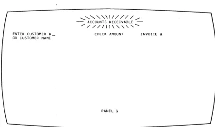
The first panel in the application is shown in figure 6. If the invoice copies come with the check, the terminal operator can enter the customer number, amount, and invoice number, and press the EITER key •
[image:17.615.50.493.428.690.2]ENTER CUSTOMER # OR CUSTOMER NAME
... " ' \ 1 / / / / / /
- ACCOUNTS RECEIVABLE -,/ / / / / 1 1 \ " " ...
CHECK AMOUNT INVOICE #
PANEL 1
!his posts the pay.ent against the specified invoice. The terminal operator can then post the next payment and so forth; so long as the customer nuaber and invoice number are known, only panel 1 is displayed.
If~ however, no invoice is returned and the customer number is not known, the custo.er na.e can be entered. The name need not be the complete naae of the company; it can be the first na.e of the company. In our example, the check says only "CAPITOLft so that is what the
oFerator enters. When the name has been entered, the terminal operator presses the EITER key. The custoaer number is missing, so Panel 2 is displayed.
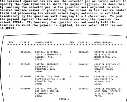
Panel 2, shown in Figure 7, shows all customers and customer numbers phonetically si.ilar to the name entered in response to Panel 1. Item nu.bers in Panel 2 allow the ter.inal operator to select one by using a corresponding Prograa Function (PP) key (see "Program Attention Keys" in this section).
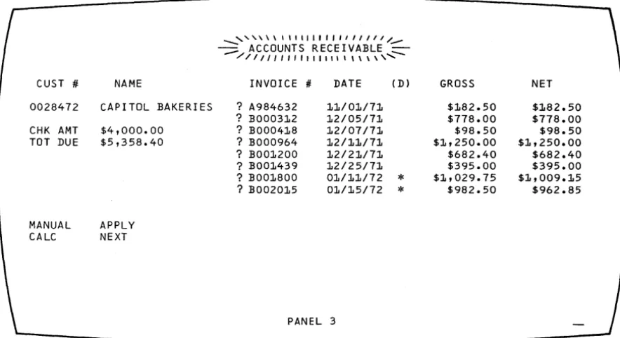
Is a result of terminal operator response to Panel 2, Panel 3 (shown in Pigure 8) displays all open invoices for the identified customer. ihe ter.inal operator can now use the selector pen or cursor select to specify the open invoices to which the payment applies. Be does this by touching the selector pen to the question mark adjacent to each desired invoice number or positioning the cursor in the invoice number field and processing the cursor select keys; selection is verified i •• ediately by the question mark changing to a
>
character. To post the pay.ent against the selected invoice numbers, the operator can select APPLY. If, however, the operator can not easily tell the invoices to which the payment is applied, he can select CALC instead of IPPLY.ITEM CUST # NAME/ADDRESS ITEM CUST # NAME/ADDRESS
* * * * * * * * * * * *
* *
* *
* *
*
* *
*
* *
* *
* *
*
* * * * * *
*
* *
*
*
1. 001.0341. CAPITAL AVIATION 5 0052693 CAPITOL ELECTRIC 71.1 HILLSBOROUGH ST. 56 STATE ST.
RALEIGH, N.C. MONTPELI ER, VT.
2761.1 05602
2 0028472 CAPITOL BAKERIES 6 0084362 CAPITOL FEATHER CO.
1.800 MAIN ST. 899 LOGAN ST.
COLUMBIA, S.C. DENVER, COLO.
29201. 8021.7
3 0034020 CAPITOL COLA CORP 7 0048729 CAPITAL GLASS CO. 1.439 PEACHTREE ST. NE 121. STATE ST.
ATLANTA, GA. ALBANY, N.Y.
30309 12201
4 0041.938 CAPITAL DRUG CO. 8 0038492 CAPITOL HOLDING CO. 201 NORTH 9TH ST. 1609 SHOAL CREEK B
RICHMOND, VA. AUSTIN, TEXAS
232:1.9 78701
PANEL 2
[image:18.620.120.561.258.612.2]__ ... , , , \ \ \ \ \ 1 I I I I J , , I I I 1 1 1 / _
~ ACCOUNTS RECEIVABLE ~
/ / 1 1 1 " " , 1 1 1 1 1 1 1 \ \ \ \ , ...
CUST #. NAME INVOICE #. DATE CD) GROSS NET
0028472 CAPITOL BAKERIES ? A984632 11/01/71 $182.50 $182.50
? BOO0312 12/05/71 $778.00 $778.00
CHK AMT $4,000.00 ? BOO0418 12/07/71 $98.50 $98.50
TOT DUE $5,358.40 ? BOO0964 12/11/71 $1,250.00 $1,250.00
? BOO1200 12/21/71 $682.40 $682.40
? BOO1439 12/25/71 $395.00 $395.00
? BOO1800 01/11/72
*
$1,029.75 $1,009.15? B002015 01/15/72
*
$982.50 $962.85MANUAL APPLY
CALC NEXT
PANEL 3
Figure 8. Panel 3, Showing the Customer's Open Invoices
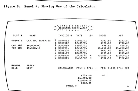
Selecting CALC displays Fanel 4 (Figure 9); this is the same as Panel 3 exce~t that ACCOUNTS RECEIVAELE which was high intensity in Panel 3
is now normal intensity in Panel 4. A new line with CALCULATOR in high
intensity indicates the screen mode and explains the PF keys' ,functions. The terminal operator can nov use the lower right hand quadrant of the screen as a "scratch pad" to figure out a combination of open invoices
that will total the payment check. This use of one part of the screen
for a separate function is sometimes called a "split-screen capability."
ihe calculator could be programmed a number of different ways. It
could, as our example illustrates, show all invoice numbers selected
(shown with
>
in Figure 9) prior to selecting CALC in one column inthe CALCULATOR quadrant and in another column show any balance remaining from the check amount after subtracting the selected invoice numbers. In Figure 9, Panel 4 is shown as i t would appear if the terminal operator had first selected four invoice numbers and then selected
CALC. In this example, the selected invoices equal the check amount
so .00 is shown as the balance after subtracting the selected invoices.
-Panel 4 shows that the CALCULATOR could also allow the operator to key in amounts and add or subtract them from the check amount (pressing PFl in our example adds keyed-in amounts; PF2 subtracts one keyed-in
amount from another). To start over at any point, the operator can
~ress PF3 to clear the calculator quadrant. In our example, the selected invoices equal the check amount, so they can now be posted.
But first the terminal o~erator must leave the CALCULATOR routine by
~ressing PF4 (RETURN). This displays Panel 5, shown in Figure 10.
Panel 5 is the same as Panel 4 except that, with the operator having
signaled completion of the CALCULATOR, that word now appears in normal
intensity and ACCOUNTS RECEIVAELEonce again appears in high intensity.
I
[image:19.620.51.493.60.301.2]CUST #I
0028472
CHK AMT TOT DUE
MANUAL CALC
NAME
CAPITOL BAKERIES
$4,000.00 $5,358.40
APPLY NEXT
ACCOUNTS RECEIVABLE
INVOICE #I DATE (D) GROSS NET
? A984632 1010/010/710 $1082.50 $1082.50 > BOO03102 102/05/710 $778.00 $778.00
? BOO04108 102/07/710 $98.50 $98.50
> BOO0964 102/1010/710 $10,250.00 $10,250.00
? BOO1200 12/210/71 $682.40 $682.40
? BOO1439 102/25/71 $395.00 $395.00
> 130010800 010/110/72
*
$10,029.75 $1,009.15> 130020105 01/15/72
*
$982.50 $962.85... " , \ \ \ \ , I I I I I I I I I I I 1 1 I I I r r I I I / I / /
~ CALCULATOR PF1o= + PF2= - PF3= CLEAR PF4= RET ~
/ / / I I 1 I 1 1 1 I I 1 I I 1 I I I I I 1 I I 1 1 I , , \ \ \ \ \,,,,,
PANEL 4
$778.00 .00 $1,250.00
$1,009.105 $962.85
Figure 9. Panel 4, Shoving Use of the Calculator
CUST #I
0028472
CHK AMT TOT DUE
MANUAL CALC
NAME
CAPITOL BAKERIES
$4,000.00 $5,358.40
APPLY NEXT
_ , \ \ \ \ 1 1 1 1 1 1 1 1 1 1 / / / . /
~ ACCOUNTS RECEIVABLE
---
/11111111111\\\\,"""-INVOICE #I DATE (D) GROSS NET
? A984632 101/01/710 $182.50 $182.50
> BOO03102 102/05/71 $778.00 $778.00
? BOO04108 102/07/71 $98.50 $98.50
> 13000964 102/110/71 $10,250.00 $1,250.00
? BOO1200 102/210/71 $682.40 $682.40
? BOO1439 102/25/71 $395.00 $395.00
> BOO1800 01/110/72
*
$1,029.75 $1,009.15> 130020105 010/15/72
*
$982.50 $962.85CALCULATOR PF1= + PF2= - PF3= CLEAR PF4= RET
$778.00 .00
PANEL 5
$1,250.00 $1,009.15 .
$062.85
figure 10. Panel 5, Showing Selection of Invoices after using the Calculator
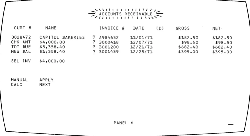
[image:20.613.126.567.55.314.2] [image:20.613.113.570.291.594.2]CUST #
0028472 CHK AMT TOT DUE NEW BAL
SEL INV
MANUAL CALC
NAME
CAPITOL BAKERIES $4,000.00
$5,358.40 $1,358.40
$4,000.00
APPLY NEXT
_ " \ \ ' 1 1 I 1 1 1 1 1 1 1 1 / -:::::; ACCOUNTS RECEIVABLE :::
/ I I , , I I , I I 1 \ \ \ \ " INVOICE # DATE (Dl
? A984632 11/01/71
? BOO0418 12/07/71
? BOO1200 12/21/71
? BOO1439 12/25/71
PANEL 6
GROSS
$182.50 $98.50 $682.40 $395.00
Figure 11. Panel 6, Showing New Balance after posting
NET
$182.50 $98.50 $682.40 $395.00
I
Not all of the 3270's possibilities are shown in these six panels andnot all users will have the selector pen or cursor select; this example was designed only to show what panels are and how the 3270 can be used.
Note that, in the above example, the terminal operator does not see as many panels as the programmer must create; not all panels necessarily
appear to the operator in any given application. What the programmer
regards as separate panels may appear to the terminal operator as one changing panel.
In the above example, a number of additional panels or variations to
the panels shown would be required. For example, if the terminal
operator presses an invalid PF key, a variation of the panel would be reguired to send a message to the operator over the panel presently at
his display. In programming panels that are variations of one main
panel, it may be useful to assign panel designations (for example,
Panel 4A, 4B, and so forth) for variations of Panel 4.
After an application program has been defined, the informaticn that will be passed between the program and the terminal operator must be
defined. This information can be thought of as output panels and input
response to panels. Usually, you will be able to approximate the
seguence of panels. The exact sequence of output panels often depends
on the input response to panels. The following discussion shows one
way to define a sequence of panels.
~~!i~iDg 1~~ E~££~
Q!
£g£~ ig~!Assuming you have a good understanding of the type of application program (such as data entry, order entry, or inquiry) and the kind of information that must be exchanged and processed (such as custcmer name, invoices, and check amounts), you can consider which panels come
first. Suppose the first panel required is a sign-on panel, as shown
[image:21.613.55.494.60.299.2]Panel 1 Sign-on panel
Figure 12. Sign-on Panel Block Diagram
Panel 1 Sign-on panel
Choose Pane I 2 Prog ram panel
No
Figure 13. Block Diagrams
Request Sign-on Again panel
PanellA
After sign-on, the next panel might allow the terminal operator to choose one of several different applications or procedures that he would use. But what if the name or word entered was not an authorized sign-on? Another panel might tell the terminal operator about this and ask him to re-enter a sign-on name. Figure 13 illustrates a
technique, sometimes called "block diagramming," that may help in laying out a sequence of panels.
~§i~g !he R~el LaYQut Eh~~!
After block diagraaming the panels in the application or procedure, you are ready to decide cn the exact contents of each panel: the fields that will be in the panel, what attributes each field will have, and what words will be displayed in the panel. This can be done on graph Faper. The I~~ 3270 !~!Q~g!ig~ ~!~ ~2!g! 19~Qut Sh~!, GX27-2951 is useful for layout.
One of these sheets can be used for each panel. After laying out a sequence of panels, you have a collection of panel layout sheets. Using the information on these sheets and the block diagram showing the
relationship between panels, the program can be written to send the panels to a terminal and handle an operator's response to them.
Now that you have written out what you want the terminal operator to see, you can define as fields the separate items of displayed text and spaces you are allowing for operator input. Remember that a field is always preceded by an attribute character. The attribute character cccupies a space on the panel even though it appears as a blank space to the operator. Before deciding the attributes of a field, insert SODe character such as A on the layout sheet to Indicate the space for the attribute character. As you get used to creating panels, you may want to enter the A at the same time you are laying out the text. You should also show the cursor location on the panel layout sheet to indicate to the operator where to start his response. The cursor position can be indicated by an underscore (_) under the space where you want it to appear, or you might enclose the space or characters in a rectangle. After adding the indications for attribute characters and the cursor position, the sign-on panel appears as shown in Figure
15.
You could have designed the panel as one long field (or even no field at all), but if you did, you would not be taking advantage of the 3270's
caFa~ilities. If you designate various items on the panel as fields, each field can have different attributes, as discussed in "What
lttri~utes May be Assigned to a Field."
For example, you might want the fields NAME:, LOCATION:, and SERIAL NUEBER: to have high intensity attribute to focus the operator's attention on them, because these fields indicate where the operator enters information. You might want to protect the fields other than the operator input fields so the operator could not erase them; the cperator input fields following BABE:, LOCATIOB:, and SERIAL NUMBER: should be unprotected so the operator can type in information. The operator input field following SERIAL BUMBER: can ~e numeric to allow some work station editing; the operator would not be allowed to
accidentally enter an alphabetic character. Field length can be defined by beginning a new field where you want the previous field to end (in SODe cases, this new field serves only to give a length attribute to a Frevious field).
Baving decided on these attributes, you can use the columns on the right side of the layout sheet to record the locations and attributes of the fields you have created. Your recording in these columns might alpear as in Figure 16.
The use of these columns depends on whether the panel designer also codes the panels or only designs thea. The information now on the layout sheet can be used to write a line of code that, when sent to the display, displays your panel with its specified field
01 02
03
04
05 06 07 08 09 10 11
12
13
Figure 14. Sign-on Panel as Written Out on Layout Sheet
COLUMN
09 10 11
12
13
ATTRIBUTE DISPLAY BUFFER
OR- HI
I
SEl NON MDT ITEM PRINTER ADDRESS PROT NO. DISPROW COL DEC HEX DERS INT DET PRT ON
\ ~ 1\
V'
d
t4-
d.
V
..
~!a
,
V
V+
ltJ
1
5"
lD
:JS
V V~
f.D
3~1
1
I
v'
v
'3
1
liD
v
q
1
~~v:-1O 10 ,f-
."
Figure 16. Laying Out Field Attributes
You must communicate certain information to a 3270 device or its control unit so that i t can use the panels you have designed. This information includes commands, control characters, orders, and data.
Commands control such things as whether you write to or read from a display and whether the screen is erased before new data is written. For the examples given below, assume that you begin with a clear screen: all writes to the 3210 are Erase/Write or Erase/Write Alternate (for 960, 2560, 3440, or, optionally, 1920 character displays) commands and all positions are set to nulls. (Commands are discussed in more detail in this chapter under "The Relationship of One Data Stream to Another." Refer to the ]ll~ ~Q!E2~~~! D~§£~i£tiQn for the command codes. Note that the only comm.and codes used for a 3270 with VTAf! support are those listed under "Remote" in the command code table in the 3270 ~Q.!!.E2nent !~§£!iEtio~.) Control characters are used with certain commands to
Ierform such functions as sounding the audible alarm, formatting the printer, and restoring or enabling the keyboard. (Control characters are discussed later in this section.) Orders are instructions written to the 3270 to tell the display unit how to format your panel. They centrol the creation and placement of fields and data. You may reduce the size of your data streams by careful order selection. (Orders are discussed below.)
Orders (1) position, define, and format data being written to the device; (2) erase selected unprotected data stored in the device; and
(3) reposition the cursor.
Three orders provide enough instruction to format every panel:
• Start Field (SF) order: Specifies that the next character is an attribute character.
• Set Buffer Address (SEA) order: Specifies an address for data and successive orders.
• Insert Cursor (IC) order: Moves the cursor to the current buffer address.
or inquiry responses, and the data that the operator has that must be provided to the computer, such as serial number, part number, or
quantity desir€d. The orders and text are sent to the display unit
and are interpreted by a control unit to which the display unit is
attached. The control unit formats the panel text before i t is actually
displayed at the display station.
I
The back of the panel layout sheet is used for writing the panel orders. ihe h~adings at the top of the columns indicate what the columns should contal.n.
ihe first six columns as shown in Figure 11 identify items in the text,
their addresses, and the orders required to format them. The column
headings are explained below:
• ITEM: Refers to any part of the panel that requires one or more
orders to the control unit to format i t . There are 11 items in the sign-on panel:
1. SIGN-ON PROCEDURE
2. PLEASE ENTER YOUR SIGN-ON INFORMATION
3. NAME:
4. Input field
5. LOCATION:
6. Input field
1. SERIAL NUMBER:
8. Input field
9. Field to limit size of serial number input
10. WHEN ALL INFORMATION IS COMPLETE 11. YOU MAY PRESS THE ENTER KEY
It is only by coincidence that the number of items in this examFle
equals the number of fields. Since each field requires an SF order,
there are always at least as many items as fields. There are more
items than fields when, for example, the SBA order is used to space
over unused positions within a single large field, as in Item 11.
• ROW, COL: Contain the starting location (row, column) address of
each item •
• DEC, HEX: Are for a different addressing format which you do not
Deed if you use the rew, column addressing format. Therefore, you
may use these columns for any notes to yourself or leave them blank.
• ORDERS: Contains the orders you are writing such as SBA, SF, or IC.
DISPLAY BUFFER OR-ITEM PRINTER ADDRESS
OERS ROW COL DEC HEX
As shown in Figure 18, the next six columns under the word AtTRIBUTE Ircvide the field attributes that can be defined with each attribute
character. The programmer checks the appropriate columns of the
attributes he is changing from the default values:
- PROT: Protected
- NO.: Numeric
1
__
HI INT: SEL PEN DET: High intensity Sele~tor-pen-detectable or• NONDISP/PRT: Not disFlayed (nor printed
• MDT ON: Modified data tag cn
cursor selectable at printer)
At the bottom of the six columns, the attribute values are shown (Figure
19) that are automatically provided unless you specify a change. You
must, however, specify a hexadecimal order value for the default
attributes, as discussed under nco ding the Panel" in this section. The
default values are:
• UNPR: Unprotected
• A/N: Alphameric (alphabetic and numeric)
I
..
NORM: NOB:Displayed at regular brightness
Not detectable by the selector pen or cursor select
• NORM: Displayed (at regular brightness)
• OFF: Not modified
ATTRIBUTE
HI SEL NON MDT PROT NO. INT DET olSP
PRT ON
Figure 18. Field Attributes
UNPR A/N NORM NON NORM OFF ' - - - DEFAULTS ____ J
You are now ready to add the required orders to the panel layout form. ihis may require that you rewrite the right half of the form if i t was originally prepared without regard to orders or if insufficient space was allowed.
Figure 20 shows a completed layout sheet containing all the oIders to
be sent with the sign~on panel. The hexadecimal order values are
discussed under "Coding the Panel" in this section and shown in Figure
22. Each item on the panel has been assigned an item number to help
yeu correlate the text with its associated orders.
Item 1. SIGN-ON PROCEDURE. To write this title, you must tell the
ccntrol unit:
• Where you want the title displayed on the panel. The SBA order sets
the buffer address (SEA) tc location R~, Cll •
• That this location is the start of a field. The SF order tells the
control unit that the location contains an attribute character and
not a text character. You also indicate which attributes the
attribute character is defining. In this case, the field is
protected. The rest of the attributes for the field are default
attributes and therefore de not have to be changed.
Item 2. PLEASE ENTER YOUR SIGN-ON INFORMATION: To write this
information, the control unit must know only where the text is located. iherefore, you must write an SEA instruction followed by the address
R4, C2. This is also the beginning of a protected field, so you should
include an SF order and a protected attribute.
Item 3. NAME: As with Item 2, you must identify where this text is
displayed. Therefore, yeu must write an SEA order followed by the
tuffer address R6, Cl, where the text begins. R6, C1 is also the
beginning of a protected, high-intensity field and you should include an SF and an attribute as shown.
DISPLAY ITEM PRINTER ROW COL
I
Ic::>.l l (1 1~1
0\
~
01
I~ID
tD c3
\ ,
t \
05
ATTRIBUTE BUFFER
OR-ADDRESS DERS PROT NO. DEC HEX
NON HI SEL DISP MDT INT DET PRT ON
ISF'
-Aft
~Ie
SF
A++ ./
IS~
-A++
VItem 4. Input Field for operator's name. Since this item immediately follows Item 3, the control unit already knows the correct address.
Therefore, there is ftO reason to issue an SBA order. Item 4 is the
start of a new field, however, so you must issue an SF order to instruct
the display to expect an attribute character next. The attribute
character defines the input field as unprotected (U), alphameric (A), normal intensity, not detectable by selector pen, and no MDT on. Eecause these are the default attributes, you do not have to check anything in the attribute definition columns.
The cursor should follow the attribute character to indicate where the
operator should begin to enter inforaation. The Insert Cursor (IC)
order displays the cursor at this current buffer address. After the
display has stored the attribute character in location R6, C1, the new current address is R6, C8; this is the place where the cursor appears cn the panel.
Item 5. LOCATION: The control unit must have two orders for this item
which (1) give the starting buffer address (SBA) of the field as R6,
C25, and (2) indicate that i t is the start of a new field (SF), that i t is protected, and that i t has high intensity.
Item 6. Input field for operator's location code. This item
immediately follows the text of the last item so there is no need to
set the buffer address. Write only the SF order to indicate the start
of a new unprotected field, and use default attributes.
Item 7. SERIAL NUMBER: This field requires an SEA to location R1,
Cl, and an SF to begin a new field. The attribute is specified the
same as that for Item 5.
Item 8. Input field for serial number. The attribute character for
this input field i.mediately follows the last character of the previous
field so an SBA is not required. The attribute is numeric only.
Item 9. An extra field created to limit the size of the serial number
input field. This follows the input field and is protected only. An
SEA is required for location R7, C23, for proper placement of the attribute.
Item 10. "WHEN ALL ••• CO~PLETE." The control unit must have two orders
for this item: an SBA order that gives the starting address of Rl0, C3, and an SF order to indicate' that i t is the start of a new field. The attribute character defines a protected field, and the rest of the field attributes take the default values.
Item 11. "YOU MAY ••• KEY." All the words from "WHEB ALL" through "KEY" could have been treated as a single item, but 8 blank spaces would have to be sent between "COftPLETE" and "lOOn to position "IOU" ~roperly at Rll, C5. Use only the 3 characters required for an SEA order and its associated address, breaking the field into 2 items, to ~osition "YOU" at Rll, C5.
To write a panel in assembler language so that i t can be part of the application program, you must transfer the panel's text and orders to an assembler coding sheet or to any other form you find suitable.
On the coding sheet (and in your program), a panel is represented by a series of assembler DC statements, each with a na.e to which your
program can refer. In the example given below, SIGBPANL is the name
1
of the sign-on panel. When the application program wants to send the
7he display orders must be written in the DC statements in the
hexadecimal codes listed in Figure 21. Thus, SF is represented by lD, SEA by 11, and IC by 13.
Each part of each order must be writt~u in hexadecimal including the attribute character that follows the SF order and the buffer address that follows the SBA order. 7he IBM 127~ E~!~~~ ~y~mar!, GX20-1878 contains the hexadecimal codes for all the attribute character
coabinations and the hexadecimal code for every buffer location in both EBCDIC and ASCII.
Begin coding with the first item on the panel layout sheet: the title, SIGN-OJ PROCEDURE. Start with the orders for the panel text, which must always precede the text itself so that the control unit knows what to do with the text.
ihe first order for the title is the SBA order. Figure 21 shows that the SBA hexadeci~al code is 11 so you write this code in a DC statement as:
I:C I'll'
Now look up the R2, C11 address that must follow the SBA order. The !ECDIC address is 40F2 and it follows the SBA code in the DC statement:
I:C X'1140F2'
You should also record this statement in the buffer address BEX column to the left of the SEA on the layout form for possible future reference. You may, if you prefer, look up all the addresses and record them in a similar manner before you begin to write your DC statements. See Figure 22 for an example.
BUFFER CONTROL ORDERS AND ORDER CODES
Order Byte 1
~'
(Order Code)EBCDIC ASCII Byte Byte Byte Order Hex Hex 2 3 4 Start Field 10
10 Attribute (SF)
Set Buffer
Address 11 11 Address Address (SBA)
Insert Cursor
13 13
(I C) Program Tab
05 09
(PT)
Repeat To
3C 14 Address Address Char. Address (RA)
Erase
Unprotected 12 12 Address Address To Address
(EUA) Keyboard Only Duplicate
1C 1C
(0 UP) Field Mark
1E 1E (FM)
ATTRIBUTE DISPLAY BUFFER
OR- HI SEL NON MDT
ITEM PRINTER ADDRESS PROT NO. DISP ROW COL DEC HEX DERS INT DET PRT ON
I
Od..
t(1JI.d-:l
SEA-I~
A#
V'
~
04-
m
~,~seA-SF
A*
V
~ ~
0'
4r:3C~ ~IS': I.J\.H-
v
V'+
~01
SF-
At\
Ie.
S-
o~::l5""
r;.~seA
SF
,A~V
V
~ 0(0
6S-
S~!-A\-\
'1
01
0'
~3foDBA
/!~F
At-4
v
v
~
b1
(~ ~F_AH-
a/'q
101 ~3 t'-tC~