© 2016, IRJET | Impact Factor value: 4.45 | ISO 9001:2008 Certified Journal
| Page 2093
Analysis of a genetic algorithm (GA) Based Distributive Power flow
Controller (DPFC) for Power System Stability
Nivedita bajpayi
1, Shivendra singh Thakur
21
Master’s scholar,[email protected]
2Asstt. Prof, Dept. of electrical engineering,
Samrat Ashok Technological Institute Vidisha, Madhya Pradesh
---***---
Abstract -
In this paper we improve the power system stability using DPFC with a genetic algorithm (GA).A genetic algorithm (GA) is a technique for fathoming both obliged and unconstrained improvement issues in light of a characteristic determination prepares that copies organic development. The calculation more than once adjusts a populace of individual arrangements. Power System Stability is affecting by all the parameters affecting flowing of the power in a transmission line. These parameters comprise the bus voltages; the line impedance and the power angle flexible ac-transmission system (FACTS) devices improve power system stability, and to better utilize the existing transmission infrastructure by controlling power flow. DPFC is the most advanced device of facts family. The DPFC is derived from the unified power-flow controller (UPFC). The DPFC can be measured as a UPFC with an eliminated common dc link. The DPFC employs the distributed FACTS (D-FACTS) concept, which is to use multiple small-size 1-φ converters instead of the one large-size 3-φ series converter in the UPFC. DPFC consists of three types of controllers: central control, shunt control and series control, The shunt and series control are present in STATCOM and SSSC. For center control in this paper a simulation model is created of a transmission line which consists of one shunt power converter and five series power converter connected to high loads. The coordination of different segments is optimized and centrally controlled using the approach of genetic algorithms and results are simulated with and without genetic through MATLAB.
Key Words
Power system stability, power flow control,Flexible AC Transmission System (FACTS), Distributed Power-Flow Controller
1. INTRODUCTION
Power system engineering form an endless and significant part of electrical engineering studies. It is essentially worried with the generation of electrical power and its transmission from the sending end to the receiving end according to consumer necessities, acquiring least measure of misfortunes. The power at the purchaser end is frequently subjected to changes because of the variety of load or because of unsettling influences actuated inside the length of transmission line. Therefore the term power frameworksteadiness is of most extreme significance in this field, and is utilized to characterize the capacity of the of the system to convey back its operation to steady state condition inside least conceivable time in the wake of having experienced some kind of transition or unsettling influence in the line. As far back as the twentieth century, till the late times all real power producing stations over the globe has primarily depended on AC distributed system as the best and prudent alternative for the transmission of electrical power.for stable operation it is vital for the transport to be all around synchronized with the generators over the whole term of transmission, and therefore the power system stability is likewise alluded to as synchronous security and is characterized as the capacity of the system to come back to synchronize in the wake of having experienced some unsettling influence because of switching on and off of load or due to line transience.
2. POWER SYSTEM STABILITY:
Stability of Power system is the capability of an electric power system, for a given initial operating condition, system regain a stable condition after being applied to a physical disturbance. Power system voltage stability includes generation transmission, and distribution. Voltage control, reactive power compensation and, rotor angle (synchronous) stability, protective relay and control center operations, all influence voltage stability.
Power system stability affected by: Large distance between generation and load, Unfavorable load characteristics, Bed coordination between various control and protective system, Different of Reactive Power in transmission line under Heavy Loads, More Reactive Power Consume at Heavy Loads condition, and Occurrence of Contingencies.
© 2016, IRJET | Impact Factor value: 4.45 | ISO 9001:2008 Certified Journal
| Page 2094
the system using FACTS device. Here we discuss aboutreactive power flow, reactive power flow depends on voltage it shown in equation 4 and 5.
3. REACTIVE POWER FLOW:
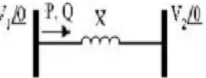
[image:2.595.56.202.218.273.2]A mathematical expression for reactive power flow using a simplified model of the system as shown in fig1
Fig 1: Reactive power transmission line model
Qr =
Where Qr is the reactive power, Vs and Vr are sending end and receiving end voltage, cos is power angle, and X is line reactance. If power angle is small cos and hence the above equations for Qr and Qs are rewritten as-
Qr = ………….4
Qs = ………5
From equation 4 and 5 it is clear that reactive power flow depends on difference between voltage magnitudes and it flow from higher voltage to lower voltage. Decrease reactive power loss, when we minimum reactive power transfer in transmission line and operating voltage should be high. High operating voltage minimizes the reactive power loss it helps maintain voltage stability.
4. FLEXIBLE AC TRANSMISSION SYSTEMS (FACTS):
A day by day increasing demand of electric power, this transmission networks are found to be weak which results in poor quality of supply. Also we want to increase the power transfer capability of transmission line. After lot of research a new technology is developed which increase the efficiency of power transmissions system. This technology is known as flexible AC transmission systems (FACTS).Roughly two decades prior, adaptable AC transmission frameworks (FACTS) were presented. The flexible ac transmission system (FACTS) is defined by IEEE as “a power electronic based framework and other static
equipments that provide control of one or more ac-transmission framework parameters to enhance controllability and increase power transfer capability”, and can be utilized for power-flow control. A FACTS incorporates power electronics and controllers to enhance power system controllability and increase transfer capability. The main objective of FACTS device is to replace the existing slow acting mechanical device.
4.1 NEED OF A FACTS DEVICE-
1 To increase the power transfer capability in transmission system.
2 To increase the power system stability
3 To control the power flow in desired transmission route. 4 To provide dynamic stabilization enhancement for the transmission system.
4.2 The FACTS device can be classified as –
1) Shunt connected controllers 2) Series connected controllers 3) Combined series-series controllers 4) Combined shunt-series controllers”
Shunt connected controller:
Figure 2: series controller
A shunt device is the one that is connected between the grid and the ground. These devices basically generate or absorb reactive power at connection point and thus control voltage magnitude. There are three such types of devices: “switched shunt inductor and capacitor devices, static VAR compensator (SVC) and static synchronous compensator (STATCOM)”.
Series connected controller:
© 2016, IRJET | Impact Factor value: 4.45 | ISO 9001:2008 Certified Journal
| Page 2095
A series device is connected in series with the line tochange (reduce or increase) the line impedance. A Thyristor controlled series capacitor (TCSC), Thyristor controlled series reactor (TCSR), A Thyristor switched series capacitor (TSSC), and the static synchronous series compensator (SSSC) are series facts device.
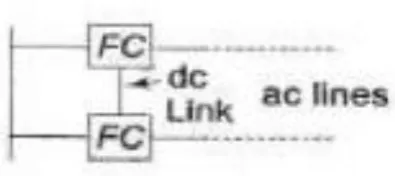
[image:3.595.36.234.222.310.2]Combined series-series controller:
Figure 4: Combined series-series controller
DSSC (distributed static series compensator) is the example of combined series-series controller. The DSSC is basically a distributed SSSC, with same functions as SSSC but at lower cost and improved reliability. It uses a number of low power rating units in place of one large rating converter.
Combined shunt series controller:
[image:3.595.317.563.322.483.2]These devices also called hybrid device. It is combination of series and shunt controller. E.g. is inter-line power flow controller (IPFC), Unified power flow controller (UPFC), DPFC (distributed power flow controller).
Figure 5: Combined shunt series controller
These FACTS device improve the power system voltage stability. The most advance device in this FACTS family is DPFC facts device is used for stability improvement.
5. Distributed power flow controller (DPFC):
The combined FACTS device, specifically UPFC and IPFC have superior control capabilities. However, they are not widely used commercially due to their cost and failure
problems. If number of components is reduced, reliability increases but this option is not feasible because of UPFC’s complex structure. The components with higher rating can be used to reduce failure rate but this again increases the initial investment.UPFC have most progressive control capacity.
[image:3.595.39.273.527.627.2]This paper introduce the new FACTS device, is called DPFC. The DPFC is derived from the unified power-flow controller (UPFC).The DPFC contains a shunt and number of series connected converters. Basically shunt converter resembles a STATCOM and series converter uses the DSSC method, i.e., using a number of 1-ph converters in place of one high rated 3-ph converter. Every converter is independent & contains a DC capacitor to power itself as shown in fig.6
Figure 6: DPFC configuration
DPFC is derived from UPFC:
Two approaches are applied to the UPFC
[image:3.595.310.552.552.722.2]© 2016, IRJET | Impact Factor value: 4.45 | ISO 9001:2008 Certified Journal
| Page 2096
Eliminating the common dc link of the UPFC
Within the DPFC, there is a common connection between the ac terminals of the shunt and the series converters, in the transmission line. Therefore, it is possible to exchange the active power from the ac terminals of the converters. The method is based on the power theory of non sinusoidal components. as stated in the Fourier analysis, a non sinusoidal voltage and current can be expressed by the sum of sinusoidal functions in other frequencies with other amplitudes. The active power resulting from this non sinusoidal voltage and current is expressed by the mean value of the product of voltage and current. Since the integrals of all the cross product of all terms with different frequencies are zero, the active power can be expressed by
P =
Where Viand Ii are the voltage and current at the ith harmonic frequency respectively, and φi is the corresponding angle between the voltage and current.
Distributed series converter:
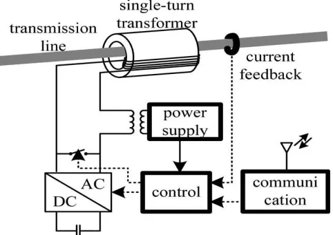
The D-FACTS is a result of the series-connected FACTS, which can reduce the total cost and increase the reliability of the series FACTS device. The idea of the D-FACTS is to use a multiple number of controllers with low rating instead of one large rated controller. The small controller is a single-phase converter connected to transmission lines by a single-turn transformer. The converters are suspended hanging in the balance so that no immoderate high-voltage detachment is required. The single-turn transformer utilizes the transmission line as the auxiliary winding, embedding Controllable impedance into the line straightforwardly. Every D-FACT module is self-powered from the line and controlled remotely by remote or electrical cable correspondence (appeared in Fig. 8). The structure of the D-FACTS results in minimal effort and high unwavering quality. As D-FACTS units are single-stage device drifting on lines, high-voltage detachments between stages are maintained a strategic distance from. The unit can without much of a stretch be supplied at any transmission-voltage level, since it doesn't require supporting stage ground detachment. The force and voltage rating of every unit is generally low. Further, the units are cinched on transmission lines, and in this manner, no area is required. The D-FACTS provides an uninterrupted
[image:4.612.312.553.151.321.2]operation when a single module failure, therefore giving a much higher reliability than other FACTS devices.
Fig 8. D-FACTS unit configuration
5.2 DPFC CONTROL
There are three types of controllers as shown in fig 9.
1. Central control:
The work of this control is to produce the reference signals. According to system requirement, it provides reference voltage signal and reactive current signal. All these reference signals concerns the fundamental frequency.
2. Series control:
A series control is there with each series converter. It supports the converters capacitor voltage by using harmonic frequency components. It also generates series voltage at fundamental frequency as required by the central control.
3. Shunt control:
© 2016, IRJET | Impact Factor value: 4.45 | ISO 9001:2008 Certified Journal
| Page 2097
Fig 9 DPFC control block diagram6. SIMULATION AND RESULT:
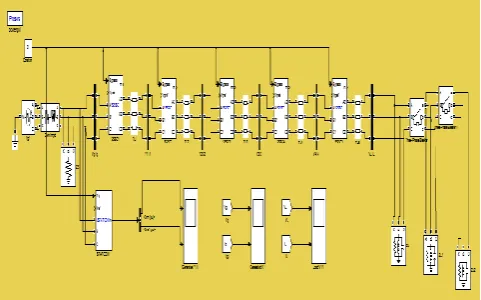
[image:5.595.310.558.238.435.2]In this paper DPFC based transmission line model is developed (shown in fig 10) to know the compensation effects of DPFC controller, which is new to FACTS family. DPFC is mutant from UPFC and DSSC, from for merit eliminates common DC links and from later one it take side a of D-FACTS series controller by combining the set of properties we get DPFC controller model.
Fig 10: DPFC Controller, MATLAB/SIMULINK model
Fig11 DPFC, GA based MATLAB/SIMULINK model
Detail of the SSSC and STATCOM values are mentioned in Table 1, Table 2 and Table 3, here description of developed model is being done. In this paper work genetic algorithm based controller for DPFC is developed toimprove power system stability. For this DPFC controller with Genetic Algorithm based control is from all other units and are controlled and monitored by the genetic algorithm at the center. Shown in Figure 11.
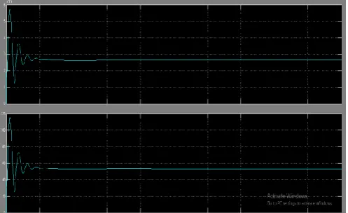
Fig 12 Voltage& current comparison plot at generator bus without GA
[image:5.595.36.277.408.558.2]In the Fig12 and fig 13 voltage & current comparison plot are shown the generator bus voltage fluctuations are reduced and system become more stable by compensated controllers .
[image:5.595.36.275.600.748.2]© 2016, IRJET | Impact Factor value: 4.45 | ISO 9001:2008 Certified Journal
| Page 2098
Fig 14 Voltage & current comparison plot at load bus withoutGA
The Fig 14 & fig 15 expresses that the voltage to be injected is reduced from 490 kv to 290 kv which protects the system from achieving leading power factor and conclusively improves the voltage profile and regulation through STATCOM. Also power enhancement is achieved from the series FACT devices. when voltage reduces the current increases due to short-circuit but here in this case with decrease in voltage current also decreases decreasing reactive power compensation, the current reduces from 90 amp to 55 amps.
Fig 15 voltage & Current comparison plot at load bus with GA
Fig 16 Reactive power compensation
At the generator side measures the reactive power to be injected by the FACT in the form of voltage control. In the figure mentioned below it can be seen that there is an exponential rise in Q (reactive power) without genetic algorithm control, while with the genetic algorithm control there is an exponential decay in the reactive power.
This decline of reactive power decreases the injected voltage from 550kv to 270KV at load end as shown in Figure 16
7. CONCLUSION
The aim of the research is to use the genetic algorithm as Centralized controller for the improvement of the performance of DPFC & the simulation results shows that the proposed algorithm works well and improves the load regulation and fluctuations. The work can be easily carried properly even with failure of one of the series converters.
8. Future scope:
It is aimed that the future of power system network will not be unidirectional else it will be bidirectional depending upon the consumption of power .so the need of distributed power system is nessacary in the formation of smart grid and electric vehicles system which is the near stable future for power system. Hence these places will need more optimization in their work were work can be ahead carried above the approaches of genetic algorithms.
[image:6.595.36.290.102.245.2]Simulation model parameter:
Table 1 transmission line parameter
[image:6.595.37.286.437.589.2]
Table 2 SSSC parameter Shivendra singh Thakur is an asst. Prof. in Dept. of electrical
[image:6.595.306.548.500.722.2]© 2016, IRJET | Impact Factor value: 4.45 | ISO 9001:2008 Certified Journal
| Page 2099
Table 3 STATCOM parameterREFERENCES
1) Zhihui Yuan, HaanSjoerd W. H. de, Ferreira Jan Braham, and CvoricDalibor, “A FACTS Device: Distributed Power-Flow Controller (DPFC),” IEEE Trans. Power Electron., vol. 25, no. 10, Oct.2010.
2)Naghabhushan , manjunath G kadashetti, “distributed power flow controller: Modified UPFC with eliminating
common DC link,” IJETT-volume 16 number 8 – oct 2014 3)Tang Ye, Hu Wei, Huang Yang, Xu Fei, Min Rui,
“Coordinated control of multi-FACTS to enhance the small disturbance stability of the power system”, IEEE PES ISGT
ASIA 2012. 4)Yuan Z., Haan S.W.H. de, Ferreira J.A., “Control Scheme to
Improve DPFC Performance during Series Converter
Failures”, in proc. IEEE 2010. 5)V.Anwesh kumar , G.Madhusdhana Rao,B.V.sankar ram,
“Analysis of a neural network based distributed power flow controller (DPFC) for power system stability” International journal of advanced trends in computer science and
engineering, vol. 3 , no. 1, pages :464-470 (2014) 6)C.L. whadhwha book, “power system voltage stability and
reactive power flow”.
7)Kumar Arun, and G. Priya, “Power System Stability Enhancement using FACTS Controllers,” in Proc. IEEE
Industrial Electronics 2012. 8)Singh B., Saha R., Chandra A., and Al-Haddad K. “Static
synchronous compensators (STATCOM): a review”. Power Electronics, IET, 2009.
9) Zhihui Y., Haan S. W. H. de, and Ferreira B, “Dpfc control during shunt converter failure,” in Proc. IEEE Energy Convers.
Congr. Expo. (ECCE), pp. 2727–2732, 2009.
BIOGRAPHIES
Nivedita Bajpayi is currently a master’s scholar in electrical machine and Drives form SATI college Vidisha. I had completed my B-tech in electrical and electronics engineering from IITM Gwalior (M.P).
Shivendra singh Thakur is an asst. Prof. in Dept. of electrical
engineering, SATI college Vidisha. He has a teaching experience 16 years and published many research papers on multilevel inverters. Boost converters, speed control of PMBLDC motors and so on….
Shivendra singh Thakur is an asst. Prof. in Dept. of electrical