Performance Comparison between Two Electrodes and Three
Electrodes MEMS Capacitive Switch using Architect
Coventorware
Norhaslinawati Ramli
1, Othman Sidek
2,*1
Universiti Kuala Lumpur, British Malaysian Institute, Gombak, Selangor, MALAYSIA 2
Universiti Sains Malaysia, Kampus Kejuruteraan, Nibong Tebal, Pulau Pinang, MALAYSIA
Received 1 November 2013; received in revised form 7 January 2014; available online 30 January 2014
1.
Introduction
MEMS (micro-electromechanical-system) structure is a device in a micro-scale dimension that integrates a sensor, actuator, electronics circuitries and mechanical element. It can be fabricated using micro-machining technology either surface or bulk micromachining which has been extended from conventional IC (integrated circuit) batch processing technique. Since early 1980s, MEMS devices have been used in many area including automotive, mobile communication, biology, chemistry and etc. MEMS devices such as airbag accelerometers have been used in cars, micromirrors used for projectors and micronozzels in inkjet printers [1]. In the future, MEMS devices are expected to have a great impact on biotechnology, military, aerospace and wireless communication and some other technologies.
Design and fabrication of MEMS specifically for RF integrated circuit was called as RF MEMS. RF MEMS are small mechanical device used in RF and microwave frequency circuit. RF MEMS can be divided into three categories that are RF MEMS device (switch, inductor, and varactor), RF MEMS circuit (phase shifter, filter and
oscillator) and RF MEMS systems (phase array antenna, switch matrix, cell phone and pager). RF MEMS switch is a specific micromechanical switch that is designed to operate at RF to milimeterwave frequency (0.1 – 100GHz). It is a device that uses mechanical movement to achieve a short circuit or open circuit in the RF transmission line [2]. Nowadays, it has been tremendously being used to replace the other RF switches which are p-i-n diode and field effect transistor due to its capability to maintaingreat RF performance such as high isolation and very low insertion loss as the frequency increase.
However, one of the drawbacks of RF MEMS switch is it has a high actuation voltage around 20V-80Vwhich is higher than standard operation voltage of CMOS IC, normally 5V or less. Since it is not well-suited with the other CMOS IC, therefore the integration of MEMS with CMOS would be complicated and intricate in a single chip. This problem can be solved by reducing the actuation voltage by using a low spring constant structure which later will cause another problem that is stiction. Stiction happened when a MEMS switch gets stuck in the down-state position [3]. Stiction can be solved by Abstract: This paper presents the electromechanical and RF performance comparison between two electrodes and three electrodes MEMS capacitive switch using Architect Coventorware. The important of this study is to react to the industries in providing low actuation voltage MEMS capacitive switches with low loss and high isolation and make it possible to be integrated with CMOS circuit. MEMS capacitive switches with three different support structure namely fixed-fixed beam, single meander and double meander have been designed and simulated in both standard and proposed structure. A standard switch consists of two parallel electrodes and a proposed switch consists of three parallel electrodes. Designing using schematic capture begin by selecting the suitable component from electromechanical library to represent membrane, support structure, anchor, bottom electrode, top electrode, ground, transmission line-in and transmission line-out. The schematic diagram has been simulated and translated to 2D layout and 3D model for physical verification. The electromechanical analysis has been carried out using DC Transfer Analysis. In DC Transfer Analysis, the value of pull-in voltage, up-state and down-state capacitance can be attained. In Small Signal Frequency Analysis the value of resonant frequency is obtained. The measurement of RF performance was done using RF Electrical Analysis. Simulation result shows the pull-in voltage for all proposed design has been reduced 40%-50% as compared to their standard counterpart. While the result for other performance including capacitances for three electrodes switch has almost same value as two electrodes structure. The switch indicates low insertion loss (<-0.4db) in the up-state position and high isolation (>-26dB) in the down-state position. This concludes that the additional top membrane does maintain the good electromechanical and RF performance of MEMS capacitive switch.
providing enough return force using a stiff structure. However, a stiff structure will affect the insertion loss of the switch. A better switch should have a low insertion loss. For that reason, there was a conflict between the requirement for low actuation voltage and low loss operation device. Thus, the optimization of the switch is the trade-off between RF and electromechanical parameters [4].
Hence this research is intentionally to design and simulate a new structure of RF MEMS capacitive switch with the purpose of reducing the actuation voltage, overcome the stiction problem and make the integration of MEMS and CMOS IC possible.
2.
Literature Review
Since early 1990s, numerous structures of low voltage RF MEMS switch with different materials [5], [6], [7], [8], [9] new process flow [10], [11] and a variety of architectures [12], [13], [14], [15], [16], [17], [18], [19], [20] have been designed. Nowadays, MEMS switch advancement activities are still in growth at the leading companies, universities and research institution worldwide.
3.
Switch Structure
RF MEMS switch can be categorized by electronics configuration (series shunt), actuation mechanism (electrostatic, thermal, magnetic, piezoelectric), contact mechanism (capacitive, metal-to-metal) and anchor mechanism (cantilever, fixed-fixed beam). Capacitive switch is a device which consists of capacitors with a gap and a voltage is applied between them as shown in Fig. 1. Changing the gap between the capacitors hence will vary the capacitance value.
Fig. 1 Configuration of Capacitive Switch
A typical capacitive switch as shown in Fig. 2 consists of CPW (Coplanar Waveguide) transmission lines, a fixed-fixed membrane suspended from the anchor, over a bottom actuation electrode (part of CPW) insulated by dielectric layer. This dielectric layer will help to prevent the electric shock between two conductors. It also will provide low impedance path for the RF signal [21].
Fig.2 A shunt capacitive switch in the up-state position
When the switch is not actuated, the signal can go through the path. A low capacitance with the value in range of tens femtoFarads exists between the membrane and the bottom electrode. The device will be in the ‘OFF’ state. Equation (1) can be used to calculate the off-state capacitance.
(
g A) (
g A)
C
d d off
0 0/
/ 1
ε
ε +
= (1)
Where gd is the dielectric layer, g0 is the gap between the membrane and the dielectric layer, εd and ε0 are the dielectric constants of dielectric material and air, respectively, and A is the actuation area.
Fig.3 A shunt capacitive switch in the down-state position
When the DC voltage is applied between the membrane and the actuation electrode, the electrostatic force will be created to pull the membrane down. Fig. 3 represents a diagram of RF MEMS Capacitive switch during down-state position. As the membrane collapsed, it thus makes a contact with the dielectric layer. For a capacitive switch where the gap is zero, an outstanding contact must be achieved between the membrane and the dielectric layer. The device now is in the ‘ON’ state and its capacitance value has increased. Typical capacitance values for this position are 3-4pF [2].
The on-state capacitance can be calculated by using the following equation:
d d on
g A
C =ε (2)
wW kg Vp 0 3 0 27 8 ε
= (3)
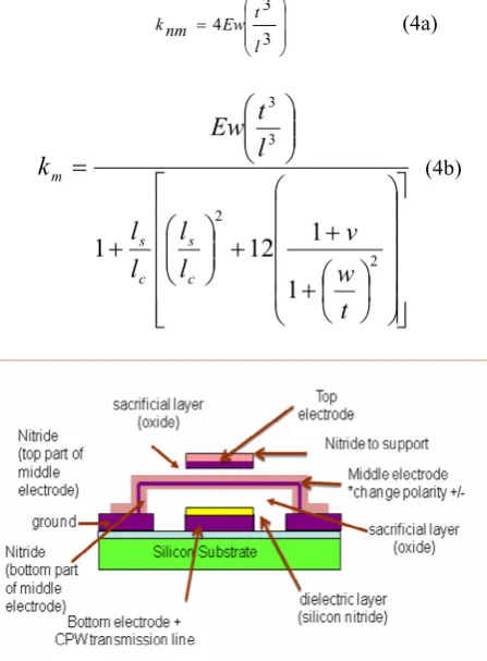
where k is the effective spring constant of the moving structure in z-direction, g0 is the initial gap height between the membrane and the electrode, ε0 is the free-space permittivity, and w is the width of the membrane and W is the width of the pull-down electrode. The spring constant for non-meander and meander structure are given by (4a) and (4b) respectively as below:
= 3 3 4 l t Ew nm
k (4a)
+
+
+
+
=
2 2 3 31
1
12
1
t
w
v
l
l
l
l
l
t
Ew
k
c s c sm (4b)
Fig.4 Three Electrodes Structure Switch
Fig. 4 shows the new switch topology that has been proposed in this research. The basic structure is similar to standard switch. However, instead of using two parallel electrodes, the proposed switch will have three parallel electrodes. The top and bottom electrode will be maintained at a constant potential with different value while the middle electrode is movable. Since one and half electrostatic forces acted on the membrane, so the switch is expected to have a lower actuation voltage. As mention before, when DC voltage was applied between two parallel electrodes, the electrostatic force will be created and it can be calculated by using equation (5) as shown below: 2 2 0 2 1 g wWV Fe=− ε (5)
where g is the gap height between membrane and the electrode, ε0 is the free-space permittivity, and w is the
width of the membrane, W is the width of the pull-down electrode and V is the voltage applied between two electrodes. On the other hand, due to spring constant of the switch, there is another force exists called as pull-up force. When the values of this force are same, the equilibrium state will be achieved.
Thus
F= ( 0 )
2 2 0 2 1 g g k g wWV − =
− ε (6)
where g0 is initial bridge height.
Therefore, in these three parallel structures one and half of electrostatic force is equal to one pull-up force, hence will produce a new pull-in voltage given by equation (7):
wW kg Vproposed 0 3 0 ) 3 ( 27 8 ε
= (7)
This equation is applicable to calculate the pull-in voltage for all structures by using respective spring constant, k.
4.
Coplanar Waveguide Design
Designing the RF MEMS shunt switch includes designing a coplanar waveguide (CPW) transmission line with characteristic impedance of 50Ω. CPW consists of a center conductor on a substrate with two grounds located parallel to it as shown in Fig.5 below:
Fig.5 Coplanar waveguide transmission lines
The characteristic impedance of CPW can be calculated using the formula given below:
(
)
1 1 1 2 ln 2 1 2 30 0 − − + + = k k r Z ε π (8) where w s s k 2 += with s = center strip width, w = slot width and εr = relative dielectric constant of the substrate.
An equation for the effective relative dielectric constant
ε
re[23] in equation (9) is given as:(
)
+ − + − + + + = 100 25 . 0 1 . 0 1 7 . 0 04 . 0 75 . 1 log 785 . 1 tanh 2 1 k r k h kw w h r re ε εThe characteristic impedance also can be calculated by using this formula:
jwC G
jwL R Z
+ + =
0 (10)
where R = resistance per unit length
L = inductance per unit length G = conductance per unit length C = capacitance per unit length
5.
Switch Design Methodology
5.1 Design Part
Three different structures that have been designed and simulated were shown in Fig. 6(a), 6(b) and 6(c).
Fig.6(a) Switch with Fixed-Fixed Beam Support Structure
Fig.6(b) Switch with Single Meander Support Structure
Fig.6(c) Switch with Double Meander Support Structure
The spring constant for fixed-fixed beam was obtained from equation (4a) while the spring constant for single and double meander was specified as (11) and (12) below:
( )
nm mnm m m
k
k
k
k
k
2
+
=
(11)
nm m
nm m m
k
k
k
k
k
+
=
(12)
Table 1: Switch Physical Dimension
To create a switch with low pull-in voltage, all optimization factors including beam width, beam thickness, beam length and actuation area have been considered during calculation. Table 1 shows the best switch physical dimension for fixed-fixed beam, single meander and double meander support structures obtained from theoretical calculation. .
5.2
Simulation Part
Sophisticated well-known MEMS software, Architect Coventorware has been used for simulation. Designing using this software starts by inserting the material properties parameters such as density, thermal conductivity and dielectric in the material properties database. The materials used in this research are silicon for substrate, aluminium for CPW and membrane, silicon nitride for dielectric and silicon dioxide for sacrificial layer. Fig.7 shows the properties of Aluminum used to design the switch.
Fig.7 Material Properties Database for Aluminum Physical Dimension
Fixed-Fixed Beam
Single Meander
Double Meander
Beam Length, l (µm) 300 - - Beam Length, ls
(µm)
- 100 50
Beam Length, lc (µm)
- 50 50
Beam Thickness, t (µm)
1.7 1.7 1.7
Beam Width, w (µm) 5 5 5
Electrode width, W1=W2 (µm)
120 120 120
Air gap, g0 (µm) 3 3 3
Modulus Young, E (GPa)
70 70 70
Spring constant, k 0.2547 0.1337 1.4701 Pull-In Voltage, Vp
(V)
Next, the simulation process was stated in the process editor. Three basic steps involved are deposition, patterning and etching. The process flow for two electrodes structure begins with the deposition of oxide and aluminum above the silicon substrate, followed by silicon nitride and then once again aluminum. However, the process flow for three electrodes structure requires some modification with the addition of silicon nitride and aluminium for the top membrane. Fig. 8a and 8b show the simulation process for two and three electrodes structure.
Fig.8a Simulation process flow for two electrodes
Fig.8b Simulation process flow for three electrodes
The most important step is to choose the appropriate component provided in the electromechanical library to represent anchor, membrane, electrodes, support structure, ground and transmission line as shown in Fig. 9 below.
Fig. 9 Parametric Libraries Window
Fig. 10(a), 10(b) and 10(c) show the schematic diagram of proposed switch for fixed-fixed beam, single meander and double meander support structure.
Fig.10(a) Schematic Diagram of Three Electrodes Fixed-Fixed Beam Support Structure
Fig.10(b) Schematic Diagram of Three Electrodes Single Meander Support Structure
Fig.10(c) Schematic Diagram of Three Electrodes Double Meander Support Structure
Fig.10 Detailed Input Parameter for Rigid Plate Fixed Electrode
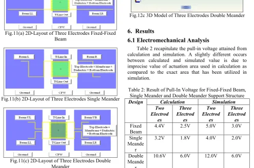
The schematic diagram that has been designed will be simulated and the result will be plotted and analyse. In addition, physical verification can be observed through 2D Layout and 3D Model. Fig. 11(a), 11(b) and 11(c) show the 2D-Layout of proposed switch for fixed-fixed beam, single meander and double meander support structure.
Fig.11(a) 2D-Layout of Three Electrodes Fixed-Fixed Beam
Fig.11(b) 2D-Layout of Three Electrodes Single Meander
Fig.11(c) 2D-Layout of Three Electrodes Double Meander
Fig. 12(a), 12(b) and 12(c) show the 3D Model of proposed switch for fixed-fixed beam, single meander and double meander support structure.
Fig.12a 3D Model of Three Electrodes Fixed-Fixed Beam
Fig.12b 3D Model of Three Electrodes Single Meander
Fig.12c 3D Model of Three Electrodes Double Meander
6. Results
6.1 Electromechanical Analysis
Table 2 recapitulate the pull-in voltage attained from calculation and simulation. A slightly different occurs between calculated and simulated value is due to imprecise value of actuation area used in calculation as compared to the exact area that has been utilized in simulation.
Table 2: Result of Pull-In Voltage for Fixed-Fixed Beam, Single Meander and Double Meander Support Structure
Calculation Simulation
Design
Two Electrod
es
Three Electrod
es
Two Electrod
es
Three Electrod
es Fixed
Beam
4.4V 2.5V 5.0V 3.0V
Single Meande
r
3.2V 1.8V 4.0V 2.0V
Double Meande
r
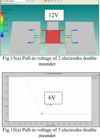
10.6V 6.0V 12.0V 6.0V
proposed structure has been reduced half compared to the standard structure.
Fig.13(a) Pull-in voltage of 2 electrodes fixed-fixed beam
Fig.13(a) Pull-in voltage of 3 electrodes fixed-fixed beam
Fig.14(a) Pull-in voltage of 2 electrodes single meander
Fig.14(a) Pull-in voltage of 3 electrodes single meander
Fig.15(a) Pull-in voltage of 2 electrodes double meander
Fig.15(a) Pull-in voltage of 3 electrodes double meander
Table 3 summarizes the up-state capacitance while Table 4 presents the down-state capacitance obtained from calculation and simulation. Both two electrodes and three electrodes switch shared the same value of up-state and down-state capacitance in calculation with the assumption both structures have the same initial height, 3µm.
Table 3: Result of Up-State Capacitance For Fixed-Fixed Beam, Single Meander and Double Meander Support
Structure
Calculation Simulation
Design
Two Electrod
es
Three Electrod
es
Two Electrod
es
Three Electrod
es Fixed
Beam
38.4fF 38.4fF 29.9fF 39.9fF
Single Meande
r
38.4fF 38.4fF 29.9fF 43.4fF
Double Meande
r
38.4fF 38.4fF 29.9fF 41.7fF
Table 4: Result of Down-State Capacitance For Fixed-Fixed Beam, Single Meander and Double Meander
Support Structure
Calculation Simulation
Design
Two Electrod
es
Three Electrod
es
Two Electrod
es
Three Electrod
es Fixed
Beam
3.4pF 3.4pF 3.45pF 3.38pF
Single Meande
3.4pF 3.4pF 3.34pF 3.34pF
5V
3V
4V
2V
r Double Meande
r
3.4pF 3.4pF 3.62pF 3.48pF
Fig.16(a) Simulated up-state and down-state capacitance for two electrodes fixed-fixed beam structure
Fig.16(b) Simulated up-state and down-state capacitance for three electrodes fixed-fixed beam structure
Fig.17(a) Simulated up-state and down-state capacitance for two electrodes single meander structure
Fig.17(b) Simulated up-state and down-state capacitance for three electrodes single meander structure
Fig.18(a) Simulated up-state and down-state capacitance for two electrodes double meander structure
Fig.18(b) Simulated up-state and down-state capacitance for three electrodes double meander structure
Fig.16(a), 16(b), 17(a), 17(b), 18(a) and 18(b) presents the simulation result of up-state and down-state capacitance of two and three electrodes structure for fixed-fixed beam, single meander and double meander structure respectively. The up-state capacitance was measured when the switch in initial height, 3µm and the down-state capacitance was measured at pull-down voltage value.
An electromechanical analysis should include the analysis of the resonant frequency. It can be calculated by can be calculated by using the formula [22] given below:
( )( )( )
( )( )
A
w
t
E
L
a
f
rρ
π
12
2
3 2
2
=
Where t is the beam thickness, beam width, E is Moduluis Young, ρ is density, A is area, L is beam length and a is 4.73.
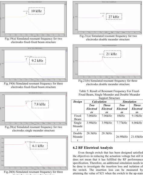
The simulation of resonant frequency for both two electrodes and three electrodes structure was carried out using Small Signal Frequency Analysis as shown in Fig. 19(a), 19(b), 20(a), 20(b), 21(a) and 21(b) below. The result shows that both switches shared almost equal resonant frequency value with small different percentage.
39.9fF
3.38pF
29.9fF
3.3419fF
29.94fF
3.4516pF
29.94f
3.618pF
41.7fF
3.48pF
43.4fF
Fig.19(a) Simulated resonant frequency for two electrodes fixed-fixed beam structure
Fig.19(b) Simulated resonant frequency for three electrodes fixed-fixed beam structure
Fig.20(a) Simulated resonant frequency for two electrodes single meander structure
Fig.20(b) Simulated resonant frequency for three electrodes single meander structure
Fig.21(a) Simulated resonant frequency for two electrodes double meander structure
Fig.21(b) Simulated resonant frequency for three electrodes double meander structure
Table 5: Result of Resonant Frequency For Fixed-Fixed Beam, Single Meander and Double Meander
Support Structure
Calculation Simulation
Design
Two Electrod
es
Three Electrod
es
Two Electrod
es
Three Electrod
es Fixed
Beam
7.06kHz 7.06kHz 10kHz 9.18kHz
Single Meande
r
3.98kHz 3.98kHz 7.77kHz 6.06kHz
Double Meande
r
28.3kHz 28.3kHz
26.98kHz 21.03kHz
6.2
RF Electrical Analysis
Even though switch that has been designed satisfied the objectives in reducing the actuation voltage but still it does not mean that it has fulfilled the RF performance specification. Therefore, an additional simulation needs to be done to investigate the insertion loss and isolation of the switch. The insertion loss can be measured by attaining the value of S21 when the switch in the up-state position while isolation can be measured by obtaining the value of S21 when the switch in the down-state position.
Figure 22 (a) shows the RF performance for proposed fixed-fixed beam switch during up-state position with the value of insertion loss (S21) at 40GHz is -0.29dB and return loss (S11) at 40GHz is -11.8dB.
6.1 kHz
27 kHz
21 kHz
Fig. 22(a) RF Performance when switch in the up-state (fixed-fixed beam switch with 3 electrodes)
Figure 22 (b) shows the RF performance for proposed single meander switch during up-state position with the value of insertion loss (S21) at 40GHz is -0.31dB and return loss (S11) at 40GHz is -11.6dB.
Fig. 22(b) RF Performance when switch in the up-state (single meander switch with 3 electrodes)
Figure 22 (c) shows the RF performance for proposed double meander switch during up-state position with the value of insertion loss (S21) at 40GHz is -0.20dB and return loss (S11) at 40GHz is -14.8dB.
Fig. 22(c) RF Performance when switch in the up-state (double meander switch with 3 electrodes)
Figure 23 (a) shows the RF performance for proposed fixed-fixed beam switch during down-state position with the value of insertion loss (S21) at 40GHz is -26.69dB and return loss (S11) at 40GHz is -0.11dB.
Fig. 23(a) RF Performance when switch in the down-state (fixed-fixed beam switch with 3 electrodes)
Figure 23 (b) shows the RF performance for proposed single meander switch during down-state position with the value of insertion loss (S21) at 40GHz is -26.69dB and return loss (S11) at 40GHz is -0.11dB.
Fig. 23(b) RF Performance when switch in the down-state (single meander switch with 3 electrodes)
Figure 23 (c) shows the RF performance for proposed double meander switch during down-state position with the value of insertion loss (S21) at 40GHz is -27.23dB and return loss (S11) at 40GHz is -0.22dB.
Fig. 23(c) RF Performance when switch in the down-state (double meander switch with 3 electrodes)
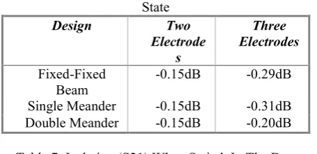
Table 6 presents the simulated value of insertion loss for both two electrodes and three electrodes switch in the up-state position. While Table 7 presents the simulated value of isolation for both structures in the down-state position. The results show that the loss and isolation for three electrodes switch almost equal to two electrodes switch. This indicates that the addition of top electrode does not effect the RF performance of the switch.
S
21= -0.29dB
S
21= -26.69dB
S
21= -27.234dB
S
21= -0.2032dB
S
21= -26.694dB
Table 6: Insertion Loss (S21) When Switch In The Up-State
Design Two
Electrode s
Three Electrodes
Fixed-Fixed Beam
-0.15dB -0.29dB
Single Meander -0.15dB -0.31dB Double Meander -0.15dB -0.20dB
Table 7: Isolation (S21) When Switch In The Down-State
Design Two
Electrode s
Three Electrodes
Fixed-Fixed Beam
-26.5dB -26.7dB
Single Meander -26.7dB -26.7dB Double Meander -26.9dB -27.2dB
Conclusion
MEMS Capacitive switches with three different support structure namely fixed-fixed beam, single meander and double meander have been designed and simulated in both standard and proposed structure using Architect Coventorware. A standard switch consists of two parallel electrodes while proposed switch consists of three parallel electrodes. The proposed switch shows a reduction in an actuation voltage compared to its standard counterpart. Once the switch had been designed using schematic capture method, then it will be viewed in 2D-Layout and 3D Model for physical verification. Hence, the switch performance such as pull-in voltage, up-state capacitance, down-state capacitance and resonant frequency will be quantified and analyzed. The insertion loss and isolation also have been measured to ensure that the switch has fulfilled the RF specification. Simulation results show that the electromechanical and RF performance of three electrodes switches is almost equal to two electrodes switches with small different value. This concludes that additional top membrane does help to reduce the pull-in voltage of the switch in order to make it compatible with other CMOS circuitries and at the same time maintain the great performance of MEMS capacitive switch.
References
[1] G. M. Rebeiz, "RF MEMS Switches: Status of Technology," in The 12 th International Conference On Solid State Sensors, Actuators and Microsystems, Boston, 2003, pp. 1726-1729.
[2] G. M. Rebeiz, RF MEMS Theory, Design and Technology: John Wiley and Sons, 2003.
[3] MEMS for Microwaves (2012) [Online]. [Accessed 5th February 2012]. Available from World Wide
Web:http://www.microwaves101.com/encyclopedia/
MEMS2.cfm#ohmic/
[4] J. McKillop, "MEMS Switch Challenges," in Microwave Magazine. vol. 50, 2007.
[5] B. B. Devarajan, S.K; and Ayazi, F., "Low Cost Low Actuation Voltage Copper RF MEMS Switches," pp. 1225-1228, 2002.
[6] G. P. Li, "On the Design and Fabrication of Electrostatic RF MEMS Switches," Dept. of Electrical and Computer Engineering, California University.
[7] F. M. Guo, Z. Q. Zhu, Y. F. Long, W. M. Wang, S. Z. Zhu, Z. S. Lai, N. Li, G. Q. Yang and W. Lu, "Study on low voltage actuated MEMS rf capacitive switches," Sensors and Actuators A: Physical, vol. 108, pp. 128-133, 2003.
[8] R. Chan, R. Lesnick, D. Becher, and F. Milton, "Low-actuation voltage RF MEMS shunt switch with cold switching lifetime of seven billion cycles," Microelectromechanical Systems, Journal of, vol. 12, pp. 713-719, 2003.
[9] L. D. Ching, J. P. Hsuan, C. L. Mao, and C. W. Chyan, "Design and Fabrication of RF MEMS switch by the CMOS Process," Tamkang Journal of Science and Engineering, vol. 8, No.3, pp. 197-202, 2005. [10] S. P. Pacheco, L. P. B. Katehi, and C. T. C. Nguyen,
"Design of low actuation voltage RF MEMS switch," in Microwave Symposium Digest, 2000 IEEE MTT-S International, 2000, pp. 165-168 vol.1.
[11] J. P. H. L. D. Ching, C.L. Mao and C.W. Chyan, "Design and Fabrication of RF MEMS switch by the CMOS Process," Tamkang Journal of Science and Engineering, vol. 8, No.3, pp. 197-202, 2005. [12] H. X. Zhang, Y. L. Hao, Z. Y. Xiao, D. M. Lou, N.
Finch, J. Marchetti, D. Keating, and V. Narashima, "Design of A Novel Bulk Micro-machined RF MEMS Switch," in In Proceedings of the International Conference on Micro And Nano Systems, Kunming, P.R. China., 2002.
[13]Y. L. Lai and L. H. Chang, "Design of Electrostatically Actuated MEMS Switches," Colloids and Surfaces A : Physicochem eng. Aspects 313 -314, pp. 469-473, 2008.
[14] M. Song, J. Yin, X. He, and Y. Wang, "Design and analysis of a novel low actuation voltage capacitive RF MEMS switches," in Nano/Micro Engineered and Molecular Systems, 2008. NEMS 2008. 3rd IEEE International Conference on, 2008, pp. 235-238.
[15] S. Touati, N. Lorphelin, A. Kanciurzewski, R. Robin, A. S. Rollier, O. Millet, and K. Segueni, "Low actuation voltage totally free flexible RF MEMS switch with antistiction system," in Design, Test, Integration and Packaging of MEMS/MOEMS, 2008. MEMS/MOEMS 2008. Symposium on, 2008, pp. 66-70.
[16] S. Kobayashi and H. K, "A Capacitive RF MEMS Shunt Switch " Murata Manufacturing Co. Ltd, Kyoto, Japan.
2008. 4th International Conference on, 2008, pp. 44-49.
[16] Y. Mafinejad, A. Z. Kouzani, K. Mafinezhad, and D. Izadi, "Design and simulation of a RF MEMS shunt switch for Ka and V bands and the impact of varying its geometrical parameters," in Circuits and Systems, 2009. MWSCAS '09. 52nd IEEE International Midwest Symposium on, 2009, pp. 823-826.
[19] S. Mingxin, Y. Jinghua, H. Xunjun, and W. Yue, "Design and analysis of a novel low actuation voltage capacitive RF MEMS switches," in Nano/Micro Engineered and Molecular Systems, 2008. NEMS 2008. 3rd IEEE International Conference on, 2008, pp. 235-238.
[20] S. Aghaei and E. Abbaspour-Sani, "A low voltage vertical comb RF MEMS switch," Microsystem Technologies, vol. 16, pp. 919-924.
[21] MEMS Switches (2012) [Online]. [Accessed 23th January 2012]. Available from World Wide
Web: http://www.newtechpapers.com/
[22] M. Brugger, J. Ludwig, D. MacGugan, and E. Salisbury, "Introduction to MEMS," University of Washington, Seattle, WA.