Study on the Composite ABS Control of Vehicles
with Four Electric Wheels
Chuanxue Song
State Key Laboratory of Automobile Dynamic Simulation/ Jilin University, Changchun, China [email protected]
Ji Wang and Liqiang Jin
State Key Laboratory of Automobile Dynamic Simulation/ Jilin University, Changchun, China [email protected]
Abstract—Proposed a composite ABS control method for vehicles with four electric wheels, and simulated the method. By analyzing the characteristic curves of the four in-wheel electric motors, and some typical braking force distribution methods of composite braking for EV, a braking force distribution method for four-electric-wheel EV is presented. The method combined the ideal braking force distribution curve, and considered the ECE braking regulations, so it can guarantee both the braking stability and the energy recovery. Furthermore, a composite ABS control method was proposed base on the braking force distribution method. The composite ABS control method is a control method that the electric motor ABS control works together with the hydraulic ABS control. Both of the two modes of ABS control logic were using logic threshold control method. The model of the electric-wheel vehicle were established with AMESim, and the model of the composite ABS controller were built with Simulink. Co-simulation were carried out. Through analysis, a number of parameters curves were obtained. It proves that the composite ABS control method for four-wheel electric vehicles can effectively control the slip rate, and ensure braking stability.
Index Terms—composite ABS control, electric motor ABS, hydraulic ABS, braking strength, braking force distribution, slip rate
I. INTRODUCTION
Pollution of automobile emission and energy issues have becoming the world-wide concerned problems. Energy conservation and emission reduction have becoming important development directions of automotive research. Promotion and application of electric vehicles can well alleviate this problem. Electric vehicles not only have the advantage of low emissions, but also the regenerative braking of electric vehicles can recycle part of braking energy, so they have energy-saving advantage. The electric motors of electric-wheel vehicles is installed in the wheel, and direct drive wheels. Because there don’t have mechanical transmissions between the power source and wheels, so the electric-wheel vehicles can simplify the transmission device, saving space and convenient to arrange. Meanwhile, due to the four wheels are directly controlled, therefore it's
easy to conduct differential, traction, braking and other precision controls which will improve the vehicle handling and stability[1-3]. So the development of electric-wheel vehicles can be the development direction of EV in the future. There are some differents in braking between EV and conventional vehicles. In conventional vehicle braking process, the vehicle’s kinetic energy is consumed by friction in the form of thermal energy, which will reduce the vehicle’s energy efficiency. When braking, the driving motors of EV are in the power generation mode, regenerative braking can be used to recycle energy[4-6]. In order to ensure energy recovery and braking performance, composite brake methods are often used. Some scholars studied the braking force distribution of composite brake system[7-8]. Yu and etc based on hybrid brake structural form and the classification of driver’s brake intent[9]. In this paper, we also use this method to coordinate regenerative braking and hydraulic braking. The current EV ABS is still using hydraulic ABS control of traditional vehicles . The hydraulic ABS system is complex. The control of hydraulic ABS is not very precise, and the delays are serious. By controlling the driving motor, the motors can rotating forward and reverse rapidly, the control method is simpler, the torque control is more precise, and the delay is relatively small, so the driving motors can be used to control brake ABS[10]. Chen and etc present a kind of regenerative braking system scheme based on a double SRM front brake[11-12]. The idea of hybrid ABS worths learning. The front wheels of their model can conduct electric motor ABS control in low braking strength, and conduct hydraulic ABS control in emergency braking. The electric motors they used are not driving motors, but the electric motor used in this paper are driving motors. In this paper, the composite ABS control combined the driving motor ABS control and hydraulic ABS control, all of the four wheels are independently composite braking controlled, electric motor ABS are used in low strength, and hydraulic ABS are used in heavy strength.
vehicle performance calculation. All of the four wheels have energy recovery, so when distribute the braking force between the front axle and the rear axle, both the safety and the energy recovery should be taken into account. When braking in low strength, electric motors are priority used. With the braking strength gradually increasing, the electric motor braking can not fully meet the demand of braking, so the hydraulic braking force gradually increase, so the system is in the area of composite braking. When the braking strength continues to increase, considering the brake safety, the hydraulic brake stability is relatively high, so electric motor braking gradually stop working, and finally hydraulic brake works alone. The composite ABS braking control is based on braking strength, and the relationship between electrical braking force and braking force requirements to convert ABS control modes. By using AMESim and Simulink we built a co-simulation model, and then simulated the model.
II. FOUR ELECTRIC-WHEEL VEHICLE BRAKING FORCE DISTRIBUTION
A. The axle’s braking force distribution
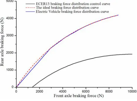
Since the vehicle is four-wheel independently driving EV, all of the four wheels have energy recovery, so the braking force distribution of the two axles should make full use the electric motor regeneration braking force, and recycling energy as much as possible, but should ensure braking security at the same time. There are three main distribution modes of composite braking force. The control parameters of the parallel control strategy is fewer, and the accuracy of control is low. The control of the best braking energy recovery control strategy is complex, and it requiring accurate control the electric motor braking force and hydraulic braking force. And the braking stability is not high. The ideal braking force distribution control strategy can make full use of the ground adhesion conditions. The braking distance is the shortest and the braking stability is the best, the capacity of braking energy recycling is very high, but the control is complicated. Therefore, considering based on the ideal
braking force distribution control strategy, the rear axle can’t locking ealier than the front axle. So the braking force distribution curve should below the ideal braking force distribution curve, but should be close to the ideal braking force distribution curve, and the curve also should meet the ECER13 regulations as premise, then it should be above the ECER13 control curve[13]. Analysis from the view point of energy recovery,the braking force is priority provided by the electric motor braking force, the inadequate part is provided by friction force. That means the braking force is priority provided by the driving axles. And because the electric motors we selected are the same four AC induction motors. When the motor rotating speed below the datum rotating speed, the motor working in constant torque mode. When the motor rotating speed above the datum rotating speed, the motor working in constant power mode. In summary, based on the idea of ensure the safety and brake energy recovery, combined with motor characteristic curve,and according to the requirements of braking strength, the braking process is divided into four stages, namely the low braking strength requirement, the moderate braking strength requirement, the medium braking strength requirement, the heavy braking strength requirement.
Figure 1. The axle’s braking force distribution
When braking strength requirement is in the low braking strength range, the axle’s braking force distribution are as follow.
L
b
k
h
G
z
F
bf g)
(
⋅
1+
⋅
⋅
=
(1)L
b
k
h
G
z
G
z
F
br g)
(
⋅
1+
⋅
⋅
−
⋅
=
(2)When braking strength requirement is in the moderate braking strength range, the axle’s braking force distribution are as follow.
G
k
b
k
h
G
k
b
k
h
G
k
k
h
a
G
k
k
h
a
L
G
k
k
h
a
L
G
k
b
k
h
G
k
b
k
h
G
k
b
k
h
G
k
k
h
a
G
k
k
h
a
G
z
F
g g g g g g g g g g bf⋅
⋅
+
⋅
−
⋅
⋅
+
⋅
⋅
⋅
⋅
−
−
⋅
⋅
⋅
−
+
⋅
⋅
⋅
−
−
⋅
⋅
+
⋅
⋅
⋅
⋅
+
⋅
−
⋅
⋅
+
⋅
⋅
⋅
⋅
−
−
⋅
⋅
⋅
−
+
⋅
=
1 1 2 2 1 1 2 2 1 1 1 1 1 1 2 2 1 1 2 2)
(
)
(
)
(
)
(
1
)
(
)
(
)
(
)
(
)
(
)
(
(3) bfbr
z
G
F
When braking strength requirement is in the medium braking strength range, the axle’s braking force distribution are as follow.
G
k
b
k
h
G
k
b
k
h
G
k
k
h
a
G
k
k
h
a
L
G
k
k
h
a
L
G
k
b
k
h
G
k
b
k
h
G
k
b
k
h
G
k
k
h
a
G
k
k
h
a
G
z
F
g g g g g g g g g g bf⋅
⋅
+
⋅
−
⋅
⋅
+
⋅
⋅
⋅
⋅
−
−
⋅
⋅
⋅
−
+
⋅
⋅
⋅
−
−
⋅
⋅
+
⋅
⋅
⋅
⋅
+
⋅
−
⋅
⋅
+
⋅
⋅
⋅
⋅
−
−
⋅
⋅
⋅
−
+
⋅
=
2 2 3 3 2 2 3 3 2 2 2 2 2 2 3 3 2 2 3 3)
(
)
(
)
(
)
(
1
)
(
)
(
)
(
)
(
)
(
)
(
(5) bfbr
z
G
F
F
=
⋅
−
(6) When braking strength requirement is in the heavy braking strength range, the axle’s braking force distribution are as follow.)
(
b
h
z
L
G
F
bf=
⋅
+
g⋅
(7))
(
a
h
z
L
G
F
br=
⋅
−
g⋅
(8)The axle’s braking force distribution is shown in Fig. 1. Where
G
represents the vehicle mass.L
represents the wheelbase.a
andb
represents the length between axles and the center of mass.h
g represents the height of centerof gravity.
z
represents the braking strength requirements.k
1,k
2,k
3 represent the braking strengthnodes.
k
1 equals to 0.4,k
2 equals to 0.55,k
3 equals to0.7.
B. Braking force distribution control
After braking force distribution of the front axle and the rear axle, the braking force requirements of four wheels is obtained, and then the four wheels braking force distribution control is carried out. By entering the wheel speed values and the battery SOC values, we calculated the electric motor braking force that the electric motor can provide under the current state . And then compared this electric motor braking force with the braking force that should be imposed on the wheel, and priority to provide braking force by electric motors, so we obtained the electric motor braking force and the hydraulic braking force that should be imposed on the four wheels. Next, the front left wheel and the rear left wheel were taken for example to explain the distribution modes.
f
F
represents the total braking force that should beimposed on the front left wheel,
F
fm_maxrepresents themaximum braking force which the motor can provide at the moment,
F
fb andF
fmrespectively represent actualhydraulic braking force and actual electric motor braking force that should be imposed on the front left wheel.
F
r,max _
rm
F
,F
rb andF
rm are represent the parameters of front left wheel, andz
represents braking strength.In OA segment
The front left wheel:
If
F
f≤
F
fm_max,then
F
fm=
F
f,F
fb=
0
. (9)If
F
f>
F
fm_max, thenmax _
fm fm
F
F
=
,F
fb=
F
f−
F
fm. (10)The rear left wheel:
If
F
r≤
F
rm_max, then
F
rm=
F
r,F
rb=
0
. (11)If
F
r>
F
rm_max,then
F
rm=
F
rm_max,F
rb=
F
r−
F
rm. (12)In AB segment
The front left wheel:
max _
fm fm
F
F
=
,F
fb=
F
f−
F
fm. (13)The rear left wheel:
If
F
r≤
F
rm_max,then
F
rm=
F
r,F
rb=
0
. (14)If
F
r>
F
rm_max,then
F
rm=
F
rm_max,F
rb=
F
r−
F
rm. (15)In BC segment
In this stage, the motor braking force decreases linearly from the maxmum to 0, while the hydraulic braking force gradually increases.
The front left wheel:
15
.
0
)
7
.
0
(
max _z
F
F
fm fm−
The rear left wheel:
15
.
0
)
7
.
0
(
max
_
z
F
F
rm=
rm−
;F
rb=
F
r−
F
rm. (17)In CD segment
The front left wheel:
)
(
b
h
z
L
G
F
g
fb
=
+
⋅
;F
fm=
0
. (18)The rear left wheel:
)
(
a
h
z
L
G
F
g
rb
=
−
⋅
;F
rm=
0
. (19)III. COMPOSITE ABS CONTROL METHOD
Composite ABS control is a control method that the electric motor ABS coordinate work with the hydraulic ABS. When braking in the low braking strength requirement, the motor works, but the hydraulic system doesn't work. When the friction coefficient was low, the
vehicle has the tendency of locking. The motor ABS judges according to wheel speed, acceleration and the slip rate to conduct anti-lock control. As the control of electric motor is sensitive and accurate than the control of hydraulic ABS system, so electric motor ABS works alone in the low braking strength requirement on low friction coefficient road. With the increasing of braking strength requirement, both of the electric motor braking and the hydraulic braking involved, at this time, the hydraulic braking force is still lower than the electric braking force, and the electric ABS is still being used to control. Continue to increase the braking strength, the stability of the electric motor is not as good as the hydraulic system, then the motor gradually stop working, and the hydraulic braking gradually take over the work. In order to ensure a smooth conversion of two ABS modes,we choose the time that the electric braking force value is fully equivalent to the hydraulic braking force value, to convert the ABS modes. In the case of braking in the heavy braking strength requirement, the hydraulic ABS works independently, to ensure the brake stability. The composite ABS control logic is shown in Fig. 2.
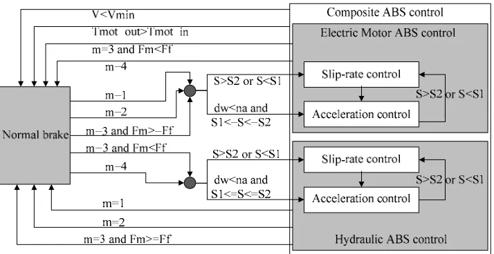
Figure 2. The composite ABS control logic
S
represents slip rate,m
represents braking modes. There are four braking strength requirements. Whenz
belongs to the range of 0 to 0.3, the braking mode is low strength requirement. When
z
belongs to the range of 0.4 to 0.55, the braking mode is moderate strength requirement. Whenz
belongs to the range of 0.55 to 0.7, the braking mode is medium strength requirement. And Whenz
is bigger than 0.7, the braking mode is heavy strength requirement. The electric motor braking force decrease to 0 whenz
belongs to the range of 0.55 to 0.7. Two modes of ABS convert in this area.The control strategies of electric motor ABS and hydraulic ABS motor are logic threshold control method[14]. The logic threshold control method is a widely used ABS control method, as its control is simple, reliable, and it have strong applications, so a double logic thresholds control logic is selected in this study. By
IV. SIMULATION MODEL
A. The process of co-simulation model
A composite ABS co-simulation model for four electric-wheel vehicles was established. AMESim and Simulink was used to establish the vehicle model and the composite ABS controller model. The software of AMESim is embedded in the Simulink model in the form
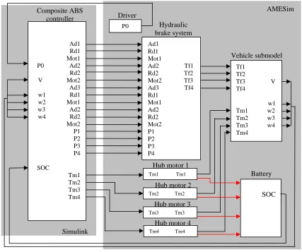
of S function to achieve the co-simulation. The flow chart of co-simulation model is shown in Fig. 3. As shown, AMESim vehicle model was mainly made up by four parts. They are the driver model, the hydraulic model, the motors and battery model, the vehicle subsystem model. And using the software of Simulink to build a composite ABS control model.
Figure 3. The Schematic of the co-simulation model
B. AMESim vehicle model
AMESim software has obviously advantages of modeling in the fields of mechanical, hydraulic, vehicle, aviation. More advanced theoretical support was used in the AMESim software, and more parameters were taken into account. The model is closer to real conditions by modeling using AMESim software , so the model is much more accurate. Therefore, the vehicle model was established by AMESim. Models used in this study is the four electric-wheel independently driving electric vehicles, vehicle model should reflect the characteristics of the studied vehicle. Reference to the 15 degrees of freedom vehicle model, which is in the application model libraries of AMESim, AMESim vehicle model was established[15]. The 15 degrees of freedom include 6 degrees of freedom of vehicle translation and rotating around the center of mass,1 degree of freedom of
steering system, and 8 degrees of freedom of four wheels moving along the vertical direction and rotating around the center of wheels’ mass[16].
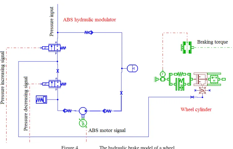
The driver model is a module to express driving commands. Through the brake pedal, resulting in the driver's demand of braking strength. Vehicle subsystem model contains steering system model, suspension model, wheel model, the road model and so on. Through the connection of AMESim module, vehicle model is easier to build. As the advantages of building a hydraulic system with AMESim is obvious, so the hydraulic model was established with AMESim. The hydraulic system we studied is a hydraulic system of four independent channels. The intention of the driver will passed to the composite ABS controller through the form of voltage signals. The hydraulic brake model of a wheel is shown in Fig. 4.
Ad1 Rd1 Mot1 P0 Ad2 Rd2 V Mot2 Ad3 w1 Rd1 w2 Mot1 w3 Ad2 w4 Rd2 Mot2 P1 P2 P3 P4
SOC
Tm1 Tm2 Tm3 Tm4
P0
Ad1 Rd1
Mot1
Ad2 Tf1 Rd2 Tf2 Mot2 Tf3 Ad3 Tf4 Rd1
Mot1 Ad2 Rd2 Mot2 P1 P2 P3 P4
SOC Tf1
Tf2
Tf3 V Tf4
w1 Tm1 w2 Tm2 w3 Tm3 w4 Tm4
Tm1 Tm1
Tm2 Tm2
Tm3 Tm3
Tm4 Tm4 Hydraulic brake system
Vehicle submodel Driver
Composite ABS controller
Battery Hub motor 1
Hub motor 2
Hub motor 3
Hub motor 4 Simulink
Figure 4. The hydraulic brake model of a wheel
AMESim electric motors model is a integration model that integrated motors, generators and converters. The model through a data file to set the limit torque data and the energy loss data. The actual torque value is the first order transfer function of the limit torque value.
lim
1
1
T
s
t
T
r
m
⋅
+
=
(20)m
T
is the torque on the axle of the electric motor.t
r isthe time constant.
T
lim is the limited torque. The battery model is a simple first order lag constant voltage source. The battery output voltage for the electric motor, and receives electric current outflow from the electric motor when regenerative braking occurs.C. Simulink / Stateflow model of the ABS controller The composite ABS controller model was built by using the software of Simulink and it’s module Stateflow[17]. The Simulink/Stateflow model is shown in Fig. 5. Simulink flowchart is mainly composed by the following components. They are the axle’s braking force distribution module, regeneration braking force calculating module, composite braking force distribution module, the slip rate calculating module, the composite ABS control module. The axle’s braking force distribution module will determine the braking intention of the driver, and calculates the braking force of the front axle, the braking force of the rear axle, and braking patterns. By calculating the input wheel speed signals and battery SOC signals, the regeneration braking force calculation module obtained the maximum regeneration braking force that each wheel can provide. The composite braking force distribution module received the axle’s braking force signals, the braking pattern signals, the braking strength signals, and the maximum regenerative braking force signals that each wheel can provide. By judging and calculating, we obtained electric motor
braking force signals and hydraulic braking force signals that should be applied to the four wheels. According to the double logic threshold control method, the composite ABS control module analyzed the wheel acceleration signals and the slip rate signals, and enforced pressure increasing, pressure decreasing, and pressure keeping and other commands. Because the Stateflow is a module of Simulink, and it can exchange data and signals with other modules. By function call it can trigger the implementation of Simulink blocks actions. So the core of composite ABS control model was built with Stateflow module. Stateflow module received the continuous changed signals of vehicle speed, wheel speed, wheel acceleration and slip rate and so on, produced pressure insreasing, pressure decreasing, pressure keeping and so other commands, made the slip rate in the vicinity of the best slip rate, and it improved the vehicle lateral stability. Through the S-function embedded in Simulink, the Simulink model of the composite ABS controller exchange data and signals with AMESim, to make the two models joint work.
V. SIMULATION ANALYSIS
A. Simulation parameters settings
Braking process on low-adhesion wet road is simulated. First, we set the parameters. Specific parameters are shown as below.
TABLE I.
PARAMETERS FOR CO-SIMULATION
Parameters Value Unit
Sprung mass 1300 kg
Wheelbase 2400 mm
B. Simulation results
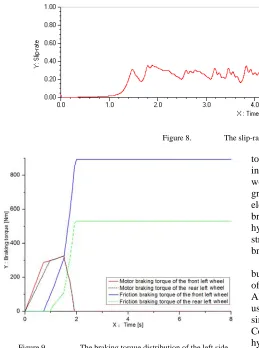
The adhesion coefficient of the road is 0.4. The braking strength requirement increases from 0 to the target braking strength requirement within 2 second,and then keep unchanged. That means the braking condition is braking on wet cement road. The initial speed of vehicle is 100 km/h. Through simulation, the wheel speed map, the braking torque map, the slip-rate map were obtained, which are shown in Fig. 6, Fig. 7 and Fig. 8.
From Fig. 6, it can be seen that the curve of the wheel speed below the curve of the vehicle speed. The wheel speed have some fluctuations. In Fig. 7, the red curve represents the electric motor braking torque, and black curve represents the hydraulic friction braking torque. By comparing the data, it can be seen that two kinds of braking modes handover at the time of 1.7s. In the
vicinity of 1.7s, the distributed electric motor braking force equals to the distributed friction braking force. The electric motor ABS was working before 1.7s, after that time, the electric motor ABS stop working, but friction braking ABS start working. In Fig. 8, the curve of slip rate fluctuat around the range of 0.2 to 0.3 most of the time, so the slip rate control is good. Also, the braking torque distribution of the left side wheels is shown in Fig. 9. Through contrast to some research results, the simulation results indicate that the composite ABS control method can effectively control the vehicle model. The slip-rate is controlled in the ideal range, and wheels are not locked. So, it proved that the composite ABS system is able to improve the braking stability, and keep the vehicle safety.
Figure 5. The Simulink/Stateflow model of ABS controller
Figure 6. The rear left wheel speed and the vehicle speed
Figure 8. The slip-rate of the rear left wheel
Figure 9. The braking torque distribution of the left side wheels
VI. CONCLUSION
A composite ABS control method based on four electric-wheel independently driving EV is presented. As all of the four electric wheels can recover energy, by analyzing the ideal braking force distribution and the ECE braking curves and regulations, we proposed a composite braking force control distribution method that the electric motor braking combined with hydraulic braking. The braking force distribution method considered not only the energy recovery but also the braking stability. Meanwhile, according to the rules of composite braking force distribution, proposed a composite ABS control method that motor ABS control coordinate with hydraulic ABS control. When the driver’s demand of braking strength is relatively low, electric motor brake is able to meet braking requirement, so we use pure electric motor braking and pure electric motor ABS control. When the braking strength requirement is in the moderate range, electric motor brake may not fully meet the braking requirements, then hydraulic brake start to work. In this range, hydraulic braking is the supplement of the electrical motor braking, so anti-lock control is still provided by electric motors. When the demand of braking strength increases again, that is in the medium braking strength range, the hydraulic braking force is very stable in the medium braking strength range, and the electric motor braking
torque which provided in this range is limited. Therefore, in this range, the electrical braking force gradually stop working. In the range, when the electric braking force is greater than the hydraulic friction braking force, the electric motor ABS control works, when the electric braking force is less than the friction braking force, the hydraulic friction ABS control works. When the braking strength requirement is in the heavy range, the hydraulic braking and hydraulic ABS woks independently.
According to this method, a co-simulation model was built based on AMESim and Simulink. The vehicle model of 15 degrees of freedom is built by using the software of AMESim, while the composite ABS controller is built by using the software of Simulink. Co-simulation model simulated the EV braking on low friction coefficient road. Coordination work of the electric motor ABS and the hydraulic ABS can be seen from the simulation figures. Simulation results shown that the composite ABS controller can guarantee the slip rate within reasonable limits, and can improve the vehicle lateral stability, so that the traffic safety is improved.
REFERENCES
[1] S. Z. Ming, and H. Tian, “A dynamics simulation on an electric vehicle with electric-wheel drive,” Automotive Engineering, China, vol. 29, no. 2, 2007.
[2] N. Mutoh and H. Yahagi, “Control methods suitable for electric vehicles with independently driven front and rear wheel Structures,” IEEE Vehicle Power and Propulsion, Chicago, pp. 2005: 638-645, Sept 2005.
[3] Y. Hori, “Future vehicle driven by electricity and control-research on four-wheel-motored,” IEEE Trans. on Industrial Electronics, USA, vol. 51(5), pp. 954-962, 2004.
[4] Y. M. Gao, “Electronic braking system of EV and HEV
integration of regenerative braking,” Automatic Braking Force Control and ABS. SAE paper 2001-01-2478, 2001. [5] F. Sangtarash, V. Esfahanian, H. Nehzati, S. Haddadi, M.
A. Bavanpour B. Haghpanah, “Effect of different regenerative braking strategies on braking performance and fuel economy in a hybrid electric bus employing CRUISE vehicle simulation,” SAE paper 2008-01-1561, 2008. [6] P. Y. Wang, Q. N. Wang, A. P. Hu, Y. B. Yu, “Analysis of
regenerative brake system of hybrid bus based on
Simulink-AMESim co-simulation,” Journal of Jilin
University (Engineering and Technology Edition), vol. 38 Sup. pp.7-11, Feb 2008.
Intention,” Automotive Engineering, vol. 31, no. 3, pp.244-249, 2009.
[8] E. Nakamura, M. Soga, A. Sakai and et al, “Development of Electronically Controlled Brake System for Hybrid Vehicle,” Toyota Motor Corporation, SAE, 2002(01):0300, 2002.
[9] Z. P. Yu, Y. C. Zhang, L. Xu, L. J. Zhang and L. Xiong, “Study on Brake Force Distribution Methods of Hybrid Brake System,” Automobile Techonology, vol. 5, pp.1-4, 2008.
[10]Y. Zhou, S. J. Li, H. B. Tian, Z. D. Fang, Q. X. Zhou, “A control strategy for ABS system of four-wheel motor drive EV,” Automotive Engineering, vol. 29, no. 12, 2007. [11]Q. Z. Chen and R. He, “Motor and hydraulic braking force
distribution in car regenerative braking system” Journal of Jiangsu University(Nature Science Edition), vol. 29, no.5, 2008.
[12]R. He and Q. Z. Chen, “Vehicle regenerative braking using dual switched reluctance motors/generators,” Journal of Jilin University (Engineering and Technology Edition), vol. 39, no. 5, 2009.
[13]G. Z. Zhao, Z. L. Yang, M. X. Wei, S. Pan, W. G. Meng, “ECE regulation based modeling and simulation of control strategy for regenerative braking in EV and HEV,” Journal of Wuhan University of Technology (Transportation Science & Engineering), vol. 32, no. 1, Feb 2008.
[14]Y. L. Fang, Theory and Design of Automotive Brake,
Beijing: National Defense Industry Press, 2005.
[15]Y. L. Fu and X. Y. Qi, AMESim system modeling and
simulation- from entry to the master, Beijing: Beijing University of Aeronautics and Astronautics Press, 2006. [16]A. P. Hu, “The research of regenerative braking system
based on AMESim-Simulink co-simulation,” Changchun: Dissertation for the degree of Master at Jilin University, 2008.
[17]J. Sun, Z. K. Zhu, A. D. Yin, Z. M. Yang, “Research on the hybrid modeling and simulation of the anti-lock braking system,” Journal of system simulation, 2004(9), pp. 2059-2062, 2004.
Chuanxue Song, male, born in 1959. Ph.D. Vice-President and PhD supervisor of College of Automotive Engineering, Jilin University, China. Professor of State Key Laboratory of Automobile Dynamic Simulation
Ji Wang, male, born in 1981. Ph.D student. Ph.D student of State Key Laboratory of Automobile Dynamic Simulation, College of Automotive Engineering, Jilin University, China.