UNIVERSITY OF OKLAHOMA GRADUATE COLLEGE
DESIGN, IMPLEMENTATION, AND EVALUATION OF JOIN AND SPLIT STRATEGY FOR TRANSMISSION CONTROL PROTOCOL RUNNING ON
SOFTWARE DEFINED NETWORKS
A DISSERTATION
SUBMITTED TO THE GRADUATE FACULTY in partial fulfillment of the requirements for the
Degree of DOCTOR OF PHILOSOPHY By WEI GUO Norman, Oklahoma 2017
DESIGN, IMPLEMENTATION, AND EVALUATION OF JOIN AND SPLIT STRATEGY FOR TRANSMISSION CONTROL PROTOCOL RUNNING ON
SOFTWARE DEFINED NETWORKS
A DISSERTATION APPROVED FOR THE SCHOOL OF COMPUTER SCIENCE
BY
Dr. Sridhar Radhakrishnan, Chair
Dr. S. Lakshmivarahan
Dr. Qi Cheng
Dr. Mohammed Atiquzzaman
© Copyright by WEI GUO 2017 All Rights Reserved.
Acknowledgements
This dissertation could not have been finished without the help and support from a number of individuals. I would like to express my deepest appreciation to all of them. First of all, I am deeply grateful to my advisor and committee chair Dr. Sridhar Radhakrishnan. He guided me through this wonderful journey and provided valuable feedback throughout my doctoral work.
Furthermore, I would like to thank Dr. Mahendran Veeramani for his understand-ing, patience and valuable feedback. My thanks also go out to Dr. Yuh-Rong Chen who spent countless hours helping me develop the Integer Programming models.
I further like to thank the professors with whom I had taken classes, which had laid a solid foundation for my research work.
My special gratitude goes to my friends and colleagues: Yiming Xu, Michael Nelson, and Jincheng Zhuang for stimulating discussions and their readiness to help. My special thanks are extended to the wonderful staff members in the School of Computer Science at the University of Oklahoma, Jonathan Mullen, Virginie Perez Woods, Lindsay Rice, and James Cassidy for their timely help, encouragement, and advice since my first day in this program.
Last but not least, I would like to thank all my family members for their love, encouragement and support. Especially my parents, Chengfa Guo, Chenguang Huang who raised me and supported me in all my pursuits; and my wife Xuan Qi who is always gave me her best wishes and support; and my daughter Jade X.Guo who always cheers me up.
Table of Contents
Acknowledgements iv
List of Tables vii
List of Figures x
Abstract xi
1 Introduction 1
1.1 Software Defined Network SDN . . . 2
1.2 Transmission control protocol (TCP) . . . 6
1.2.1 TCP Connection Establishment and Termination . . . 6
1.2.2 TCP Fairness . . . 9
1.2.3 TCP Proxy . . . 10
1.3 Smart Grid . . . 12
1.4 Gaming traffic . . . 13
1.5 Virtual machine live migration . . . 16
1.6 Contributions of this dissertation . . . 18
2 Join and spilt TCP for SDN network: design, implementation and evaluation 20 2.1 Introduction . . . 20
2.2 System Design and Implementation . . . 23
2.3 SDN-based TCP Join and Split Framework . . . 24
2.3.1 SDN-based TCP join and split . . . 26
2.3.2 Preserving End-to-End Flow Semantics with ’Linked-ACK’ . . 28
2.3.3 Linked-ACK Framework Based TCP State Machine . . . 30
2.4 Performance Evaluation and Results . . . 33
2.4.1 Aggregated TCP Goodput Performance . . . 33
2.4.2 Linked-ACK Throughput Performance . . . 35
2.4.3 Proxy Buffer Analysis . . . 35
2.4.4 Fairness Application . . . 37
2.4.5 Wireless Application . . . 37
2.4.6 MPTCP Application . . . 41
2.5 Summary . . . 44
3 Achieving Throughput Fairness in Smart Grid Using SDN-Based Flow Aggregation and Scheduling 45 3.1 Introduction . . . 45
3.2 Smart Grid Network Model . . . 48
3.3 Proposed SDN-Based Aggregator/Scheduler Framework . . . 51
3.4 Performance Evaluation . . . 56
3.5 Summary . . . 64
4 Improved Video Throughput and Reduced Gaming Delay in WLAN Through Seamless SDN-Based Traffic Steering 65 4.1 Introduction . . . 65
4.2 System Model . . . 68
4.3 Proposed SDN Fairness Model . . . 69
4.3.1 Network Flow in the Proposed Framework . . . 71
4.4 Delay and Throughput Analysis of the Proposed Framework . . . 73
4.5 Performance Evaluation Study . . . 74
4.6 Summary . . . 82
5 On Scheduling Multiple Simultaneous Live Virtual Machine Migra-tions 83 5.1 Introduction . . . 83 5.2 Problem Formulation . . . 86 5.2.1 Simplified Formulation . . . 90 5.2.2 Examples . . . 91 5.3 Complexity . . . 94 5.4 Greedy Algorithms . . . 95
5.4.1 Greedy Algorithms for Model VMLM and VMLM-Simplified . 95 5.4.2 Implementation . . . 98
5.5 Performance Evaluation and Result Analysis . . . 99
5.6 Summary . . . 104
6 Conclusions and Future Work 105 6.1 Conclusions . . . 105
6.2 Future Work . . . 107
List of Tables
2.1 Aggregated TCP throughput and confidential interval . . . 34
4.1 Average TCP throughput of each clients (in kbps) for the proposed and traditional experiment setup. . . 75
4.2 Average UDP throughput (in kbps) for two clients setup, for the pro-posed and traditional experiment setup. . . 78
5.1 bandwidth allocation and Scheduling for Case 1 . . . 94
5.2 bandwidth allocation and Scheduling for Case 2 . . . 94
5.3 bandwidth allocation and Scheduling for Case 3 . . . 94
5.4 bandwidth allocation and Scheduling for Case 4 . . . 94
5.5 bandwidth allocation and Scheduling for Case 2 . . . 103
List of Figures
1.1 SDN Architecture . . . 4 1.2 OpenFlow protocol . . . 4 1.3 SDN Testbed . . . 5 1.4 TCP Connection Establishment . . . 7 1.5 TCP Connection Termination . . . 8 1.6 TCP state Diagram . . . 9 1.7 TCP proxy on SDN platform . . . 111.8 Client-server network model . . . 14
1.9 VM Live Migration Pre-copy and Stop-and-copy phase . . . 17
2.1 System Model. Clients, switches and proxies are wired connected. SDN controller connects to both switches and is expanded to connect to both switches . . . 23
2.2 SDN join and split control plane. When a new SYN segments come to switch, the SDN control plane execute the program following the step 1 to 6 . . . 25
2.3 SDN join and split data flow initiation using TCP SYN segments . . 26
2.4 Linked-ACK. It shows the ACK collection, caching and distribution with relative installed flow tables . . . 28
2.5 TCP state diagram. This diagram show hows how Linked-ACK couples the proxy sender and receiver TCP state . . . 32
2.6 Goodput comparison of aggregated TCP flows vs equivalent regular TCP flows . . . 34
2.7 Linked-ACK throughput of the client to the join-proxy (show as client) the split-proxy to the server (show as server). These two flows synchro-nized by Linked-ACK. . . 35
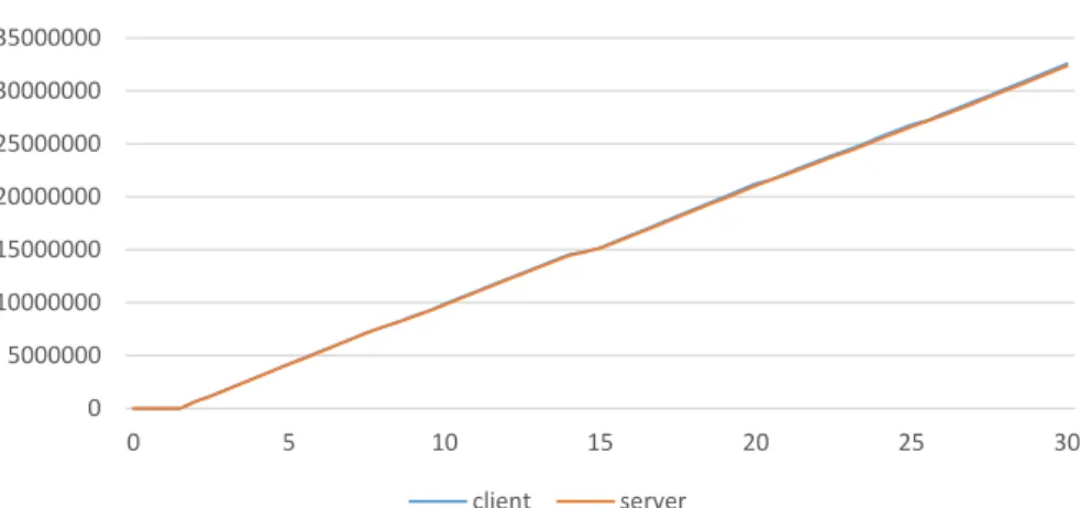
2.8 Linked-ACK Total received byte of the client to the join-proxy (show as client ) the split-proxy to the server (show as server). Two lines are almost overlapped . . . 36
2.9 Linked-ACK client congestion window size and two proxies queue size. The queue size of each proxy is always smaller than the congestion window size . . . 36
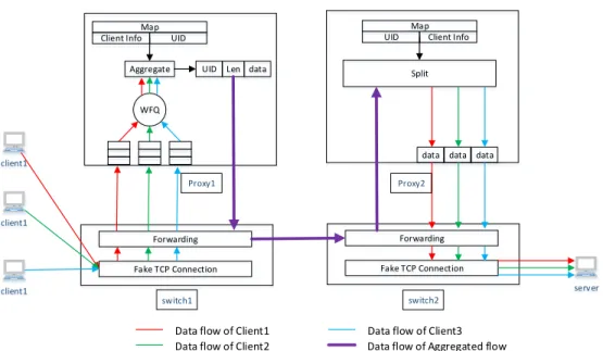
2.10 Schematic diagram showing the flow of data segments between clients and server in our Proposed network framework with flow aggregation using Weighted Fair Queue (WFQ) . . . 38
2.11 Schematic diagram showing the flow of ACK segments between clients and server in our Proposed network framework with flow aggregation using Weighted Fair Queue (WFQ) . . . 38
2.12 Three TCP flows unfair throughput. TCP receive throughput of three TCP flows with TCP CUBIC congestion control algorithm. . . 39 2.13 Three TCP flows fair throughput. TCP receive throughput three TCP
flows with weighted round robin application on proxy . . . 39 2.14 Three TCP flows fair throughput. TCP receive throughput three TCP
flows with weighted round robin application on proxy . . . 39 2.15 TCP throughput performance in a wireless network environment . . . 42 2.16 TCP delay performance in wireless network environment . . . 42 2.17 Multipath TCP throughput with proxy. Two subflows of MPTCP
successfully convert to conventional TCP. The Linked-ACK preserved the end-to-end semantics and synchronized well with MPTCP subflows 44 3.1 Schematic diagram of OpenFlow network with Aggregator-cum-Scheduling (AS)
nodes. For brevity, SDN controller is not shown. Also the smart-meters in suburb, and citycenter regions are not shown. . . . 50 3.2 Internal functionality of the proposed framework with single
aggrega-tor/scheduler node. For brevity, only the connection-sequence related to eNB-1 is shown. . . . 51 3.3 Weighted round robin scheduling and aggregation implementation at
the AS node . . . 53 3.4 Markov Chain Model Long TCP Congestion Window Size Evolution in
CA phase. Where p(i) is the loss probability with congestion window size of ‘i’ packets. . . 54 3.5 eNBs TCP throughput with aggregation and without scheduling. . . . 57 3.6 eNB TCP throughput in Proposed Aggregation and Scheduling
Frame-work. Thehorizontal lines and the respective values show the analytical average throughput, as computed from Eq. 3.4. . . 58 3.7 Throughput fairness index of 3 different frameworks, computed using
Eq. 4.6. . . 60 3.8 Individual UEs throughput in without aggregation and scheduling. . 61 3.9 Individual UEs throughput in with proposed aggregation and
schedul-ing. The horizontal line shows the analytical throughput average value. 62 3.10 Throughput probability distribution for three policies, no aggregation,
aggregation without policy, and proposed aggregation with policy . . 63 4.1 WLAN System Network Model. Solid line indicates wired connection,
and dotted lines indicate WiFi wireless connection. . . 69 4.2 Proposed SDN based WLAN Network Architecture. . . 72 4.3 Real testbed used for the performance study. . . 75 4.4 Gaming traffic Ping delay (in ms) for the respective proposed and
traditional setup. X-axis represents the total number of gaming clients. 76 4.5 Video traffic delay (in ms) for TCP-only analysis and experiment, and
TCP+UDP experiment results. X-axis represents the total number of gaming clients. . . 77
4.6 TCP Throughput Fairness comparison among traditional and proposed
frameworks, for 3 Clients set up. . . 79
4.7 TCP Throughput Fairness comparison among proposed and traditional frameworks, for 4 Clients set up. . . 80
4.8 UDP Throughput Fairness comparison among proposed and traditional frameworks, for 1 game server and 2 game clients set up. . . 81
5.1 Fat-Tree Topology . . . 92
5.2 end-user agnostic TCP join and split framework in SDN . . . 99
5.3 Average total performance degradation of Model VMLM . . . 101
5.4 Average makespan of Model VMLM . . . 101
5.5 Average total performance degradation of Model VMLM-Simplified . 102 5.6 Average makespan of Model VMLM-Simplified . . . 102
Abstract
Software Defined Networks (SDN)-enabled switches of today can be empowered to intelligently forward as well as elastically steer the network traffic. In this work, we fo-cus on developing a SDN-based framework to provide improved delivery performance (of applications) in the network.
This dissertation proposed a new TCP join and split proxy on SDN platform. The proposed framework allowed part of TCP (Transmission Control Protocol) optimiza-tion to migrate from the applicaoptimiza-tion server to the proxy. Therefore, with a control plane built between SDN controller and proxy, the SDN controller can further improve the TCP delivery performance. The proxy (join-proxy) joins all TCP flows at the beginning of the shared path into one long TCP flow. At the end of the shared path, the proxy (split-proxy) splits the long flow for each joined client with the same TCP session state. With the help of centralized controller of SDN and customized SDN switch, the new design simplifies the TCP session synchronization between proxies. Also, this dissertation developed Linked-ACK ((Acknowledgement) to maintain the end-to-end semantic and limit the buffer size in each proxy by coupling the ACK of three TCP flows separated by the join and split proxy. At the last, this dissertation shows that the proposed proxy can well integrate with wireless network and MPTCP (Multi-Path TCP) proxy [1]
The extensions of the proposed TCP Join and Split platform are applied to Smart Grid network for improving fairness, WiFi network for reducing gaming traffic de-lay, and Data Center network for addressing Virtual Machine (VM) live migration problem.
network to provide better fairness on the application layer. The latest research in Smart Grid communications has advocated the aggregation of multiple traffic flows in order to achieve an improved throughput. While aggregation improves the overall throughput, the individual flows still suffer from unfair throughput performance. As a result, the enablers for time sensitive Smart Grid services, such as load-shedding which requires a timely report of data, are mostly affected.
This dissertation proposed a novel SDN-based framework to provide fairness among smart-meters (SMs) through flow aggregation and scheduling. By exploring the SDN’s flow-level manageability features, for the first time in this paper, we present an implementation-based architecture to perform effective aggregation-and-scheduling of traffic flows. The proposed framework ensures fairness (among the smart-meters) as well as improve the throughput performance. Our extensive experimental results validate the efficacy of our proposed framework.
Second, the proposed TCP Join and Split platform can be applied to WiFi network to reduce the gaming traffic delay. WiFi users typically expect different performance requirements for various types of applications. For instance, users expect 'better and consistent throughput' for Internet video consumption, and 'minimal delay' for local network gaming applications. The wireless access substrate (at the consumer-end), typically being the bottleneck in these networks, causes different users (in the same WiFi coverage) to experience unfair and fluctuating network performance. To com-bat such unfair situations, we need approaches to effectively control and steer the applications’ traffic in the shared WiFi medium. However, a network that deals with a crowd or private end-users (such as gaming multiplayers or the Internet content dis-tributors), encounters a major challenge in controlling the traffic without involvement or modification at the end-host application devices.
In this dissertation, we propose a SDN-based seamless traffic steering and control strategy in order to provide effective application-specific delivery services, such as
reduced delay (for gaming traffic) and improved throughput (for video consumption). Unlike simulation-based solutions, our approach is production-ready, as we have im-plemented our framework on a real network testbed environment. With extensive performance study and sufficient mathematical insight, we demonstrate the prowess of our proposed framework.
Last but not the least, the proposed TCP Join and Split platform can be applied to Data Center network to optimize the VM live migration. With the growth of data volumes and a variety of Internet applications, virtualization has become common-place in modern data centers and an effective solution to provide better management flexibility, lower cost, scalability, better resources utilization, and energy efficiency. One of the powerful features provided by virtualization is Virtual Machine (VM) live migration, which facilitates moving workloads within the infrastructure with negligi-ble downtime and minimal impact on workload. However, the performance of running applications is likely to be negatively affected during a live VM migration. The objec-tive of this paper is to optimize the total performance degradation of concurrent VM live migration in the data center network by exploiting the SDN platform. The prob-lem is modeled using mixed integer linear programming(MILP) for VM live migration with a fixed path and VM live migration with path selection. To provide a practical optimization, the greedy algorithm is proposed. Numerical study results show that a significant decrease occur in performance degradation in MILP model and greedy algorithm when the number of VMs increases. The proposed greedy algorithm can-not yield the optimum solution as the problem become harder, but it provides better solution than MILP model in terms of the time constrain exhibited in case of large problems.
Chapter 1
Introduction
There has been an enormous growth in the number of connected devices to the Inter-net which in turn has produced high-speed and high-capacity Inter-networks and routers that are capable of processing packets at rapid speed. For example, Juniper T-series routers can forward in up wards of 30 billion packets per second. Such extreme speeds are only possible with high-speed and multi-core router architectures. With at advent of such high-speed router architectures is it natural to determine if the routers can provide additional computational help other than providing the packet header lookup and forwarding service. In fact, many router manufacturers have provided additional services to run on the routers such as deep packet inspection to detect worms and viruses based on known signatures.
The route control protocols and configuration of the routing tables are accom-plished by routers using its control plane. The data plane is responsible for determin-ing which output port to send the packet based on the destination address. Routers also provide services such as monitoring and configuration services and this consti-tutes the management plane. Software Defined Network (SDN) consists of routers that run the SDN software which enhances the ability of the data, control, and man-agement planes. With the availability of SDN routers, it becomes easy to control the network traffic that is based on user-defined rules and not the one size fits all approach of the current routers. As packets enter the SDN enabled router, the rules are applied, which may require deep packet inspection and the packet is forwarded to the user defined output port on the router.
1.1
Software Defined Network SDN
SDN is a new network architecture that decouples the control and data planes and allows the network control to be directly programmable [2]. Compared to, the network gains programmability, automation, and network control to build highly scalable, flexible, and adaptable networks.
A high-level view of SDN architecture is shown in Figure 1.1. The goal of SDN architecture is to provide a controlled connection and open interface for enabling the developer to inspect and modify the network traffic. SDN architecture can be divided into data plane, control plane, and application plane. The data plane contains the network elements implemented with SDN datapath which consists of Control-Data-Plane Interface (CDPI) agent to communicate with control plane, and forwarding engine and processing function which process packets following the management of CDPI. Both physical and virtual switches can be network elements. The application plane implements the business logic to the network through the Northbound Interfaces (NBIs) provide by the control plane which allows the control plane to communicate with a higher-level component that is application plane in the SDN architectures. Therefore, the control plane working between data plane and application plane trans-lates the business logic to the low-level interface in the SDN datapath and information up to the application.
Control to Data-Plane Interface (CDPI) is an open source, vendor-neutral, and an interoperable interface between the control plane and data plane. The essential components of this interface are the flow table and external controller. When a first packet belonging to a flow (a flow is a sequence of packets going from a source to a destination) enters a SDN router for the first time, the packet is sent to a controller - an external device that is connected to the same network. The controller then inserts forwarding information including packet matching rules on all the routers in
the path from source to destination. The place when you insert this information is called the Flow-Table. The Flow-Table contains packet matching rules and actions that correspond to them. For example, an action would be discard the packet (as for example when a virus is detected).
One of the most well known CDPI is OpenFlow that provides an open proto-col to program the flow table in different switches and routers [3]. The OpenFlow Switch and Controller communicate via a secure channel, which defines three message types, controller-to-switch, asynchronous, and symmetric. The controller initiates Controller-to-switch messages to manage and inspect the state of the switch, such as insert or remove flow tables. The switch initiates asynchronous messages to update the controller of network state of the switch, such as new packets come in, links lost connection. Symmetric messages are initiated by either the switch or the controller and mainly used for maintaining the connection between the switch and controller [4]. A packet received by OpenFlow switch is matched on each of the flow tables on each router shown as Figure 1.2. Each Flow-Table contains multiple flow entries. A flow entry in the OpenFlow Flow-Table consists of six fields: (1) Match Fields: match against packets (2) Priority: provide precedence for each flow entry (3) Counters: calculate matched packets (4) Instructions: modify the action set (5) Timeouts: is the expired time (6) Cookie: is used for the controller to analyze flow entries [4].
In the market, OpenFlow protocol is supported both on commercial and virtual switches. Mininet [5] is one of the most successful OpenFlow network simulator enabling to build an OpenFlow network on the local machine. Moreover, there are several controllers that implemented OpenFlow protocol, such as Floodlight [6] and Nox [7]. In this report, we use Floodlight as the controller to show an example of simulated OpenFlow testbed. Shown in Figure 1.3, the OpenFlow network is comprised of 4 OpenFlow (OF) switches which are simulated in Mininet simulation environment. The Controller Floodlight is logically linked to all the OFSwitches.
Network Element
SDN Application SDN Application SDN Application
A p p li ca ti o n P la n e C o n tr o l P la n e Da ta P la n e SDN App Logic NBI Driver SDN App Logic NBI Driver SDN App Logic NBI Driver SDN Controller NBI Agent SDN Control Logic CDPI Driver SDN Datapath CDPI Agent Forwarding Engine Processing Function Network Element SDN Datapath CDPI Agent Forwarding Engine Processing Function Figure 1.1: SDN Architecture Controller OpenFLow Channel Flow Table 1 Flow Table 2 Flow Table n OpenFlow Protocol
Local or Remote
Mininet
OFSwitch 1 OFSwitch 2 OFSwitch 3 OFSwitch 4 Controller : Floodlight Figure 1.3: SDN Testbed1.2
Transmission control protocol (TCP)
TCP has been proposed since 1981 [8] and is still one of the most popular protocols in the current internet. TCP is a reliable end-to-end, connection-oriented, byte-stream protocol of transport layer of OSI model [9]. TCP flows start with establishing a connection between two hosts to initialize and maintain the session for the data stream. Data can be delivered in-order of a stream of bytes in each direction on top of a less reliable network. TCP also includes flow control mechanism which re-transfers lost packets and adopt sending data speed according to the network status. Moreover, the TCP provides security mechanism and allows many simultaneous TCP flows within a single host.
1.2.1 TCP Connection Establishment and Termination
In the normal case, TCP uses a Three-Way Handshake to establish a connection shown as Figure 1.4. The purpose of Three-Way Handshake is that the Client and Server agree on the starting sequence numbers that the two sides want to use for their respective byte streams [10]. The following the process of Three-Way Handshake:
1. Both client and server start from CLOSE state. The Client performs an active open which creates a transmission control block (TCB) to store all the important information about the connection and sends out a SYN message to the server with a random sequence numberX. Then the Client moves to SYN-SENT state to wait for an acknowledgment (ACK) to SYN. The Server creates a TCB and moves to LISTEN states to wait for contact from a client.
2. The server receives the SYN message and replies with am SYN-ACK message which the acknowledgment number is the received sequence number X plus 1, and the sequence number is random number Y generated on the Server. Then
the Server moves to SYN-RECEIVED state to wait for the ACK message. 3. Finally, the Clint receives the SYN+ACK that confirms the sequence number X
is received on the Server. Then the client sends back an ACK which the sequence number is received X + 1, and acknowledgment number is Y + 1. Then the Client moves to ESTABLISHED state. The Server receives the ACK and also moves to the ESTABLISHED state. Since then, a full-duplex communication is established. Client Server Client State CLOSED SYN-SENT ESTABLISHED Server State CLOSED LISTEN SYN-RECEIVED ESTABLISHED
Wait for Server Active Open: Create TCB, Send SYN
Wait for ACK to SYN
Receive SYN+ACK, Send ACK
Passive Open: Create TCB
Wait for Client Receive SYN, Send SYN+ ACK
Wait for ACK to SYN
Receive ACK SYN SYN+ACK ACK #1 #2 #3
Figure 1.4: TCP Connection Establishment
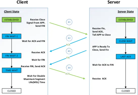
In the typical case, the TCP uses Four-Way Handshake to close the connection [11] shown as Figure 1.5. Each side of the connection terminates the connection independently [12]. The process of Four-Way Handshake is similar to TCP Three-Way Handshake. When the Client wishes to terminate the connection, it sends a FIN message to the server and moves to FIN-WAIT-1 state to wait for ACK and FIN from the server. The server receives FIN, sends ACK, informs the application (APP) to stop, and moves to CLOSE-WAIT state. When the APP on Server is ready to close, the Server sends FIN to the Client and move to LAST-ACK state. Once the
Server receives the ACK to FIN, it closes the connection move to CLOSE state. The Client side is more complicated than the Server. The Client receives the ACK and moves to FIN-WAIT-2. Then the Client receives FIN, sends ACK to the server, and moves to TIME-WAIT. After 2 Maximum Segment Life(MSL), the Client closes the connection and moves to CLOSE state.
The TIME-WAIT state is designed for two purposes: First, it makes sure the ACK reliable transmit to the Server. Second, it provides a time gap to isolate the current connection with any subsequent ones. Otherwise, the TCP segments from different connections could be confusion. Hence, the Client in TIME-WAIT state is not available for establishing a new connection. The standard MSL is 120s. In modern networks, the operating system allows selecting a lower value if it will lead to a better performance. Client Server Client State CLOSED FIN-WAIT-1 ESTABLISHED Server State CLOSED CLOSE-WAIT LAST-ACK ESTABLISHED Receive Close Signal From APP, Send FIN
Wait for ACK and FIN
Wait for FIN Receive FIN, Send ACK
Receive Fin, Send ACK, Tell APP to Close
APP is Ready To Close, Send Fin
Wait for ACK to FIN
Receive ACK FIN ACK ACK #1 #2 #4 FIN-WAIT-2 TIME-WAIT Receive ACK
Wait For Double Maximum Segment Life(MSL) Time
FIN #3
Figure 1.5: TCP Connection Termination
The TCP state diagram shown as Figure 1.6 is a summary of the TCP state transi-tion for both TCP connectransi-tion establish and terminate. In additransi-tional, it demonstrates
the edge cases for simultaneously establishing and terminating TCP session. More details can be found in [8]
CLOSED LISTEN ESTABLISHED SYN_RCVD SYN_SENT FIN_WAIT_1 FIN_WAIT_2 CLOSING TIME_WAIT CLOSED CLOSE_WAIT LAST_ACK
Passive open Close
Close Active open/SYN SYN/SYN+ACK SYN/SYN+ACK Send/SYN ACK SYN+ACK/ACK Close/FIN Close/FIN ACK FIN/ACK FIN/ACK ACK FIN/ACK ACK Close/FIN
Timeout after two maximum segment
lifetimes
Figure 1.6: TCP state Diagram
1.2.2 TCP Fairness
The flow control mechanism also provides TCP fairness. If K TCP sessions share same bottleneck link of bandwidth R, each should have an average rate of R/K. This dissertation uses Jain’s fairness index [13] to measure the TCP fairness. The equation is shown in Eq 2.1 where xi represents the throughput of TCP flow-i, n is the total number of flows. If each TCP flow shares the bottleneck link equally, then F = 1 is the upper bound of Jain’s fairness index and stands for the best fairness. The worst case is that one flow occupies the entire bandwidth of the bottleneck, then F = 1
the lower bound of Jain’s fairness index and stands for the worst fairness. F(x1, x2..., xn) = (Pn i=ixi)2 nPn i=ix2i (1.1) 1.2.3 TCP Proxy
A TCP proxy [14] consisting of multiple TCP servers and clients acts as an interme-diary node between clients and remote servers. For each TCP flow from the client to the remote server, a TCP proxy maintains two TCP sessions which are from the client to TCP proxy server and TCP proxy client to the remote server. The TCP proxy server receives the layer 5-7 data from the client and forwards it to the remote server from the TCP proxy client. TCP proxy also can perform more than forwarding data, such as provides weighted fair queue that allows TCP proxy to define traffic classes and then assign different bandwidth to each class [15], initials TCP session with optimized TCP configuration other than the default of the client and remote server [16].
However, lacking the globe view of the network, the proxy doesn’t have the capac-ity to make a global optimum decision. Extending the SDN controller to fully control the TCP proxy will solving this problem, shown as Figure 1.7. SDN controller not only keeps tracking the entire network but also can monitor and manipulate the pack-ets of layer 2-4. TCP proxy is further expanded, such as can be transparent to both client and the remote server, cooperate with other TCP proxies, glue each TCP flow control status together.
This dissertation optimize the performance of TCP with SDN in different network scenario by exploiting TCP proxy. A few recent studies have focused on improving the TCP throughput performance through the technique of combining different flows in the network. In [17], the authors with the help of simulation experiments improve the smart grid meters’ traffic through a flow-aggregation framework. Along similar lines,
Controller
client2
client1
client3
TCP proxy
SDN Control PlaneRemote server
TCP flow of client1 TCP flow of client2 TCP flow of client3Figure 1.7: TCP proxy on SDN platform
in a LTE-based wireless smart grid scenario [18], we showed that with appropriate TCP aggregation and scheduling, fairness among the TCP flows can be achieved (in addition to obtaining improved throughput).
In a different work [19], we proposed an integration of IoT-based MQTT mes-sages at the edge switches (also known as fog nodes) for achieving improved deliv-ery performance. The aforementioned works in common support the logic of simple flow-aggregation frameworks that cannot be non-trivially extended and applied to generic network scenarios that involve flow joining and splitting of flows. In a dif-ferent work [20], we proposed split-only framework to separate flows into a chain of two flows with first flow providing congestion-free wireless transport, and the second (part of the) wired-network flow providing regular congestion based TCP transport.
Unlike the existing works that independently address either aggregation-only [18] or split-only [20] frameworks of TCP flows, in this dissertation, we propose a unified
join-and-split framework of TCP flows that provides an effective information synchro-nization platform among the join and fork proxy points in the network. This feature enables aggregation and split functionality to work at different points of the same network.
Works such as [21] [22] [23] exploit the idea of preserving end-to-end semantics of flows by caching the ACK segments, with the help of proxy nodes. However, they do not focus on aggregating multiple TCP flows into a single flow. On the other hand, MPTCP flow-based proxy framework has been proposed in [1]. However, this work did not provide the details of preserving end-to-end semantics in the MPTCP proxy. We in this dissertation integrate the MPTCP proxy into our ’join-and-split’ framework along with a concept of Linked-ACK to maintain the TCP end-to-end semantics.
1.3
Smart Grid
Smart Grid network is defined as the next generation power grid networks in which the electricity distribution and management are upgraded by incorporating advanced two-way communications and pervasive computing capabilities for improved control, efficiency, reliability, and safety [24]. There is still a lot of variation definition of Smart Grid. Typically, all of them consist of distributed intelligence, communication technologies, and automated control systems. [25]
Smart metering (SMs) is a device deployed at the distribution-end with bi-directional communication to collect data or receive feedback. The purpose of SMs is to en-able continuous monitoring and better utilization of resources at the customer-end users (i.e.,the electricity consumers). Some of the benefits include automatic billing, load balancing, remote connect/disconnect [26]. The latest SMs are advanced with processing capabilities and are integrated with full network transport suites such as
TCP or UDP (User Datagram Protocol is an alternative communication protocol of TCP, and primarily for low-latency and loss tolerating connections).
Data communication is the key enabler in Smart Grid networks. The deployment of communication paradigm in the power domain yields benefits to all participants in the system such as utility companies, governments, and consumers. Typical Smart Grid network spans a vast geographical area connecting many devices such as SMs. In a city scenario, millions of smart meters are distributed in the whole city. To successfully collect, transfer, analyze, and store such massive data, move the server of the Smart Grid to the Cloud, which is such a useful technology for Smart Grid information management.
On a wired smart grid network, the authors in [27], [28] demonstrate an improved TCP performance for the SMs using aggregator nodes that combine multiple TCP connections. However, a natural extension of studying fairness among tandem ag-gregator nodes is not investigated. In our earlier work [29], we proposed SDN-based Fog computing nodes for Internet of Things (IoT) applications, and demonstrated an improved TCP performance, by migrating the remote server functionality to the edge switch for immediate response. A backup data transport is enabled by a single TCP from edge switch server to a remote end-host server. However, the concept of multiple edge-servers (aggregators) and their corresponding fairness is not explored. Unlike the aforementioned works, in this dissertation, we exclusively study the fair-ness among multiple (tandem) flows over wireless and wired networks in a smart grid scenario.
1.4
Gaming traffic
Online games become significant contributors to Internet traffic, [30]. Recent reports suggest that the game traffic is getting a dominant share of the internet traffic. It is
worth to note that the global volume of game traffic has 22% of Compounded Annual Growth Rate (CAGR) [31].
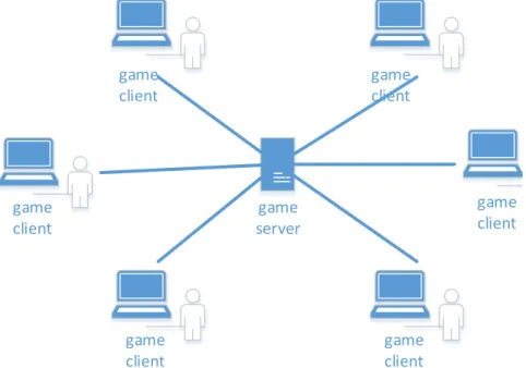
One of the most popular video game categories is the first-person shooter (FPS) [32] which is centered around guns and other weapon-based combat in a first-person perspective. Most of FPS games feature an online multiplayer model that let players compete or cooperate with other players in one virtual 3D environment in real time. A famous FPS game is Counter-Strike in which teams of terrorists and counter-terrorists battle [33]. The Counter-Strike build the multiplayer game with a client-server network model shown as Figure1.8. It’s a star network topology in which the central hub node hosts the game server, all leaf nodes are game clients. During the game, the server collects and synchronizes data to all clients and tries to enforce all game players sharing the same players status. The advantage of the client-server network model is that game clients can join or leave without disturbing the network. Counter-Strike is very fast paced, delay sensitive, and has the capacity to host tens of players in one virtual world. It relies on UDP protocol with high packet rate, short packet size and short packet inter-arrive times.
game server game client game client game client game client game client game client
This dissertation will address the gaming trafffic delay problem in WiFi network. The authors in [34] studied the throughput unfairness among homogeneous types of TCP uplink and TCP downlink traffic, and proposed a solution of modifying TCP ACK segments in order to control the throughput, and as a result achieved fairness among the flows. As this solution, stands on modifying TCP ACKs which is clocked by the WiFi AP at the speed of the propagation delay (which includes both wired and wireless part of the network). The throughput of TCP is effectively reduced by this approach. On the other hand, in this dissertation, we in the first place split the TCP between the wired and wireless part, therefore the throughput of TCP is a function wireless (MAC) propagation delay only. Subsequent to the we contain the congestion control of wireless TCP’s counterpart. Intuitively our proposed approach effectively improves the TCP throughput.
The authors in [35], provided fairness among TCP uplink and TCP downlink traffic by dynamically adjusting the WiFi AP’s buffer size in a simulation environment. On the other hand, our solution of ensuring fairness developed in SDN based framework is production-ready and presents a functional proof on a real testbed. In a different work, the authors in [36] address the TCP unfairness among TCP uplink and downlink traffic by appropriately modifying 802.11e WLANs EDCF configuration to ensure fairness. This solution is effective only on a specific standard of 802.11e WiFi, and recent studies [37] have shown that the ease of 802.11e’s configurable parameters can also lead to creating selfish WiFi nodes that throttles the throughput of other nodes. On the other hand, our solution relies on higher network layer that works on wide versions of 802.11 protocols including the widely deployed relatively configuration robust 802.11b protocols.
1.5
Virtual machine live migration
Many enterprises, not only the large-market companies like Netflix and Snapchat, but also small-market technology startup companies rely in large part on the data center for computing infrastructure or business [38] [39]. These companies often impose multifarious resource demands (storage, compute power, bandwidth, latency) on the underlying infrastructure [40]. Moreover, the resource demands may change over time according to companies’ requirement. To provide an effective, flexible, security, scalable, energy efficiency approach to manage the data center resources, the data center visualization technology is proposed and implemented in the current data centers like AWS from Amazon, Azure from Microsoft.
Data center virtualization uses software or firmware called Hypervisor that virtual-izes hardware such as servers, switches, links to be virtual machines, virtual switches, and virtual links. For example, a physical machine (server) can be virtualized as multiple independent VMs with different hardware capacities and operating systems. One of the powerful features provided by virtualization is Virtual Machine (VM) live migration, which facilitates moving workloads within the infrastructure to bring multiple benefits such as higher performance, improved manageability and fault tol-erance. Moreover, live migration of VMs often allows workload movement with neg-ligible downtime, minimal impact on workload, and no disruption of network connec-tivity [41] [42].
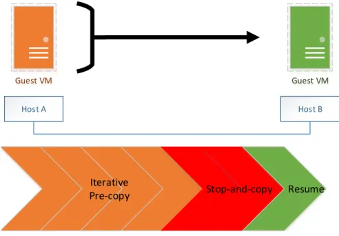
Clark et at [43] proposed a VM live migration system which transfers Memory, storage and application status (CPU state, registers,non-pageable memory) of the virtual machine from the original server to the destination. The system handles the live migration by two main techniques, Pre-copy memory migration, and Stop-and-copy memory migration shown as Figure 1.9.
pages from source to destination while the VM is still running on the source. The updated memory pages during this process are re-copied until page dirtying rate is faster than the rate of copy. In Stop-and-copy memory migration, it transfers the remaining memory pages and application status to the destination, then stops the original VM and resume on the destination.
Guest VM Guest VM Host A Host B Resume Stop-and-copy Iterative Pre-copy
Figure 1.9: VM Live Migration Pre-copy and Stop-and-copy phase
This dissertation will optimize the scheduling of VM live migration problem. The cost of VM migration has been defined in different ways in terms of a combination of network, physical server and application performance. However, some of them did not consider the application performance degradation or some of them didn’t consider the total performance degradation for all VMs. Liu at el. [44] defined total VM migration cost as a synthesized formula that integrates migration latency, total network traffic during migration, application downtime and energy cost. They evaluated their model with a real testbed for 8 VMs and did not consider the application performance degradation during the migration. Breitgand et al. [45] defined the cost as the portion of the requests to the VM that are not satisfied by their deadline. They found out that the more bandwidth the migration program uses, the faster the migration
will finish but more requests will miss the deadline. Fei at el. [46] proposed an interference-aware VM live migration strategy where the interference is defined as the performance degradation that the migrating VM imposes on other VMs hosted on the same source or destination server. The interference-aware strategy they proposed for making decisions on which VMs are to be migrated comes from an empirical study. Mann et al. [47] proposed a system named Remedy that uses a cost estimation model to minimize the cost of VM live migration, where cost is the network traffic that is generated due to migration. They assume that the destinations for the VMs are not known apriori and tries to relocate VMs in such as to reduce the network traffic.
1.6
Contributions of this dissertation
SDN is one of the most significant innovation in the networking field in recent times. This dissertation proposes a TCP join and split protocol on SDN platform to improve the performance of TCP. This protocol is extended to improve TCP fairness in Smart Grid Networks and to reduce delay in gaming traffic on WiFi networks. SDN is also maturing rapidly in Data Center networks which provide virtual infrastructure for the organization. This dissertation addresses the performance of virtual machines (VMs) live migration by proposing a Mixed Integer Linear Programming (MILP) model and a heuristic algorithm which exploits the TCP join and split protocol. The main contributions of this dissertation:
1. Developed and implemented a novel ’join and split’ TCP framework based on SDN that seamlessly joins and splits TCP flows to achieve better performance. Linked-ACK concept is proposed to maintain the TCP end-to-end semantics, and effectively control the buffer usage of the proxy network points. Provide a platform to offload TCP fine tuning from clients and servers to ’join and split’ proxy points, for better controllability [20] [48].
2. We propose a novel SDN-based aggregation-cum-scheduling framework to im-prove fairness and as well as maintain the imim-proved TCP throughput perfor-mance found in traditional aggregation-only frameworks. Unlike conceptual idea on simulation, we present a white-box design of the proposed framework by highlighting the implementation functionalities equivalent to developing a work-ing prototype. We extensively study the throughput performance and fairness with appropriate analytically model validating the experimental results [18] [49]. 3. We provide an SDN-based solution of TCP-splitting along with partially-controlled
wireless sending rate to ensure fair throughput. The fair use of TCP downlink resources allows the UDP game traffic to effectively utilize the residual shared resources such as AP buffer, which enables them to achieve reduced delay. We present an extensive performance study on the real testbeds to demonstrate the prowess of our approach. Our implementation is production ready, as it is tested on the off-the-shelf network components [50].
4. We improved the performance of virtual machines (VMs) live migration by proposing a Mixed integer linear programming (MILP) model and a heuristic algorithm which exploits the TCP join and split protocol [51].
Chapter 2
Join and spilt TCP for SDN network: design,
implementation and evaluation
2.1
Introduction
Today’s Internet is constantly growing with the addition of new sets of applications and devices. A network increasing in scale should also renew and reinvent its core functional needs and adapt to new design paradigms in order to provide improved delivery performance. Software-Defined Network (SDN) [2] is one candidate paradigm that provides effective network management and dynamic flow steering capabilities that enable engineers to build efficient network services.
While the traditional switches and routers perform simple packet routing and forwarding, the SDN-enabled switches of today, on the other hand, can intelligently forward as well as dynamically steer the network traffic. Appropriate steering and management of flows in the network can be helpful in improving the delivery perfor-mance of the associated flows. In this work, we exploit SDN technologies and develop efficient frameworks to provide improved delivery performance of the network flows. To this end, we present an SDN-based end-user agnostic ’join-and-split’ framework for TCP flows, that effectively maintains end-to-end flow semantics. By end-to-end semantics, we mean that upon a successful packet delivery, an acknowledgment for a data segment comes from its original destination host, and not from any other intermediate system [52].
the beginning of this shared path. In a typical network, this may happen on a node at the network edge. For instance, geographically deployed (cellular-based) smart grid meters that send their data to different servers that serve different purposes such as monitoring, and power load balancing [53]. Another strategic point near the server-side part of the access network can form the other end-point of this shared path. Between these two join and split points, a single long TCP flow can steadily transfer the aggregated network traffic by exploiting the common congestion control mechanism of this TCP. The significant task of this framework lies in effectively synchronizing necessary information between join and split network points. To this end, we provide a control plane functionality to the join and split network points for enabling synchronized information transfer. Moreover, this framework needs to function in a seamless manner without user interference. The aggregated flow must be routed between the join and the split points of the network in a user agnostic manner.
Our framework maintains synchronized TCP session states between split point-server part of the flows, and the corresponding client-join point of the flows. TCP connections carry state information in the form of TCP options that are negotiated during the connection setup time [54], such as enable selected ACK, enable timestamp, and enable MPTCP [55]. These options are lost when the TCP flows aggregate into a single long flow. This dissertation exploits SDN controller to perform Deep Packet Inspection (DPI) [56] on each SYN segment from client, and synchronize the parsed TCP options to the split TCP point (proxy) to establish the connection with same options as required by the client.
The two proxy points in the network split the TCP flows into three non-overlapping independent flows. These separated flows will have different throughput, and unless properly handled would break the end-to-end flow semantics [57]. In this work, we propose a new concept of Linked-ACK, wherein the ACKs of server side flows are sent
along the path from the server to the client. Therefore, the clients receive ACKs only when the packet is received at the server. The Linked-ACK mechanism can help in maintaining the end-to-end flow semantics. In addition, the Linked-ACK limits the total buffered data proportional to the maximum (sender) congestion window size of the corresponding flows. In this manner, the buffers of the join and split proxy nodes are protected from a potential overflow.
While a number of recent works have been attempted to improve TCP performance by tuning the server-side TCP parameters, our framework provide the designers more controls to fine-tune the TCP flow and achieve a better performance. Thanks to the SDN technologies, with the help of SDN controller we can provide global view and control of the network information which can be appropriately utilized to improve the network performance. For instance, to support Multi-Path TCP (MPTCP), end-users are required to upgrade to compatible kernel-code. On the other hand, our framework facilitates the ’join’ proxy to be used as MPTCP proxy point and help the end-users to benefit from the advantages of MPTCP without modifying enduser side kernel codes. We believe this will provide a flexible and scalable solution for the legacy systems in the network.
In summary, the main contributions of this work are as follows:
1. Develop and implement a novel ’join and split’ TCP framework based on SDN that seamlessly joins and splits TCP flows to achieve better performance. 2. Linked-ACK concept is proposed to maintain the TCP end-to-end semantics,
and effectively control the buffer usage of the proxy network points
3. Provide a platform to offload TCP fine tuning from clients and servers to ’join and split’ proxy points, for better controllability.
2.2
System Design and Implementation
Controller client2 client1 client3 server Proxy2 switch2 Proxy1 switch1 SDN Data Plane SDN Control PlaneFigure 2.1: System Model. Clients, switches and proxies are wired connected. SDN controller connects to both switches and is expanded to connect to both switches
Figure 2.1 shows the system model used throughout the dissertation. Each switch is considered to support SDN’s OpenFlow protocol. A proxy computing node is at-tached to each of the switches. An SDN controller is connected to these OpenFlow switches and proxy nodes. The controller interacts with the switches through Open-Flow protocol, and sends commands to the proxy nodes through a custom-designed application-layer protocol running over TCP network stack. Without loss of general-ity, three clients share the same path from Switch-1 to Switch-2. Each of the three clients are represented as C1, C2, and C3. The join proxy is represented as P1, and the split-proxy is represented as P2. The server are represented as ’S’.
2.3
SDN-based TCP Join and Split Framework
In our framework, the TCP flows from each of the clients are combined to form a long TCP flow along a shared path of the network. The SDN controller generates a Unique IDentification (UID) number, and associates it to each of the flows to be aggregated. The join-proxy attaches the UID to each received data, and sends it to the split-proxy node. The received data on split-proxy can split the flows properly with the help of UID. As shown in Fig. 1, proxy1 joins TCP flows originated from three different clients, namely C1, C2, and C3. Proxy2 splits the flow from each client, and sends them to the server.
Clients and the server need not necessarily learn any information from the network. To make the join-proxy and split-proxy transparent to both clients and the server, the SDN controller is programmed to setup flow tables to create fake the TCP connections between clients and join-proxy node, and subsequently between the split-proxy and the server. While the clients assume that they are transmitting data to the server, the data is actually sent to join-proxy node. A simple join-and-split framework has been presented in [20]. In this join-and-split framework, we need to ensure that the end-to-end semantics are maintained. Each TCP connection from every client to the server is divided into three individual TCP connections at the join and split proxy points. Each of these individual TCP connections adjusts the throughput in its own path, and maintains its own TCP states. Typically, as incoming flow rate is higher than the output rate at the proxy node, it creates an unstable queue. Therefore, it is necessary to maintain the end-to-end semantics, and also maintain queue stability. In this dissertation, we propose a "Linked-ACK" to link the ACKs of three individual TCP flows through custom-defined Open- Flow protocol in the switches.
Controller
Step2:
1) Generate new Unique ID (UID) of C1 to S
2) Generate new Source Transport (NSrcPort) of C1 to S
Step3: Send 1) Source IP 2) Source Port 3) UID
Step5:
Insert Flow table: Fake TCP Connection C1 to S switch to C1 to P1
Step6:
Insert Flow table: Fake TCP Connection P2 to S switch to C1 to S Proxy2 switch2 Proxy1 switch1 Step1: Send C1 to S Step4: Send 1) Source IP 2) Source Port 3) UID 4) NSrcPort SDN Control Plane
Figure 2.2: SDN join and split control plane. When a new SYN segments come to switch, the SDN control plane execute the program following the step 1 to 6
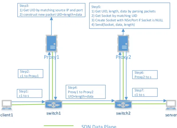
client1 server Proxy2 switch2 Proxy1 switch1 SDN Data Plane Step1: c1 to s Step2: c1 to Proxy1 Step3:
1) Get UID by matching source IP and port 2) construct new packet UID+length+data
Step4: Proxy1 to Proxy2 UID+length+data
Step5:
1) Get UID, length, data by parsing packets 2) Get Socket by matching UID
3) Create Socket with NSrcPort if Socket is NULL 4) Send(Socket, data, length)
Step6: Proxy2 to s
Step7: c1 to s
Figure 2.3: SDN join and split data flow initiation using TCP SYN segments
2.3.1 SDN-based TCP join and split
SDN supports both proactive and reactive ways of flow routing. Proactive way pop-ulates flow tables ahead of the traffic coming from the switch. On the other hand, the reactive way handles the flows ’on the fly’ depending on the information provided by the incoming flows. In our work, we consider reactive way of routing the flows. Without loss of generality, we consider that the routing table entries directing flows from, and to the (join and split) proxy nodes are pre-installed. The first segment of the incoming TCP flow from each client is forwarded to the SDN controller for analysis. The sequence of steps in the flow table setup process is shown in Fig 2.2. Switch-1 forwards the first packet (TCP SYN packet) from C1 (destined towards S) to the SDN controller.
The SDN controller analyses the received segment, extracts the client’s informa-tion, and distributes this information to the split and join proxy points. The SDN
controller then generates a UID, and creates a new TCP transport (namely, NSrc-Port) between the split-proxy point and the server, which is shown in step2 in the Fig 2.2. In a special case, when the new flow is one of the subflows of an MPTCP flow, they would share the same UID. The UID with associated flow information is the key component used in splitting and joining of flows. While a standard (out-of-the-box) SDN controller lacks any control of the proxy, we extend the SDN control plane func-tionality to allow the controller to manage the proxies attached to each OpenFlow switch with a custom application protocol developed over TCP.
After analyzing the SYN packet, the controller computes the routing path and creates a fake TCP connection between the client and join-proxy point. To this end, a flow table entry substitutes the server information with join-proxy point’s information in the specific fields of data link layer, network layer, and transport layer of the incoming flow from the client. This modified TCP flow can be accepted by the TCP server of join-proxy and vice versa. In a similar way, another fake TCP connection is established between split-proxy and the server. This TCP connection fakes the TCP client information (which typically comes with an arbitrary source port number assigned by the client’s OS). It is worthwhile to note that the TCP flow from split-proxy to the server with random source port can’t be associated with the client information in the SDN controller. Therefore, split-proxy starts the TCP connection with a given source port NSrcPort for SDN controller to retrieve client information.
After the flow tables are configured, the join-proxy receives data from clients and retrieves the UID and the clien’s information (i.e., source IP address, and port number). Then it constructs a new packet containing the following application layer information: "UID+length+data", where ’length’ is the total length of the constructed packet). Split-proxy point retrieves the UID and data, and pushes the data to a pre-established socket, as shown as Fig 2.3.
TCP flows, and use ’source IP and port-number’ information to identify these flows. The TCP flows come with different TCP options that needs to be handled properly when the split-proxy point establishes a new connection with the server. With the help of SDN technologies, we can perform deep-packet inspection on these packets, and forward the necessary TCP header configuration information to the split-proxy. The split-proxy point can then establish a TCP flow with same configuration as if it was an original client exchanging packets with the server (hence the name ’proxy’ points). The SDN controller is capable to inspect the application-layer information over TCP. Therefore, by extending application layer functionality, our system (in future) can also support application-layer join and split frameworks.
2.3.2 Preserving End-to-End Flow Semantics with ’Linked-ACK’
Controller
Step1: Insert Flow Table Match:
1)ACK from Proxy1 to clients Actions:
1)Fake TCP connection 2)Cache Packet
Match: ACK from Proxy2 to Proxy1
Actions:
1)Release ACK from proxy1 to clients
2)Output
switch2 switch1
Step2: Insert Flow Table Match:
1)ACK from Proxy1 to Proxy2 Actions:
1)Cache Packet
Match: ACK from s to clients Actions:
1)Fake TCP connection 2)Release ACK from Proxy2 to Proxy1 3)OutPut Proxy2 to Proxy1 If(SYN==1) skip Enqueue s to c1 s to c2 s to c3 If(SYN==1) skip Aggregated ACK + extra ACK Release ACK_Join Proxy1 to c1 Proxy1 to c2 Proxy1 to c3 If(SYN==1) skip Enqueue
Join ACK - extra ACK Release ACK_Client
SDN Data Plane SDN Control Plane
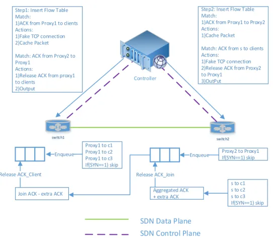
Figure 2.4: Linked-ACK. It shows the ACK collection, caching and distribution with relative installed flow tables
In this section, we describe the "Linked-ACK" framework that we have developed to maintain the end-to-end semantics of the flows. As the TCP flow is split into 3 independent TCP flows, each of the resultant split flows will have its own TCP congestion state, and throughput rate. Assuming the client is sending data at a constant rate, the join-proxy maintains a buffer to store the received data from the client. While a larger buffer size is expensive, a small buffer size on the other hand negatively impacts with a reduced TCP throughput.
Our proposed ’Linked-ACK’ provides a better solution, and bounds the buffer to a finite size. For brevity, let us represent the different ACK messages along a server-client network path as follows: (i) The ACK message ’from server to split-proxy’ be represented as ACK split, the ACK message from ’split-proxy to join split-proxy’ be represented as ACK join, and the ACK message from ’join-proxy to client’ be represented as ACK client. Our ’Linked-ACK’ framework operates in a lock-step fashion wherein the ACK join is not released until its associated ACK split packet is released. In a similar way, an ACK client is received only upon the release of its associated ACK join. We customize the standard OpenFlow protocol, and add the following four actions: caching ACK join, caching ACK client, release ACK join, and release ACK client. The modified flow table entries for routing the ACK packets are shown in step1 and step2 in Fig 2.4. The ACK client is cached (instead of being released) after the fake TCP connection is established on the switch-1. This fake TCP connection directly connects to the join-proxy node. In a similar way, ACK join is cached on the switch-2.
The ACK join, and the ACK client are stored in a FIFO queue data structure, with an exception to the SYN+ACK segment which will be released immediately to complete the three-way handshake. To guarantee that no ACK segments are lost, the length of the FIFO queue is set to a size larger than the sender’s total congestion window (CWND) size. Even when sender-side CWND is large, our approach works
due to the TCP’s ’cumulative ACK’ mechanism wherein one ACK message represents the summary of received in-order bytes.
The Algorithm-1 describes the release of ACK-join segment on split proxy node to the join proxy node. We maintain an aggregated ACK (namely, aggregateACK) for all TCP-split segments. This is done because the delayed ACK has to combine several ACK responses together into a single response. As TCP uses the cumulative ACKs, our ’Linked-ACK’ releases ACKs based on the increased ACK value, not on the number of ACK segments. To this end, the IncreasedACKValue() function returns the increased ACK value by comparing ACK values with the previous ACKs. For a corner case, this function returns 0 if the ACK number is 0, which is caused by SYN or RST flag.
The extra information such as UID and length which is attached to the data message has to be taken into account in the ACK join. Therefore, a function called extraACK() adds an extra ACK value to the aggregated ACK. Subsequently, by using a loop this algorithm keeps checking for an increased ACK value in the ACK join message stored in a queue. If ACK join has smaller increased ACK value than the aggregated ACK segment, the ACKjoin is dequeued and sent to the join-proxy.
The release ACK Client function which runs on join-proxy nodes works in a similar fashion. This function releases the ACK-client messages to the clients. However, with the following difference: the added extra ACK has to be removed to tally extra (UID+length) data cached in the join-proxy node.
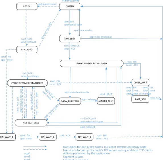
2.3.3 Linked-ACK Framework Based TCP State Machine
Fig 2.5 shows the extended TCP state diagram with Linked-ACK implemented on the proxy nodes. The traditional TCP state diagram [8] describes the different states of a TCP sender/receiver. On the other hand, our extended state diagram in Fig. 5 describes the TCP sender and TCP receiver inside the proxy aggregation node. In the
Algorithm 1: Release ACK function that runs on the split-proxy node
1: aggregateACK += IncreasedACKValue(ACK split)
2: aggregateACK += extraACK(ACK split)
3: while true do:
4: if increasedACK join > aggregateACK then
5: return
6: end if
7: aggregateACK -= increasedACK join
8: pop and send ACK join
9: end while
proxy aggregation node, the TCP receiver (server) receives TCP segments from end host (clients). An application aggregates and buffers the received segments and ACK messages, appropriately. A TCP sender maintains a connection with the TCP split proxy node. Figure 5 shows the exchange of data and ACK segments between senders and receivers. In addition to the traditional states, the following extra states are used: i) PROXY RECEIVER ESTABLISHED, ii) PROXY SENDER ESTABLISHED, iii) DATA BUFFERED, iv) RECEIVER RCVD, v) SENDER SENT, AND vi) ACK BUFFERED.
In PROXY RECEIVER ESTABLISHED state, the TCP receiver (server) accepts TCP connections from end-host clients. In the RECEIVER RCVD state the received data from the clients are pushed into a buffer, and the TCP server transitions to DATA BUFFERED. Senders in DATA BUFFERED state read data from the buffer that are fed by the receivers. In PROXY RECEIVER ESTABLISHED state, when ACK split message is received from the split proxy node, the join proxy node’s TCP client transitions to ACK BUFFERED state and releases the buffered ACK join messages to the appropriate receivers. To guarantee that no data segments are lost in the buffer, the minimum buffer size is set to the maximum receiver CWND size.
Transitions for join proxy-node's TCP client toward split proxy node
CLOSED
starting point
LISTEN
SYN_SENT
PROXY RECEIVER ESTABLISHED
PROXY SENDER ESTABLISHED
DATA_BUFFERED SENDER_SENT
rcvd: SYN; send: SYN,ACK
appl: passive open
SYN_RCVD
rcvd: SYN,ACK; send: ACK
rcvd: ACK; send: <nothing>
appl: new data in cache appl: release CLOSE_WAIT rcvd: FIN send: ACK LAST_ACK send: FIN appl: close appl: close all receivers
rcvd: ACK
FIN_WAIT_1 send: FIN
appl: close FIN_WAIT_2
rcvd: ACK rcvd: FIN send: ACK FIN_WAIT_2 rcvd: FIN send: ACK send: FIN appl: close appl:close or timeout
Transitions for join proxy node’s TCP server serving end-host TCP clients Actions performed by the application
appl:
Segment is received send: Segment is sent
rcvd:
send: FIN appl: close
ACK_BUFFERED
rcvd: ACK_split appl: release ack_join
ap p l: c ac h e A C K _ jo in s e n d : A C K _ jo in a p p l: re le as e A C K _ jo in send: SYN appl: active open
appl: new sender
appl: released send: DATA a p p l: ca ch ed A C K ap p l:n e w A C K _ sp lit re ce iv e d
Figure 2.5: TCP state diagram. This diagram show hows how Linked-ACK couples the proxy sender and receiver TCP state
2.4
Performance Evaluation and Results
The network topology shown in Fig 2.1 is used for our performance study. The consid-ered network is emulated in a Mininet network environment [5]. Hosts in the Mininet run in different network namespaces with their own set of network interfaces, IP and routing tables. Switches of Mininet support OpenFlow to enable SDN functionali-ties. Links in the Mininet emulate bandwidth, delay, and packet loss probability. The popular Floodlight [6] open-source SDN controller is used for managing flow tables in our experiments. All the TCP flows use the default Linux kernel configuration, but the MultiPath TCPs are installed from [58].
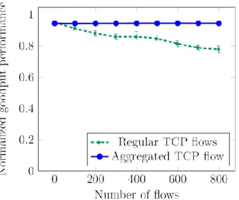
2.4.1 Aggregated TCP Goodput Performance
In this section, we show that the aggregated TCP flow can substantially improve the TCP goodput. Using the topology shown in Fig 2.1, we simulated up to a maximum of 800 concurrent TCP flows. The bottleneck link from switch-2 to the server is set to 1.5 Mbps, and all other links are configured to 1 Gbps. The switch to proxy links are considered to have unrestricted bandwidth. The average TCP goodput performance of aggregated TCP, and its non-aggregated TCP counterpart is shown in Fig 2.6. The goodput performance is shown as values normalized using the total link bandwidth. We used 95% confidence. Each test lasted for about 180 seconds. From Table 2.1, it is clear that our approach is potentially scalable as the goodput remained consistently higher with an increase in the number of flows. On the other hand, the regular TCP goodput suffered throughput degradation with an increase in the number of flows. Therefore, we can conclude that the aggregating TCP flows yields better TCP throughput even as the number of TCP flows increases.
Figure 2.6: Goodput comparison of aggregated TCP flows vs equivalent regular TCP flows
Table 2.1: Aggregated TCP throughput and confidential interval Flows Regular TCP throughput Aggregated TCP throughput
Mean Upper Lower Mean Upper Lower 1 0.9517 0.9518 0.9516 0.9438 0.9442 0.9435 100 0.9116 0.9178 0.9054 0.9431 0.9437 0.9425 200 0.8806 0.8987 0.8626 0.9439 0.9444 0.9434 300 0.8594 0.8769 0.8418 0.9441 0.9446 0.9437 400 0.8582 0.8907 0.8257 0.9443 0.9445 0.9441 500 0.8455 0.8669 0.8242 0.9444 0.9446 0.9443 600 0.8138 0.8338 0.7938 0.9446 0.9447 0.9444 700 0.7886 0.8028 0.7938 0.9445 0.9446 0.9445 800 0.7783 0.799 0.7576 0.9443 0.9447 0.9440
Flows : Number of concurrent TCP long flows
Mean : Mean value of TCP goodput/total bandwidth. Upper : Confidential interval upper bounder.
Lower : Confidential interval lower bounder. The confidential level is 95%.
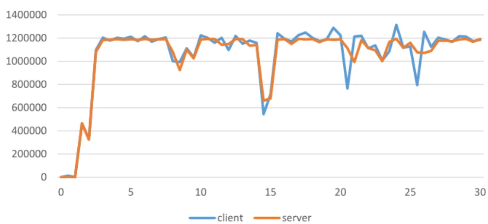
2.4.2 Linked-ACK Throughput Performance
With our Linked-ACK’ framework implementation, the throughput performance in the sub-path between ’split-proxy and the server’ path gets synchronized with the throughput along the sub-path between ’client and join-proxy’. Fig 2.7 shows the TCP throughput performance of a long TCP flow from a single client to the server with ’Linked-ACK’ framework. It is clear that both the flows have about the same throughput performance. Fig 2.8 shows the total received bytes of the flows in the respective sub-paths of client to join-proxy, and split-proxy to server. It is clear that these flows have almost the same number of total received bytes, which indicates the fact that they are well synchronized.
0 200000 400000 600000 800000 1000000 1200000 1400000 0 5 10 15 20 25 30
Linked-ACK Throughput Byte/s
client server
Figure 2.7: Linked-ACK throughput of the client to the join-proxy (show as client) the split-proxy to the server (show as server). These two flows synchronized by Linked-ACK.
2.4.3 Proxy Buffer Analysis
Fig 2.9 shows a time plot of a client’s congestion window size and the buffer sizes of join-proxy and split-proxy nodes. The client congestion window size is usually higher than the buffer size of each proxies. By exploiting TCP’s flow control mechanism, the proxy nodes can limit the maximum receiver window size to control the sender