Nonlinear Precoding for Phase-Quantized Constant-Envelope Massive
MU-MIMO-OFDM
Downloaded from: https://research.chalmers.se, 2019-05-11 12:02 UTC
Citation for the original published paper (version of record):
Jacobsson, S., Castaneda, O., Jeon, C. et al (2018)
Nonlinear Precoding for Phase-Quantized Constant-Envelope Massive MU-MIMO-OFDM
2018 25TH INTERNATIONAL CONFERENCE ON TELECOMMUNICATIONS (ICT): 367-372
http://dx.doi.org/10.1109/ICT.2018.8464896
N.B. When citing this work, cite the original published paper.
research.chalmers.se offers the possibility of retrieving research publications produced at Chalmers University of Technology. It covers all kind of research output: articles, dissertations, conference papers, reports etc. since 2004.
research.chalmers.se is administrated and maintained by Chalmers Library
Nonlinear Precoding for Phase-Quantized
Constant-Envelope Massive MU-MIMO-OFDM
Sven Jacobsson
1,2, Oscar Castañeda
3, Charles Jeon
3, Giuseppe Durisi
1, and Christoph Studer
31Chalmers University of Technology, Gothenburg, Sweden 2Ericsson Research, Gothenburg, Sweden
3Cornell University, Ithaca, NY, USA
Abstract—We propose a nonlinear phase-quantized constant-envelope precoding algorithm for the massive multi-user (MU) multiple-input multiple-output (MIMO) downlink. Specifically, we adapt the squared-infinity norm Douglas-Rachford splitting (SQUID) precoder to systems that use oversampling digital-to-analog converters (DACs) at the base station (BS) and orthogonal frequency-division multiplexing (OFDM) to communicate over frequency-selective channels. We demonstrate that the proposed SQUID-OFDM precoder is able to generate transmit signals that are constrained to constant envelope, which enables the use of power-efficient analog radio-frequency circuitry at the BS. By quantizing the phase of the resulting constant-envelope signal, we obtain a finite-cardinality transmit signal that can be synthesized by low-resolution (e.g., 1-bit) DACs. We use error-rate simulations to demonstrate the superiority of SQUID-OFDM over linear-quantized precoders for massive MU-MIMO-OFDM systems.
I. INTRODUCTION
Massive multi-user (MU) multiple-input multiple-output (MIMO) equips the base station (BS) with a large number of antenna elements and serves tens of user equipments (UEs) simultaneously and in the same frequency band [1], [2]. While massive MU-MIMO is expected to be a key technology component of fifth-generation (5G) wireless networks, scaling traditional radio frequency (RF) front-end architectures to BSs with hundreds of antenna elements leads to a prohibitive growth in circuit power consumption, system costs, and hardware complexity. Hence, a successful deployment of massive MU-MIMO requires inexpensive, power-efficient, and low-complexity hardware components, which, in turn, will limit the capacity of the system due to signal-quality degradation. A. Constant-Envelope and Phase-Quantized Precoding
In the massive MU-MIMO downlink (the BS transmits data to the UEs), precoding must be used to reduce MU interference. Unfortunately, precoding typically generates time-domain sig-nals with high peak-to-average power ratio (PAR) [3]; this fact is further aggravated in systems that use orthogonal frequency-division multiplexing (OFDM) to facilitate communication over wideband frequency-selective channels [4]. For such high-PAR The work of SJ and GD was supported in part by the Swedish Foundation for Strategic Research under grant ID14-0022, and by the Swedish Governmental Agency for Innovation Systems (VINNOVA) within the competence center ChaseOn. SJ’s research visit at Cornell was sponsored in part by Cornell’s College of Engineering. The work of OC, CJ, and CS was supported by Xilinx, Inc. and by the US National Science Foundation (NSF) under grants ECCS-1408006, CCF-1535897, CAREER CCF-1652065, and CNS-1717559.
waveforms, one has to operate the power amplifiers (PAs) in the linear regime to prevent significant signal-quality degradation. This results in high PA power consumption [4].
To mitigate the high-PAR issue, a constant-envelope precoder for the massive MU-MIMO-OFDM case was proposed in [5]; its design ensures that the precoded signal has equal amplitude on all antennas (and, hence, zero PAR). This precoder enables PAs to operate in the nonlinear regime, allowing for energy-efficient analog circuitry. Recently, the authors of [6] designed a precoder for the frequency-flat case that outputs a constant-envelope signal constrained to only eight phases. This precoder requires the digital-to-analog converters (DACs) at the BS to generate only eight phase outputs, which enables the use of power-efficient converter architectures, and reduces the interconnect data rates between the baseband-processing unit and the radio unit at the BS.
B. 1-Bit Precoding
Motivated by potential power savings and reduced intercon-nect data rates, the use of 1-bit DACs in the massive MU-MIMO downlink has recently attracted significant attention. Specifically, so-calledlinear-quantized precoders (i.e., linear precoding followed by quantization) have been recently pro-posed for precoding in massive MU-MIMO-OFDM systems that use oversampling DACs [7], [8]. These precoders achieve low bit-error rates (BERs) and high sum-rate throughputs over frequency-selective channels with OFDM, despite the adverse impact of the 1-bit DACs.Nonlinear precoders, where the precoder depends on the instantaneous realizations of the information symbols, are known to significantly outperform linear-quantized precoders (see, e.g., [9]–[15]), but have, until recently, been analyzed exclusively for frequency-flat channels and single-carrier transmission.1
C. Contributions
We propose a nonlinear phase-quantized constant-envelope precoder for the massive MU-MIMO-OFDM downlink operat-ing over frequency-selective channels. Our precoder builds upon the squared-infinity-norm Douglas-Rachford splitting (SQUID) algorithm put forward in [11, Sec. IV-B]. In contrast to previous works [9]–[15], which focus on the case of Nyquist-rate sam-pling 1-bit DACs and on the frequency-flat case, the proposed
1See, however, [16] for a recent result on the frequency-selective case with
det.
frequency-selective wireless channel
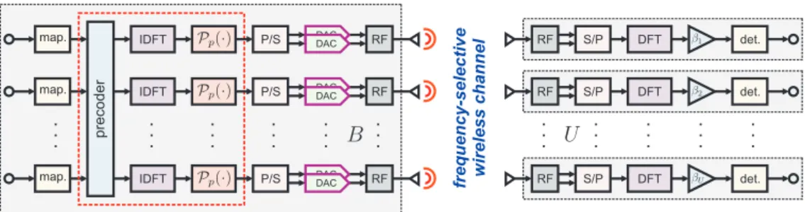
. . . RF RF RF . . . . . . . . . DAC DAC DAC DAC DAC DAC P/S P/S P/S . . . IDFT IDFT IDFT . . . precoder map. . . . DFT DFT DFT . . . S/P S/P S/P . . . RF RF RF . . . map. map. det. det. . . .
Fig. 1. Overview of the considered massive MU-MIMO-OFDM downlink system. Left: BS withBantennas performs precoding in the frequency domain, transforms the precoded vector into time domain, and maps its entries to the set of outcomes supported by the transcoder in the DACs. The dashed red box indicates the operations carried out by the nonlinear phase-quantized constant-envelope precoder. Right:Usingle-antenna UEs.
nonlinear precoder, which we shall refer to as SQUID-OFDM, is capable of supporting oversampling DACs and OFDM. We characterize the computational complexity of SQUID-OFDM and demonstrate its efficacy via numerical simulations. D. Notation
Lowercase and uppercase boldface letters denote vectors and matrices, respectively. The M × N all-zeros matrix and the M × M identity matrix are denoted by 0M×N
and IM, respectively. The unitary N ×N discrete Fourier
transform (DFT) matrix is denoted by FN. The `∞-norm
of a = [a1, . . . , aM]T is kak∞ = max`=1,...,M|a`|; the `f∞ -norm iskak f ∞= max k<{a}k∞,k={a}k∞ . We usekak2 andkAkF to denote the`2-norm of vectoraand the Frobenius
norm of matrixA, respectively. IfAis anM×N matrix, then vec(A) is an M N-dimensional vector obtained by column-wise vectorization of A. The phase ofa∈C is denoted by
arg(a); the sign of r∈Ris denoted bysgn(r)∈ {−1,+1}. The floor functionbrcproduces the largest integer less than or equal tor. The complex-valued circularly symmetric Gaussian distribution with covariance matrix K ∈CM×M is denoted
byCN(0M×1,K). The expected value of AisE[A].
II. SYSTEMMODEL
We consider a single-cell massive MU-MIMO-OFDM down-link system as illustrated in Fig. 1. The system operates over a wideband channel where OFDM is used to deal with the selectiveness in frequency of the channel. Let B denote the number of BS antennas andU the number of single-antenna UEs. At the BS, the frequency-domain information symbols are mapped to the antenna array by a precoder. At each BS antenna, the precoded signal is mapped to time domain through an inverse discrete Fourier transform (IDFT) before being passed to a pair of finite-resolution DACs, which generate the in-phase and quadrature components of the transmitted time-domain signal. For simplicity, we ignore other RF impairments and assume perfect synchronization between the BS and the UEs. A. Channel Input-Output Relation
Under the above assumptions, the received signalyn ∈CU
at theU UEs can be written as
yn= L−1
X
`=0
H`xn−`+wn (1)
at discrete time instants n= 0, . . . , N −1. Here, xn is the
B-dimensional transmit signal at discrete timenandN is the number of samples per OFDM symbol (the size of the IDFT). The vectorwn∼ CN(0U×1, N0IU)denotes the i.i.d. additive
white Gaussian noise (AWGN) at the UEs at discrete timen. Here, N0 is the noise power and SNR = 1/N0 defines the signal-to-noise ratio (SNR). The matrix H` ∈CU×B is the `th tap of the frequency-selective channel (`= 0, . . . , L−1). We assume that the realizations of{H`}L`=0−1 remain constant for the duration of each OFDM symbol and that they are perfectly known to the BS. Let X= [x0, . . . ,xN−1]T,Y=
[y0, . . . ,yN−1]T, andW= [w0, . . . ,wN−1]T. Furthermore, we let Xb = XFHN, Yb = YFNH, Wc = WFHN, and Hbk =
PL−1
`=0 H`e−jk
2π
N`. A cyclic prefix of lengthL−1is prepended
to the transmit signal at the BS. After removing the cyclic prefix and after a DFT at the UEs, the received signal at theU UEs and on the kth subcarrier can be written as
ˆ
yk=Hbkxˆk+ ˆwk (2)
fork= 0, . . . , N−1. Here,xˆk,yˆk, andwˆk correspond to the
kth column ofXb,Yb, andWc, respectively.
B. Precoding, Quantization, and OFDM Parameters
We use the disjoint sets I and G, where |I|+|G| =N, to denote the set of subcarriers associated with information symbols (occupied subcarriers) and zeros (guard subcarriers), respectively. We let S = |I| be the number of occupied subcarriers and define N/S as the oversampling ratio. Let
sk = [s1,k, . . . , sU,k]T denote the symbol vector associated
with the kth subcarrier (k = 0, . . . , N −1). We assume that su,k ∈ O for all k ∈ I and that su,k = 0 for all
k∈ G. Here,O represents a quadrature amplitude modulation (QAM) constellation (e.g., 16-QAM),.
The precoder uses the available transmit-side channel-state information to map the symbolsS= [s0, . . . ,sN−1]∈ OU×N, to the transmitted signal X, which must satisfy the average power constraintES
kXk2
F
=S. Due to the finite resolution of real-world DACs we require that X∈ XB×N
p , whereXp
is the set of values that are supported by the DACs. We shall assume that Xp is a constant-envelope alphabet and letp >0
be the number of phase bits, so that 2p is the number of
Furthermore, we let|x|2=P
ant,x∈ Xp. Here,Pant=S/(BN)
is the per-antenna transmit power, which ensures that the average power constraint is satisfied. For p < ∞, the mth element (m= 0, . . . ,2p−1) of the setXp is hence given by
(Pant)1/2ej(π+2πm)/2 p
. We letX∞={x∈C:|x|2=Pant}.
In this paper, we shall benchmark the performance of our nonlinear precoding algorithm, SQUID-OFDM, against the linear Wiener-filter (WF) precoder [17] given by
XWF=Pp
b
ZWFFHN, (3) where the kth column ofZbWF is given by
ˆ zWFk = 1 βWFHb H k b HkHbHk +U N0IU −1 sk (4) for k∈ I, and byˆzWF
k =0B×1 fork∈ G. Here, the constant
βWF∈
R+ ensures thatES[kZbWFFHNk2F] =S. Prior to
trans-mission, the time-domain precoded signal ZbWFFHN in (3) is
quantized by the functionPp(·) :CB×N → XpB×N, which is
applied entry-wise to the matrix XWF, so that the transmitted
signal matches the transcoder in the DACs. Specifically,
Pp(z) = (√ Pante j2π 2p j2parg(z) 2π k +1 2 , p <∞ √ Pantejarg(z), p=∞. (5) Note that for the2-phase-bit case (p= 2), we retrieve from (5) the 1-bit-DAC setup studied in [8]. There, the in-phase and quadrature components of the per-antenna transmitted signal are generated independently by a pair of 1-bit-DAC and
P2(z) =
r Pant
2 (sgn(<{z}) +jsgn(={z})). (6)
The 1-phase-bit case (p= 1), on the other hand, corresponds to the case when there is onlya single1-bit DAC per antenna, i.e., the transmitted signal has no in-phase component.
III. NONLINEARCONSTANT-ENVELOPEPRECODING
As in [11], [12], we focus on a nonlinear precoding strategy that minimizes the mean square error (MSE) at the UEs. Let MSEu,k=Ewu,k
|su,k−βyˆu,k|2
denote the MSE for theuth UE and on thekth subcarrier. Here, yˆu,k is theuth element
ofyˆk andβ ∈R+ is a constant that takes into account the
channel gain. With these definitions, we write the sum-MSE over theU UEs and over theS occupied subcarriers as
U X u=1 X k∈I MSEu,k= X k∈I Ewˆk ksk−βyˆkk22 (7) =X k∈I ksk−βHbkˆxkk22+β 2U SN 0. (8)
Recall thatxˆk is thekth column ofXb. We can now define the
sum-MSE-optimal precoding problem (PP) as follows:
(PP) minimize X∈XB×N p , β∈R+ P k∈I ksk−βHbkxˆkk22+β2U SN0 subject to X=XFb HN. (9)
For constant-envelope signals that adhere to the average power constraint, it holds that kvec(X)k2
∞ = Pant, and the
problem (PP) can equivalently be written as minimize X∈XB×N p , β∈R+ P k∈I ksk−βHbkˆxkk22+β 2γkvec(X)k2 ∞ subject to X=XFb HN, (10)
whereγ=BU N N0. Proceeding analogously to [11, Sec. IV-B], by setting Bb = βXb and by dropping the nonconvex
constraint X ∈ XB×N
p , we obtain the following convex
relaxation of the problem in (10), which we denote by(P`2
∞): (P`2∞) minimize b B∈CB×N X k∈I ksk−Hbkbˆkk22+γkvec BFb HN k2 ∞. (11)
Here, bˆk is thekth column ofBb. Let BbP`
2
∞ andβP`2∞ denote the optimal solutions to the problem (P`2∞). We obtain the desired matrixXP`2∞ by convertingBbP`2∞ to time-domain and by mapping the resulting matrix to the setXB×N
p using (5), i.e., XP`2∞ =P p BbP` 2 ∞FH N . (12)
In Section III-A, we will show that the problem (P`2
∞) can be
solved efficiently. Note that for the 2-phase-bit case, it holds that kvec(X)k2
∞ = 2kvec(X)k2 f
∞. In this case, it turns out
that one achieves better performance by solving instead the following optimization problem, which we denote by (P`2
f ∞): (P`2 f ∞)minimize b B∈CB×N X k∈I ksk−Hbkbˆkk22+ 2γkvec BFb HN k2 f ∞. (13)
We shall discuss the implications of this slight modification of the precoding problem in the next section.
A. SQUID-OFDM Precoding
Douglas-Rachford splitting [18] is an efficient iterative scheme to solve convex optimization problems of the form
minimize b B∈CB×N f Bb +g Bb , (14)
wheref(·)andg(·)are closed convex functions, which have proximal operators [19] defined as follows:
proxf(V) = arg min b B∈CB×N
f(Bb) +12kBb −Vk2F (15)
proxg(V) = arg min b B∈CB×N
g(Bb) +12kBb −Vk2F. (16)
By starting at an arbitrary Bb(0) andCb(0), Douglas-Rachford
splitting solves problems of the form (14) exactly [20] by repeating for t= 1, . . . , T, whereT is the maximum number of iterations, the following iterative procedure:
b A(t)=proxf2Bb(t−1)−Cb(t−1) (17) b B(t)=proxgCb(t−1)+Ab(t)−Bb(t−1) (18) b C(t)=Cb(t−1)+Ab(t)−Bb(t). (19)
We now outline the SQUID-OFDM precoder, which builds upon the SQUID precoder proposed in [11, Sec. IV-B] and
performs Douglas-Rachford splitting to solve the problems (P`2
∞) and (P`2 f
∞). Specifically, SQUID-OFDM extends SQUID
to support OFDM, oversampling DACs, and arbitrary constant-envelope alphabets. Let f Bb
= P k∈Iksk−Hbkbˆkk22. For the problem (P`2∞),g Bb =γkvec BFb HN k2
∞. For the
prob-lem (P`2 f ∞), g Bb = 2γkvec BFb HN k2 f
∞. In both cases, the
proximal operator for g(·) in (16) can computed using [11, Alg. 1]. For the proximal operator of f(·), we note that the objective function in (15) is separable in the columns of Bb
and that thekth column of Ab(t) in (17) can be computed as
ˆ a(kt)=HbHkHbk+12IB −1 b HH k sk+ ˆb (t−1) k − 1 2ˆc (t−1) k (20) = IB−QkHbk 2ˆb (t−1) k −ˆc (t−1) k +dk (21)
fork∈ I, andak(t)= 2ˆb(kt−1)−ˆc(kt−1)fork∈ G. Here,a(kt)is thekth column ofAb(t)andc
(t)
k is the kth column ofCb(t). To
derive (21), we used the Woodbury matrix identity to reduce the dimension of the inverse and to speed up computations by precomputing, fork∈ I, the matrixQk∈CB×U and the
vectordk ∈CB, which are defined as follows:
Qk =HbHk b HkHbHk + 1 2IU −1 (22) dk = 2 b HkHsk−QkHbkHbHksk . (23)
We can now solve the problems (P`2
∞) and (P`2 f
∞) by using
the iterative procedure outlined in Algorithm 1.
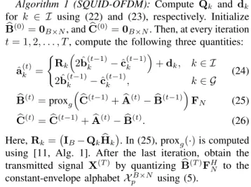
Algorithm 1 (SQUID-OFDM): Compute Qk and dk
for k ∈ I using (22) and (23), respectively. Initialize
b
B(0)=0
B×N, andCb(0)=0B×N. Then, at every iteration
t= 1,2, . . . , T, compute the following three quantities:
ˆ a(kt)= ( Rk 2ˆb(kt−1)−ˆck(t−1)+dk, k∈ I 2ˆb(kt−1)−cˆ(kt−1), k∈ G (24) b B(t)=proxg b C(t−1)+Ab(t)−Bb(t−1) FN (25) b C(t)=Cb(t−1)+Ab(t)−Bb(t). (26)
Here,Rk = IB−QkHbk. In (25), proxg(·)is computed
using [11, Alg. 1]. After the last iteration, obtain the transmitted signal X(T) by quantizing
b
B(T)FH N to the
constant-envelope alphabetXB×N
p using (5).
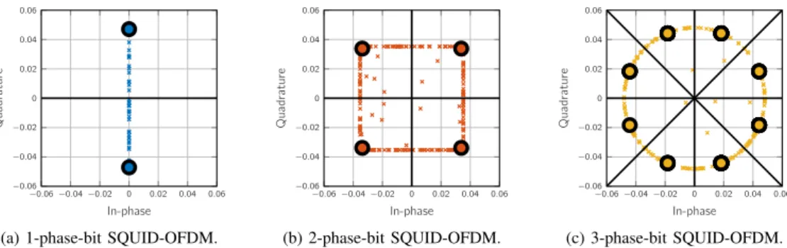
Fig. 2 shows the time-domain SQUID-OFDM output
b
B(20)FH
N afterT = 20iterations before and after quantization.
2
Fig. 2b shows the SQUID-OFDM output for the problem (P`2
f ∞)
before and after 2-phase-bit quantization.3 We see that the` f ∞
-norm constrains the SQUID-OFDM output to a box in the complex plane, which limits the error caused by the quantizer. Fig. 2c shows the output for the problem (P`2
∞) before and after
3-phase-bit quantization. In this case, the`∞-norm constrains
2The simulation parameters are given in Section IV-A. 3By settingS= 1andN= 1for the problem (P`2
f
∞), Algorithm 1 reduces
to the SQUID precoder for single-carrier transmission [11, Sec. IV-B].
TABLE I
COMPLEXITY COMPARISON BETWEENWFANDSQUID-OFDM.
Precoder Computational complexity
WF 2S 1 3U 3+BU2+ 2U2−1 3U +4B(Nlog2N−3N+ 4) SQUID-OFDM 2S 5 3U 3+ 3BU2+ 6B−2 3 U +4T B(2SU+ 2Nlog2N−5N+ 8)
the SQUID-OFDM output to a circle in the complex plane, which is suitable for quantization using three phase bits or more. Fig. 2a shows the SQUID-OFDM output for the problem (P`2
∞)
before and after 1-phase-bit quantization. Here, we slightly modified the problem to force the real part of the output to the proximal operator proxg(·) to zero. This constrains the SQUID-OFDM output to a line in the complex plane, which is suitable for quantization using only one phase bit.
B. Computational Complexity
Table I shows the computational complexity characterized by the number of real-valued multiplications for SQUID-OFDM and WF precoding. In what follows, we assume that one complex-valued multiplication requires four real-valued multiplications.
1) WF Precoding: Computing (4) exactly for all k ∈ I
using implicit Cholesky-based matrix inversion [21] requires
2S 13U3+BU2+ 2U2−1
3U
real-valued multiplications. At each antenna element, the frequency-domain precoded vector is converted to time-domain via an IDFT. Computing these IDFTs require4B(Nlog2N−3N+ 4)real-valued multiplications if the IDFTs are computed using the split-radix Fast Fourier Transform (FFT) algorithm [22, Sec. 4.3]. By adding these two numbers, we obtain the complexity reported in Table I.
2) SQUID-OFDM: The preprocessing step of SQUID-OFDM involves computing (22) and (23) fork∈ I. Proceeding as in [23], we find that computing Qk in (22) for k ∈ I
requires2S(53U3+ 3BU2−2
3U)real-valued multiplications. Furthermore, computing dk in (23) for k ∈ I requires an
additional 12SBU real-valued multiplications. By adding these numbers, we find that the preprocessing complexity of SQUID-OFDM is 2S 53U3+ 3BU2+ 6B−2
3
U
. Moving on to the per-iteration complexity. Computing efficiently the vectors a(kt) in (24) for k ∈ I requires 8SBU real-valued multiplications per iteration.4 Furthermore, executing [11, Alg. 1] requires4BNreal-valued multiplications, which means that computingBb(t)in (25), if the split-radix FFT algorithm
is used to compute the IDFT and DFT, requires an additional
4B(2Nlog2N −5N + 8) real-valued multiplications per iteration. Hence, the per-iteration complexity of SQUID-OFDM is 4B(2SU+ 2Nlog2N−5N+ 8).5 Finally, by adding the
4Efficiently computing the step (24) fork∈ I involves first computing
vk= 2ˆb(t −1) k −ˆc
(t−1)
k and then computingaˆ (t)
k =vk−QkHbkvk+dk.
5For the single-carrier case (i.e., whenN = 1andS = 1),
SQUID-OFDM reduces to single-carrier SQUID [11, Sec. IV-B] and the per-iteration complexity reduces to8BU+ 4Breal-valued multiplications (no split-radix FFT algorithm has to be computed for this case).
−0.06−0.04−0.02 0 0.02 0.04 0.06 −0.06 −0.04 −0.02 0 0.02 0.04 0.06 In-phase Quadrature
(a) 1-phase-bit SQUID-OFDM.
−0.06−0.04−0.02 0 0.02 0.04 0.06 −0.06 −0.04 −0.02 0 0.02 0.04 0.06 In-phase Quadrature (b) 2-phase-bit SQUID-OFDM. −0.06−0.04−0.02 0 0.02 0.04 0.06 −0.06 −0.04 −0.02 0 0.02 0.04 0.06 In-phase Quadrature (c) 3-phase-bit SQUID-OFDM.
Fig. 2. Per-antenna SQUID-OFDM output before and after quantization for 16-QAM,T = 20,SNR= 10dB,B= 128,U= 16,S= 1200, andN= 4096. The cross-markers correspond to the output before quantization, the circles to the quantized output, and the lines to the decision regions for the quantizer.
preprocessing complexity and the per-iteration complexity, we obtain the complexity forT iterations reported in Table I. Note that the computational complexity of both SQUID-OFDM and WF precoding scaleslinearlyin the number of BS antennasB.
IV. NUMERICALRESULTS A. Simulation Parameters
Due to space constraints, we focus on a selected set of system parameters.6 Specifically, we consider the case in which the BS is equipped with B = 128 antennas and serves U = 16
UEs. We consider long-term evolution (LTE)-inspired OFDM parameters [24] withS= 1200occupied subcarriers and where
N = 4096 (the oversampling ratio is N/S = 4096/1200≈
3.41). The subcarrier spacing is∆f = 15kHz and the sampling rate is fs = N∆f = 61.44 MHz. The set of occupied
subcarriers is I ={1,2, . . . ,600,3497,3498, . . . ,4096} and the set of guard subcarriers isG ={0,1, . . . ,4096}\ I. The entries of{H`}L`=0−1 are i.i.d.CN 0,1/L
(Rayleigh fading). The number of taps is L= 4. We furthermore assume that the
uth UE (u= 1,2, . . . , U) scales the received signal for each OFDM symbol by [12] βu= 1 q 1 S P k∈I|yˆk| 2 −N0 , (27)
to obtain an estimate˜su,k=βuyˆu,k of su,k for k∈ I.
B. Convergence and Complexity
We start by investigating the convergence of SQUID-OFDM for the 2-phase-bit case. Fig. 3 shows the complementary cumulative distribution function (CCDF) of the error-vector magnitude (EVM), with 16-QAM signaling forSNR= 10dB. Here, the EVM for theuth UE (u= 1, . . . , U) is defined as
EVMu= v u u t P k∈I su,k−βuhˆTu,kxˆk 2 P k∈I|su,k| 2 , (28)
wherehˆTu,k is theuth row ofHb and whereβu is given by (27).
For reference, we also show the CCDF of the EVM with WF precoding for the 2-phase-bit case and for theinfinite-resolution
6Our simulation framework is available for download from GitHub
(https://github.com/quantizedmassivemimo/1bit_precoding_ofdm). 0 5 10 15 20 25 30 35 10−3 10−2 10−1 100 1 3 5 10 20 100 EVM [%] CCDF 2-phase-bit WF 2-phase-bit SQUID Inf.-res. WF
Fig. 3. CCDF of the EVM with 16-QAM;SNR= 10dB,B= 128,U= 16,
S= 1200, andN= 4096. The number next to the CCDF curves corresponds to the number of iterations for SQUID-OFDM.
case (i.e., when XWF =
b
ZWFFH
N ∈ CB×N), respectively.
Interestingly, we see that SQUID-OFDM with only one iteration already significantly outperforms WF precoding in terms of EVM. Furthermore, we see from Table I that for T = 1, the complexity of SQUID-OFDM is just about 3 times higher than that of WF precoding. We also see from Fig. 3 that by increasing the number of iterations from 20to100, SQUID-OFDM attains only marginal EVM gains. In what follows, we set the number of iterations to T = 20. In this case, SQUID-OFDM requires approximately 14 times more real-valued multiplications than the WF precoder, assuming the parameters given in Section IV-A.
C. Error-Rate Performance
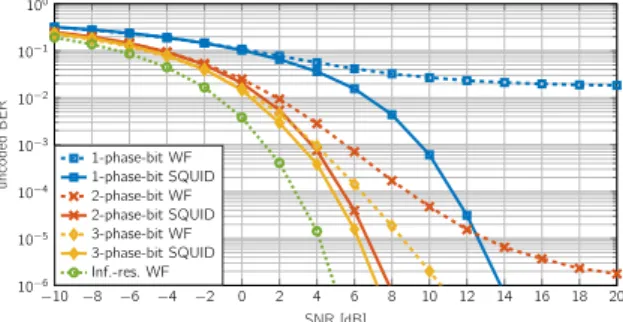
1) Uncoded BER: Fig. 4a shows the uncoded BER with 4-QAM forp-phase-bit (p∈ {1,2,3}) SQUID-OFDM and WF precoding as a function of the SNR. We also show the uncoded BER with infinite-resolution WF precoding. We assume that the UEs perform symbol-wise nearest-neighbor decoding (i.e., each UE maps the received signal to the nearest constellation point in O). We note that SQUID-OFDM outperforms WF precoding for all considered values of SNR and irrespectively of the number of phase bits. Interestingly, low uncoded BERs are supported even by 1-phase-bit SQUID-OFDM.
2) Coded BER: Fig. 4b shows the coded BER with 16-QAM forp-phase-bit (p∈ {1,2,3,∞}) SQUID-OFDM as a function of the SNR. For ∞-phase-bit SQUID-OFDM, the output after the last iteration is mapped to the setXB×N
−10 −8 −6 −4 −2 0 2 4 6 8 10 12 14 16 18 20 10−6 10−5 10−4 10−3 10−2 10−1 100 SNR [dB] uncoded BER 1-phase-bit WF 1-phase-bit SQUID 2-phase-bit WF 2-phase-bit SQUID 3-phase-bit WF 3-phase-bit SQUID Inf.-res. WF
(a) Uncoded BER with 4-QAM. SQUID-OFDM outperforms WF precoding irrespectively of the SNR and the number of phase bits.
−10 −8 −6 −4 −2 0 2 4 6 8 10 12 14 16 18 20 10−6 10−5 10−4 10−3 10−2 10−1 100 SNR [dB] coded BER 1-phase-bit SQUID 2-phase-bit SQUID 3-phase-bit SQUID ∞-phase-bit SQUID Inf.-res. WF
(b) Coded BER with 16-QAM (rate-5/6 convolutional code). Low coded BERs are supported with SQUID-OFDM.
Fig. 4. Uncoded/coded BER as a function of SNR and the number of phase bits;
B= 128,U= 16,S= 1200, andN= 4096. SQUID-OFDM significantly outperforms linear precoders and approaches infinite resolution performance.
At the BS, the information bits are encoded using a weak rate-5/6 convolutional code. Each codeword is randomly interleaved over4800bits (i.e., over theS = 1200occupied subcarriers in an OFDM symbol). To detect the information bits, each UE performs soft-input max-log BCJR decoding. We note that low coded BERs are supported with SQUID-OFDM. Also, we note that 2-phase-bit SQUID-OFDM already offers performance close to that of∞-phase-bit SQUID-OFDM.
V. CONCLUSIONS
We have proposed a nonlinear phase-quantized precoder called SQUID-OFDM for the massive MU-MIMO-OFDM downlink. The precoder extends the SQUID precoder in [11] to support OFDM, oversampling DACs, and arbitrary constant-envelope alphabets. SQUID-OFDM is shown to offer superior error-rate performance to linear precoders such as WF pre-coding at an increased computational complexity (three times or higher depending on the number of algorithm iterations). The constant-envelope transmit signals generated by SQUID-OFDM enable energy-efficient PAs, which is in stark contrast to the infinite-precision WF precoder whose PAR approximately ranges between10dB and12dB. Furthermore, for 2-phase-bit SQUID-OFDM, the amount of raw data that has to be fed to the DACs is15.7Gbit/s. In contrast, a traditional system that uses high-resolution DACs, e.g.,12-bit, must sustain raw baseband data rates that exceed188Gbit/s for the parameters considered in this paper, which seems impractical.
REFERENCES
[1] F. Boccardi, R. W. Heath Jr., A. Lozano, T. L. Marzetta, and P. Popovski, “Five disruptive technology directions for 5G,”IEEE Commun. Mag.,
vol. 52, no. 2, pp. 74–80, Feb. 2014.
[2] E. G. Larsson, F. Tufvesson, O. Edfors, and T. L. Marzetta, “Massive MIMO for next generation wireless systems,”IEEE Commun. Mag., vol. 52, no. 2, pp. 186–195, Feb. 2014.
[3] C. Mollén, E. G. Larsson, and T. Eriksson, “Waveforms for the massive MIMO downlink: Amplifier efficiency, distortion, and performance,”
IEEE Trans. Commun., vol. 64, no. 12, pp. 5050–5063, Dec. 2016.
[4] S. S. Han and J. H. Lee, “An overview of peak-to-average power ratio reduction techniques for multicarrier transmission,”IEEE Wireless
Commun., vol. 12, no. 2, pp. 56–65, Apr. 2005.
[5] S. K. Mohammed and E. G. Larsson, “Constant-envelope multi-user precoding for frequency-selective massive MIMO systems,” IEEE
Commun. Lett., vol. 2, no. 5, pp. 547–550, Oct. 2013.
[6] A. Noll, H. Jedda, and J. A. Nossek, “PSK precoding in multi-user MISO systems,” inProc. Int. ITG Workshop on Smart Antennas (WSA), Berlin, Germany, Mar. 2017, pp. 57–63.
[7] S. Jacobsson, G. Durisi, M. Coldrey, and C. Studer, “Linear precoding with low-resolution DACs for massive MU-MIMO-OFDM downlink,” Sep. 2017. [Online]. Available: https://arxiv.org/abs/1709.04846 [8] ——, “Massive MU-MIMO-OFDM downlink with one-bit DACs and
linear precoding,” inProc. IEEE Global Commun. Conf. (GLOBECOM), Singapore, Singapore, Dec. 2017.
[9] H. Jedda, J. A. Nossek, and A. Mezghani, “Minimum BER precoding in 1-bit massive MIMO systems,” inIEEE Sensor Array and Multichannel
Signal Process. Workshop (SAM), Rio de Janeiro, Brazil, Jul. 2016.
[10] A. L. Swindlehurst, A. K. Saxena, A. Mezghani, and I. Fijalkow, “Minimum probability-of-error perturbation precoding for the one-bit massive MIMO downlink,” inProc. IEEE Int. Conf. Acoust., Speech,
Signal Process. (ICASSP), New Orleans, LA, USA, Mar. 2017, pp. 6483–
6487.
[11] S. Jacobsson, G. Durisi, M. Coldrey, T. Goldstein, and C. Studer, “Quantized precoding for massive MU-MIMO,”IEEE Trans. Commun.,
vol. 65, no. 11, pp. 4670–4684, Nov. 2017.
[12] ——, “Nonlinear 1-bit precoding for massive MU-MIMO with higher-order modulation,” inProc. Asilomar Conf. Signals, Syst., Comput., Pacific Grove, CA, USA, Nov. 2016, pp. 763–767.
[13] O. Castañeda, S. Jacobsson, G. Durisi, M. Coldrey, T. Goldstein, and C. Studer, “1-bit massive MU-MIMO precoding in VLSI,” IEEE J.
Emerging Sel. Topics Circuits Syst., vol. 7, no. 4, pp. 508–522, Dec.
2017.
[14] A. Li, C. Masouros, F. Liu, and A. L. Swindlehurst, “Massive MIMO 1-bit DAC transmission: A low-complexity symbol scaling approach,” Nov. 2017. [Online]. Available: https://arxiv.org/abs/1709.08278 [15] L. Landau and R. C. de Lamare, “Branch-and-bound precoding for
multiuser MIMO systems with 1-bit quantization,” IEEE Wireless
Commun. Lett., vol. 6, no. 6, pp. 770–773, Dec. 2017.
[16] A. Nedelcu, F. Steiner, M. Staudacher, G. Kramer, W. Zirwas, R. Sisava Ganesan, P. Baracca, and S. Wesemann, “Quantized precoding for multi-antenna downlink channels with MAGIQ,” inInt. ITG Workshop
on Smart Antennas (WSA), Bochum, Germany, Mar. 2017.
[17] M. Joham, W. Utschick, and J. A. Nossek, “Linear transmit processing in MIMO communications systems,”IEEE Trans. Signal Process., vol. 53, no. 8, pp. 2700–2712, Aug. 2005.
[18] P. L. Lions and B. Mercier, “Splitting algorithms for the sum of two nonlinear operators,”SIAM J. Numer. Anal., vol. 16, no. 6, pp. 964–979, Dec. 1979.
[19] N. Parikh and S. Boyd, “Proximal algorithms,”Found. Trends Optim., vol. 1, no. 3, pp. 127–239, Jan. 2014.
[20] J. Eckstein and D. P. Bertsekas, “On the Douglas-Rachford splitting method and the proximal point algorithm for maximal monotone operators,”Math. Programming, vol. 55, pp. 293–318, Apr. 1992. [21] M. Wu, B. Yin, K. Li, C. Dick, J. R. Cavallaro, and C. Studer, “Implicit vs.
explicit approximate matrix inversion for wideband massive MU-MIMO data detection,”Journal of Signal Processing Systems, Dec. 2017. [22] P. Duhamel and M. Vetterli, “Fast Fourier transforms: A tutorial review
and a state of the art,”Signal Processing, vol. 19, pp. 259–299, Apr. 1990.
[23] K. Li, R. R. Sharan, Y. Chen, T. Goldstein, J. R. Cavallaro, and C. Studer, “Decentralized baseband processing for massive MU-MIMO systems,”
IEEE J. Emerging Sel. Topics Circuits Syst., vol. 7, no. 4, pp. 491–507,
Dec. 2017.
[24] E. Dahlman, S. Parkvall, and J. Sköld, 4G: LTE/LTE-Advanced for