Optimized Profiles
for Astigmatic Refractive Surgery
Samuel Arba-Mosquera
1,2, Sara Padroni
3,
Sai Kolli
4and Ioannis M. Aslanides
3 1Grupo de Investigación de Cirugía Refractiva y Calidad de Visión, Instituto de
Oftalmobiología Aplicada, University of Valladolid, Valladolid,
2SCHWIND eye-tech-solutions, Kleinostheim,
3Emmetropia Mediterranean Eye Clinic, Heraklion,
4Moorfields Eye Hospital, London,
1Spain
2Germany
3Greece
4United Kingdom
1. Introduction
For the correction of astigmatism, many different approaches have been tested, with different
degrees of success, through the years1. Patient satisfaction in any refractive surgery,
wavefront-guided or not, is primarily dependent on successful treatment of the lower order aberrations (LOA) of the eye (sphere and cylinder). Achieving accurate clinical outcomes and reducing the likelihood of a retreatment procedure are major goals of refractive surgery. LASIK has been successfully used for low to moderate myopic astigmatism, whether LASIK is acceptably efficacious, predictable, and safe in correcting higher myopic astigmatism is less documented, especially with regard to the effects of astigmatic corrections in HOA’s.
The correction of astigmatism has been approached using several techniques and ablation profiles. There are several reports showing good results for compound myopic astigmatism using photorefractive keratectomy (PRK) and LASIK, but ablation profiles usually cause a hyperopic shift because of a coupling effect in the flattest corneal meridian. A likely mechanism of this coupling effect is probably due to epithelial remodeling and other effects such as smoothing by the LASIK flap. In cases of large preoperative amounts of astigmatism, deviations from the target refractive outcome are usually attributed to “coupling factors.” Nevertheless, the investigation of the coupling factor remains a rather difficult task, because it seems to be dependent on various factors. Individual excimer laser systems may have different coupling factors, cutting the flap could alter the initial prescription and different preoperative corneal curvatures (K-reading) may have influence on coupling factor.
2. Induction of aberrations
While for quasi-spherical corrections the focus has been moved from primary refractive
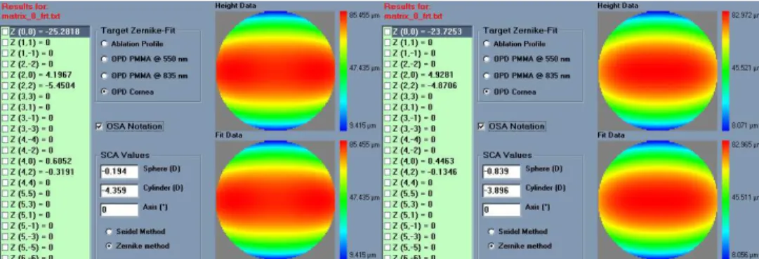
Fig. 1. Representations of the astigmatic error. Top: Topographic astigmatism measured at the corneal vertex withhin the central 3mm disc showing 4D of astigmatism. Middle left: 7mm diameter wavefront irregular astigmatism measured at the pupil centre showing 4.6D regular astigmatism with 0.4D coma and 0.3D spherical aberration. Middle right: 7mm diameter wavefront more regular astigmatism measured at the corneal vertex showing 4.6D regular astigmatism with only 0.2D coma and 0.2D spherical aberration. Bottom left: 4mm diameter refractive irregular astigmatism measured at the pupil centre showing 4.25D regular astigmatism with 0.2D coma and 0.1D spherical aberration. Bottom right: 4mm diameter refractive more rergular astigmatism measured at the corneal vertex showing 4.25D regular astigmatism with 0D coma and 0.1D spherical aberration.
astigmatism the focus mainly remained at the primary refractive outcomes, principally due
to the encountered problems as “coupling factors”5 or cyclotorsion errors38, which result in
residual astigmatism.
% Residual Astigmatism vs. Torsion error
0% 25% 50% 75% 100% 125% 150% 175% 200% 0 15 30 45 60 75 90
Torsional Error (degrees)
% R e s id u a l A s ti g m a ti s m
Fig. 2. Residual astigmatism magnitude vs. torsion error (assuming the astigmatic error and the correcting cylinder are at the same plane and are equal in dioptric power).
Refractive surgeons have been observing post-operatively a resulting hyperopic refraction on the sphere (hyperopic shift) whenever they applied a negative cylinder onto the cornea. This output sphere was not planned and depends on several factors:
- Variation for different refractive LASER systems
- Dependant on the intended negative cylinder in a non-linear relation
- Changing for sphero-cylindrical correction compared to pure cylindrical ones
Due to all these reasons, it was an issue for the surgeons to properly include this effect in their nomograms to achieve the intended refraction.
Most of the LASER manufacturers and surgeons used the “Coupling Factor”2 defined as the
averaged output sphere per single diopter of pure negative cylinder achieved.
Despite of its empirical nature, this Coupling Factor allows the surgeon to plan the treatment with reasonable success.
The hint for one of the sources of this “coupling effect” was the analysis of a pure negative cylinder case. When a pure negative cylinder is applied, the neutral axis becomes refractive, being deeper at the centre compare to the periphery.
The “Coupling Factor” is a nomogram-like “adjustment” introduced by surgeons to achieve the intended result. With the introduction of Wavefront guided ablation volumes and loss of efficiency compensation factors; these effects should be mainly compensated in the devices by refined algorithms instead of nomogrammed by the surgeon.
centre, whereas the refractive axis “shrinks,” steepening the curvature and then slightly increasing the myopic power of the axis as well as inducing aberrations. The net effect can be expressed as an unintended myopic ablation (hyperopic shift), and a small undercorrection of the astigmatic component.
Fig. 3. Effect of the hyperopic shift and coupling factor in the ablative refractive correction. Left: attempted correction. Right: simulated correction considering uncompensated reflection, projection, and geometric efficiency losses. Notice that an unintended -0.75D extra myopic spherical correction is induced, and a reduction of 0.5D in the astigmatic correction.
Several models have been proposed to compensate for those effects.
The models by Arba-Mosquera&de-Ortueta5 provide a general method to analyze the loss of
ablation efficiency at non-normal incidence in a geometrical way. The model is comprehensive and directly considers curvature, system geometry, applied correction, and astigmatism as model parameters, and indirectly laser beam characteristics and ablative spot properties. The model replaces the direct dependency on the fluence by a direct dependence on the nominal spot volume and on considerations about the area illuminated by the beam, reducing the analysis to pure geometry of impact. Compensation of the loss of ablation efficiency at non-normal incidence can be made at relatively low cost and would directly improve the quality of results.
The proposed models provide results essentially identical to those obtained with the model by
Dorronsoro-Cano-Merayo-Marcos5. Additionally, it offers an analytical expression including
some parameters that were ignored (or at least not directly addressed) in previous analytical approaches.
Different effects interact; the beam is compressed due to the loss of efficiency, but at the same time expands due to the angular “projection.” Losses of ablation efficiency at non-normal incidence in refractive surgery, may explain up to 45% of the reported increase in
aberrations. The loss of efficiency is an effect that should be offset in commercial laser systems using sophisticated algorithms that cover most of the possible variables. Parallel to the clinical developments, increasingly capable, reliable, and safer laser systems with better resolution and accuracy are required.
Corneal curvature and applied correction play an important role in the determination of the ablation efficiency and are taken into account for accurate results. However, corneal toricity and applied astigmatism do not have a relevant impact as long as their values correspond to those of normal corneas. Only when toricity or astigmatism exceeds 3 D, their effects on ablation efficiency start to be significant. Surface asphericity showed minor effects.
The loss of efficiency in the ablation and non-normal incidence are responsible for much of the induction of aberrations observed in the treatments as well as many undercorrections observed in astigmatism with major implications for treatment and optical outcome of the procedure. Compensation can be made at relatively low cost and directly affects the quality of results.
Considering this model of loss of efficiency, we have applied it for different LASER peak radiant exposures (FWHM 1mm, Gaussian profile), then we have calculated the “Coupling Factor” according to the averaged output sphere per single diopter of pure negative cylinder achieved.
Peak Radiant Exposure (mJ/cm2) Coupling Factor (%)
100 37 130 22 180 16 230 11 300 8 400 5 Table 1. Theoretical coupling factor as a function of the laser fluence.
Today, several approaches to import, visualize, and analyze high detailed diagnostic data of the eye (corneal or ocular wavefront data) are offered. At the same time, several systems are
available to link diagnostic systems for measurement of corneal and ocular aberrations6 of
the eye to refractive laser platforms. These systems are state-of-the-art with flying spot technology, high repetition rates, fast active eye trackers, and narrow beam profiles. Consequently, these systems offer new and more advanced ablation capabilities, which may
potentially suffer from new sources of “coupling” (different Zernike orders5 affecting each
other with impact on the result). The improper use of a model that overestimates or underestimates the loss of efficiency will overestimate or underestimate its compensation and will only mask the induction of aberrations under the appearance of other sources of error.
In coming years, the research and development of algorithms will continue on several fronts in the quest for zero aberration. This includes identification of sources for induction of aberrations, development and refinement of models describing the pre-, peri- and postoperative biomechanics of the cornea, development of aberration-free profiles leaving pre-existing aberrations of the eye unchanged, redevelopment of ablation profiles to
When a patient is selected for non-customized aspherical treatment, the global aim of the surgeon should be to leave all existing high-order-aberrations (HOA) unchanged because the best-corrected visual acuity, in this patient, has been unaffected by the pre-existing aberrations. Hence, all factors that may induce HOAs, such as biomechanics, need to be taken into account prior to the treatment to ensure that the preoperative HOAs are
unchanged after treatment38.
Then, in the treatments, the goals should be:
a. For aspherical treatments: no induced aberrations; a change in asphericity depending
on the corrected defocus.
b. For wavefront-guided treatments: change in aberrations according to diagnosis; change in
asphericity depending on the corrected defocus and on the C(n,0) coefficients applied. Even though the condition of stigmatism, that origins "free of aberration" verified for two points (object and image) and for a conicoid under limited conditions, is very sensitive to
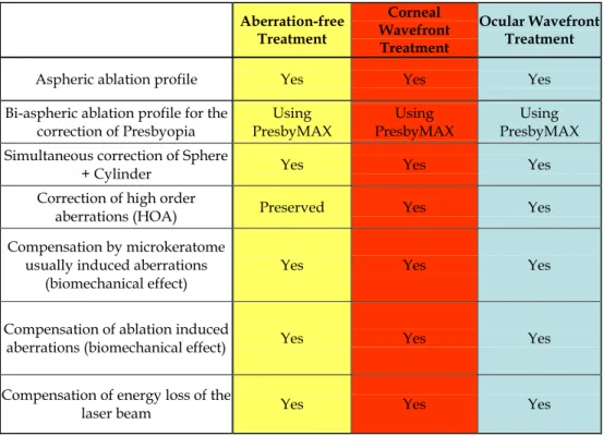
Aberration-free Treatment Corneal Wavefront Treatment Ocular Wavefront Treatment
Aspheric ablation profile Yes Yes Yes
Bi-aspheric ablation profile for the correction of Presbyopia Using PresbyMAX Using PresbyMAX Using PresbyMAX Simultaneous correction of Sphere
+ Cylinder Yes Yes Yes
Correction of high order
aberrations (HOA) Preserved Yes Yes
Compensation by microkeratome usually induced aberrations
(biomechanical effect)
Yes Yes Yes
Compensation of ablation induced
aberrations (biomechanical effect) Yes Yes Yes
Compensation of energy loss of the
laser beam Yes Yes Yes
small deviations and decentrations (a question that usually arises in refractive surgery), the goal of these profiles is not to achieve an stigmatism condition postoperatively, but rather to maintain the original HO wavefront-aberration.
The optical quality in an individual can be maximized for a given wavelength and a given distance by canceling the aberration of his wavefront and optimizing his defocus (for a single distance), but this has direct implications dramatically negative for the optical quality for the rest of wavelengths (greater negative effect the more extreme is the wavelength). However, the optical quality of a person showing a certain degree of aberration of his wavefront decreases compared to the maximum obtainable in the absence of aberration, but it has direct positive implications in the "stability" of the optical quality for a wide range for
wavelengths (which covers the spectral sensitivity of the human eye)9 and in the depth of
focus, i.e. for a range of distances that can be considered "in-focus" simultaneously. Lastly, moderate levels of wavefront-aberration favor the stability of the image quality for wider visual fields10. In such a way, there are, at least, three criteria (chromatic blur, depth of focus,
wide field vision) favoring the target of leaving minor amounts of not clinically relevant aberrations (the proposed “aberration-free” concept).
With simple spherical error, degradation of resolution begins for most people with errors of 0.25 D. A similar measure can be placed on the error due to cylinder axis error.
Optimized patterns for refractive surgery aiming to be neutral for aberrations together with the consideration of other sources of aberrations such as blending zones, eye-tracking, and corneal biomechanics having close-to-ideal ablation profiles should improve the clinical results decreasing the need for nomograms, and reducing the induced aberrations after surgery.
4. The astigmatic refraction problem
Classical ametropias (myopia, hyperopia and astigmatism) are, similarly to aberration errors, differences to a reference surface, and are included in the, more general, wavefront error. However, classical ametropias are used to be described, not in units of length, but in units of optical refractive power.
It is, then, necessary to find a relationship between wavefront error magnitudes and classical ametropias11,12,13,14,15. This relationship is often called “objective wavefront refraction”:
The quadratic equivalent of a wave-aberration map can be used as a relationship between wavefront-error magnitudes and classical ametropias. That quadratic is a sphero-cylindrical surface, which approximates the wave aberration map. The idea of approximating an arbitrary surface with a quadratic equivalent is a simple extension of the ophthalmic technique of approximating a sphero-cylindrical surface with an equivalent sphere.
Several possibilities to define this relationship can be found in the literature:
- Objective wavefront refraction from low order Zernike modes at full pupil size16
- Objective wavefront refraction from Seidel aberrations at full pupil size16
- Objective wavefront refraction from low order Zernike modes at subpupil size16
- Objective wavefront refraction from Seidel aberrations at subpupil size16
- Objective wavefront refraction from paraxial curvature
- Objective wavefront refraction from wavefront axial refraction17
Wavefront refraction from low order Zernike modes at full pupil size
A common way to fit an arbitrarily aberrated wavefront with a quadratic surface is to find the surface that minimizes the sum of the squared deviations between the two surfaces.
2 2 0 2
8 6
C
J
PD
(1) 0 2 216 3
C
M
PD
(2) 2 2 45 28 6
C
J
PD
(3)where PD is the pupil diameter, M is the spherical equivalent, J0, the cardinal astigmatism
and J45 the oblique astigmatism. The components J0, M, and J45 represent the power of a
Jackson crossed cylinder with axes at 0 and 90°, the spherical equivalent power, and the power of a Jackson crossed cylinder with axes at 45 and 135°, respectively.
The power-vector notation is a cross-cylinder convention that is easily transposed into conventional refractions in terms of sphere, cylinder, and axis in the minus-cylinder or plus-cylinder formats used by clinicians.
2
C
S
M
(4) 2 2 0 452
C
J
J
(5) 45 0arctan
2
J
J
A
(6) Objective wavefront refraction from Seidel aberrations at full pupil size
The Seidel sphere adds a value for the primary spherical aberration to improve, in theory, the fit of the wavefront to a sphere and improve accuracy of the spherical equivalent power.
0 0 2 4 2
16 3
C
48 5
C
M
PD
(7) Objective wavefront refraction from low order Zernike modes at subpupil size
The same low-order Zernike modes can be used to calculate the refraction for any given smaller pupil size, either by refitting the raw wave-aberration data to a smaller diameter, or
by mathematically performing the so-called radius transformation18 of the Zernike
Objective wavefront refraction from Seidel aberrations at subpupil size
In the same way, Seidel aberrations can be used to calculate the refraction for any subpupil size.
Objective wavefront refraction from paraxial curvature
Curvature is the property of wavefronts that determines how they focus. Thus, another reasonable way to fit an arbitrary wavefront with a quadratic surface is to match the curvature of the two surfaces at some reference point.
A variety of reference points could be selected, but the natural choice is the pupil center. Two surfaces that are tangent at a point and have the same curvature in every meridian are said to osculate. Thus, the surface we seek is the osculating quadric.
Fortunately, a closed-form solution exists for the problem of deriving the power vector parameters of the osculating quadratic from the Zernike coefficients of the wavefront. This solution is obtained by computing the curvature at the origin of the Zernike expansion of
the Seidel formulae for defocus and astigmatism. This process effectively collects all r2 terms
from the various Zernike modes.
2 2 2 2 2 2 4 6 8 10 0 2
8 6
C
24 10
C
48 14
C
240 2
C
120 22
C
...
J
PD
(8) 0 0 0 0 0 2 4 6 8 10 216 3
C
48 5
C
96 7
C
480
C
240 11
C
...
M
PD
(9) 2 2 2 2 2 2 4 6 8 10 45 28 6
C
24 10
C
48 14
C
240 2
C
120 22
C
...
J
PD
(10) Objective wavefront refraction from wavefront axial refraction
It is also possible to represent the wavefront aberration in optical refractive power, without the need of simplifying it to a quadric surface, and, therefore, providing a higher level of detail. Straightforward approach for the problem is to use the concept of axial refractive error (vergence maps19) (Fig. 4).
The line of sight represents a chief ray; the wavefront aberration is zero at the pupil centre, and perpendicular to the line of sight. Each point of the wavefront propagates perpendicular to the local surface of the wavefront. The axial distance from the pupil centre to the intercept between the propagated local wavefront and the line of sight expressed in dioptres corresponds to the axial refractive error.
1
,
,
W
ARx
r
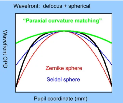
(11)A schematic comparison of the different quadric methods described here for the determination of the objective wavefront refraction for a given pupil size is depicted in Fig. 5.
Automatic Manifest Refraction Balance
These objective methods for calculating the refraction are optically correct but have some practical limitations in clinical practice20,21.
The devices to obtain the wavefront aberration of an eye use to work in the infrared range (IR), which is invisible for the human eye and avoid undesired miotic effects in the pupil
Fig. 4. Representation of the axial refractive error. The line of sight represents a chief ray; the wavefront aberration is zero at the pupil centre, and perpendicular to the line of sight. Each point of the wavefront propagates perpendicular to the local surface of the wavefront. The axial distance from the pupil centre to the intercept between the propagated local wavefront and the line of sight expressed in dioptres corresponds to the axial refractive error17.
Fig. 5. Comparison of the different quadric methods described here for the determination of the objective wavefront refraction for a given pupil size.
size. The refractive indices of the different optical elements in our visual system depend on the wavelength of the illumination light. In this way, the propagated wavefront (and the corresponding wavefront aberration) ingoing to (or outcoming from) our visual system depends on the wavelength of the illumination light, leading to the so-called chromatic aberration22.
The different methods provide “slightly” different results, depending on how they are compared to the subjective manifest refraction, one or another correlates better with manifest refraction16.
HOAb influence LOAb (refraction) when analysed for smaller diameters: For full pupil (e.g. 6 mm) the eye sees the world through HOAb producing some multifocality but without defocus, for a smaller pupil (e.g. 4 mm), the optical aberration of the eye is the same but the outer ring is blocked, thereby the eye sees the world through the central part of the HOAb, which may produce some defocus or astigmatism (LOAb, refraction).
A variation of the objective wavefront refraction from low-order Zernike modes at a fixed subpupil diameter of 4 mm was chosen as starting point to objectively include the measured subjective manifest refraction in the wave aberration (Fig. 6 to Fig. 9).
Fig. 6. Zernike refraction of a pure Spherical Aberration (at 6 mm) is per definition 0 because Spherical Aberration is a High Order Aberration mode, when analysed for a smaller diameter (4 mm) produces Defocus.
Fig. 7. Zernike refraction of a pure High Order Astigmatism (at 6 mm) is per definition 0 because of High Order Aberration mode, when analysed for a smaller diameter (4 mm) produces Astigmatism.
Fig. 8. Zernike refraction of a pure Coma (at 6 mm) is per definition 0 because Coma is a High Order Aberration mode, when analysed for a smaller diameter (4 mm) produces only tilt. Notice that coma may have “visual effect” if the visual axis changes producing
Astigmatism.
Fig. 9. Zernike refraction of a general wavefront aberration analysed at 6 mm and analysed for a smaller diameter (4 mm).
The expected optical impact of high-order aberrations in the refraction is calculated and modified from the input manifest refraction. The same wave aberration is analysed for two different diameters: for the full wavefront area (6 mm in this study) and for a fixed subpupil diameter of 4 mm. The difference in refraction obtained for each of the two diameters corresponds to the manifest refraction associated to the high-order aberrations (Fig. 10).
The condition is to re-obtain the input manifest refraction for the subpupil diameter of 4 mm. This way, the low-order parabolic terms of the modified wave aberration for the full wavefront area can be determined.
Comprehensive astigmatism planning and analysis
Step 1. (Common) Calculation of the correction at the corneal plane
We first recalculate the correction components from the spectacle plane to the corneal plane where the ablation will take place:
1
SP CP SPS
S
S VD
(12)Where SCP is the spherical component at corneal plane, SSP is the spherical component at
Fig. 10. Automatic Refraction Balance. Optical impact of the HOAb the refraction is calculated and balanced from input refraction. Notice that the same wavefront aberration is analysed for two different diameters. The difference in the refraction provided at the two different analysis diameters correspond to the manifest refraction provided by the high order aberration.
Refractive effect for 1 µm of aberration coefficient
-1.5 -1.0 -0.5 0.0 0.5 1.0 1.5 0.0 0.2 0.4 0.6 0.8 1.0 1.2
Scaling factor (Refractive Zone / Analysis diameter)
E q u iv a le n t C [2 ,m ] (µ m ) 2nd order 4th order 6th order 8th order
Fig. 11. Refractive effect of 1µm aberration as a function of the scaling factor from the analysis diameter to the considered refractive zone.
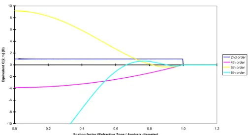
-10 -8 -6 -4 -2 0 2 0.0 0.2 0.4 0.6 0.8 1.0 1.2
Scaling factor (Refractive Zone / Analysis diameter)
Eq u iv a le n t C [2 ,m ] (D ) 2nd order 4th order 6th order 8th order
Fig. 12. Refractive effect of 1D aberration as a function of the scaling factor from the analysis diameter to the considered refractive zone.
1
SP SP CP CP SP SPS
C
C
S
S
C
VD
(13)Where CCP is the cylindrical component at corneal plane, and CSP is the cylindrical
component at spectacle plane.
Step 2. (Common) Correction of the corneal keratometries to anterior corneal surface curvatures
We measured the best-fit keratometry readings (K-readings) of Maloney index.
The different refractive indices used for the topography and the ablation planning (keratometric refractive index 1.3375 for the topographies, and corneal refractive index 1.376 for the ablations) were taken into account.
, Cornea Air ACS i i Topo Air
n
n
K
K
n
n
(14)Where KACS,i are the meridional corneal curvatures of the anterior corneal surface, Ki are the
Maloney K-readings of the cornea, nCornea is the refractive index of the cornea (1.376), nTopo is
the refractive index used by the topographer (1.3375), and nAir is the refractive index of the
air (1). ,
0.376
0.3375
ACS i iK
K
(15)Thus, a topographical condition e.g. of 41.65 D at 111°, and 41.21 D at 21°, is considered as 46.40 D at 111°, and 45.91 D at 21° anterior corneal surface curvature, due to the different
refractive indices used by the topographer (keratometric refractive index 1.3375) and the actual refractive index of the cornea (1.376).
Step 3. (Common) Expressing the correction at the corneal plane in power vector notation The conventional refractions in terms of sphere, cylinder and axis in minus-cylinder or plus-cylinder formats used by clinicians can be easily converted to a sphero-cylindrical prescription in power vector notation of the form [J0, M, J45].
The mathematical formulation is:
2
CP MR CPC
M
S
(16)
0,cos 2
2
CP MR MRC
J
A
(17)
45,sin 2
2
CP MR MRC
J
A
(18)Where M is the spherical equivalent of the manifest refraction at corneal plane, J0 the
cardinal astigmatism and J45 the oblique astigmatism. The components J0, M, and J45,
respectively, represent the power of a Jackson crossed-cylinder with axes at 0 and 90°, the spherical equivalent power, and the power of a Jackson crossed-cylinder with axes at 45 and 135°.
Step 4. (Common) Expressing the corneal curvatures in power vector notation
The conventional corneal curvatures used by clinicians can be easily converted to sphero-cylindrical corneal curvatures in power vector notation of the form [J0, M, J45].
The mathematical formulation is:
1 2
2
KK
K
M
(19)
1
2 1 2 0,cos 2
cos 2
2
2
KA
A
K
K
J
(20)
1
2 1 2 45,sin 2
sin 2
2
2
KA
A
K
K
J
(21)Where M is the spherical equivalent of the corneal curvatures, J0 the cardinal astigmatism
and J45 the oblique astigmatism.
Step 5. (Common) Calculation of the internal astigmatism in power vector notation
The internal astigmatism is the difference between the manifest and the corneal astigmatism.
The mathematical formulation is:
0,I 0,MR 0,K
J
J
J
(22)45,I 45,MR 45,K
45, 0,
arctan
2
I I IJ
J
A
(25)Step 7. (Common) Calculation of the predicted residual manifest refraction in power vector notation
The predicted residual manifest astigmatism is the difference between the planned and the manifest astigmatism.
The mathematical formulation is:
0,RM 0,MR 0,P
J J J (26)
45,RM 45,MR 45,P
J
J
J
(27)Step 8. (Common) Calculation of the predicted residual manifest refraction in clinician notation
The power vector notation is a cross-cylinder convention that is easily transposed into conventional refractions in terms of cylinder and axis in minus-cylinder or plus-cylinder formats used by clinicians.
, ,
2
RM CP RM CP RMC
S
M
(28) 2 2 ,2
0, 45, RM CP RM RMC
J
J
(29) 45, 0,arctan
2
RM RM RMJ
J
A
(30)Step 9. (Common) Expressing the predicted residual manifest refraction in clinician notation at spectacle plane
We then recalculate the correction components from the corneal plane to the spectacle plane:
, , , 1 RM CP RM SP RM CP S S S VD (31)
, ,
, , , ,1
RM CP RM CP RM SP RM SP RM CP RM CPS
C
C
S
S
C
VD
(32)Step 10. (Common) Calculation of the predicted residual corneal astigmatism in power vector notation
The predicted residual corneal astigmatism is the difference between the planned and the corneal astigmatism.
The mathematical formulation is:
0,RK 0,K 0,P
J
J
J
(33)45,RK 45,K 45,P
J
J
J
(34)Step 11. (Common) Calculation of the predicted residual corneal astigmatism in clinician notation
The power vector notation is a cross-cylinder convention that is easily transposed into conventional refractions in terms of cylinder and axis in minus-cylinder or plus-cylinder formats used by clinicians.
2 2 0, 45,
2
RK RK RKC
J
J
(35) 45, 0,arctan
2
RK RK RKJ
J
A
(36)Step 12. (Common) Expressing the predicted residual corneal astigmatism to keratometric astigmatism
The mathematical formulation is:
Topo Air RT RK Cornea Air
n
n
C
C
n
n
(37)Step 13. Possible scenarios for planning the astigmatic correction We have developed 5 methods to combine the information:
a. Plan to correct the manifest astigmatism (nothing from topography)
b. Plan to correct the corneal astigmatism (all from topography)
c. Plan to correct a combination of manifest and corneal astigmatism, minimizing the
residual global astigmatism magnitude (half the way between manifest and topographical astigmatism)
d. Plan to correct a combination of manifest and corneal astigmatism, minimizing the
magnitude of the corrected astigmatism (as much as possible from topography and manifest astigmatism without overcorrecting any of them)
e. Plan to correct a combination of manifest and corneal astigmatism, priorizing
with-the-rule corneal astigmatism
0,P 0,MR
J
J
(39)45,P 45,MR
J
J
(40)b. Plan to correct the corneal astigmatism
To correct the corneal astigmatism represents considering only the topographical astigmatism.
The mathematical formulation is:
P K
M
M
(41) 0,P 0,KJ
J
(42) 45,P 45,KJ
J
(43)c. Plan to minimize the residual global astigmatism magnitude
To correct a combination of manifest and corneal astigmatism, minimizing the residual global astigmatism magnitude represents in mathematical formulation:
2 2 Global RM RK
C
C
C
(44) 2 2 2 2 0, 45, 0, 45, 2 Global RM RM RK RK C J J J J (45)
2
2
2
2 0, 0, 45, 45, 0, 0, 45, 45,2
Global MR P MR P K P K PC
J
J
J
J
J
J
J
J
(46)We should find which plan minimizes the global cylinder: The mathematical formulation is:
P MR
M
M
(47) 0, 0, 0,2
MR K PJ
J
J
(48) 45, 45, 45,2
MR K PJ
J
J
(49)d. Plan to minimize the risk of overcorrecting any of the astigmatisms
To correct a combination of manifest and corneal astigmatism, minimizing the magnitude of the corrected astigmatism, as much as possible from topography and manifest astigmatism without overcorrecting any of them, represents in mathematical formulation:
P MR
M
M
(50)
0, 0, 0, 0, 0, 0, 0, 0, 0,0,
0
max
,
0,
0
min
,
0
MR K MR K P MR K MR KJ
J
J
J
J
J
J
J
J
otherwise
(51)
45, 45, 45, 45, 45, 45, 45, 45, 45,0,
0
max
,
0,
0
min
,
0
MR K MR K P MR K MR KJ
J
J
J
J
J
J
J
J
otherwise
(52)e. Plan to priorize with-the-rule corneal astigmatism
To correct a combination of manifest and corneal astigmatism, priorizing with-the-rule corneal astigmatism, represents in mathematical formulation:
P MR
M
M
(53)
0, 0, 0, 0, 0, 0, 0, 0, 0,0,
0
max
,
0,
0
min
,
0
MR K MR K P MR K MR KJ
J
J
J
J
J
J
J
J
otherwise
(54) 45, 45, 45,2
MR K PJ
J
J
(55)Step 14. (Common) Expressing the ablation plan in clinician notation
The power vector notation is a cross-cylinder convention that is easily transposed into conventional refractions in terms of cylinder and axis in minus-cylinder or plus-cylinder formats used by clinicians.
, ,
2
P CP P CP PC
S
M
(56)Step 15. (Common) Expressing the ablation plan in clinician notation at spectacle plane We then recalculate the correction components from the corneal plane to the spectacle plane: , , ,
1
P CP P SP P CPS
S
S
VD
(59)
, ,
, , , ,1
P CP P CP P SP P SP P CP P CPS
C
C
S
S
C
VD
(60)The idea of corneal vs. manifest astigmatism is not new.
The difference is that the decision used to be a „all-in/no-go“ decision, either full manifest correction or full corneal astigmatism correction.
We have developed 5 methods to combine the information, from which 2 are the "most novel and interesting ones":
0. Plan to correct the manifest astigmatism (nothing from topography)
1. Plan to correct the corneal astigmatism (all from topography)
2. Plan to correct a combination of manifest and corneal astigmatism, minimizing the residual global astigmatism magnitude (half the way between manifest and topographical astigmatism)
3. Plan to correct a combination of manifest and corneal astigmatism, minimizing the magnitude of the corrected astigmatism (as much as possible from topography and manifest astigmatism without overcorrecting any of them)
4. Plan to correct a combination of manifest and corneal astigmatism, priorizing
with-the-rule corneal astigmatism
What would you do if a patient shows -1.50x170 corneal astigmatism but -1.50x10 manifest? There are quite a number of parameters to consider:
- Vertex distance
- Different refractive indices between topographers and cornea
- Astigmatism angle
- Neural compensation
- etc…
for instance, the patient is -3.50 -1.50x10 @ 12, and Maloney indices are 43.25x80 and 41.75x170.
At first sight, we are a an easy case with low astigmatisms.
Actually, the patient is -3.36 -1.36x10 @ corneal plane (-1.67 D manifest astigmatism), and Maloney are 48.18x80 and 46.51x170 (-1.67 D corneal astigmatism).
Planning the 5 scenarios:
0. Plan to correct the manifest astigmatism (-3.50 -1.50x10 @ 12)
1. Plan to correct the corneal astigmatism (-3.33 -1.85x170 @ 12)
2. Plan to correct a combination of manifest and corneal astigmatism, minimizing the
residual global astigmatism magnitude (-3.46 -1.57x179 @ 12)
3. Plan to correct a combination of manifest and corneal astigmatism, minimizing the
magnitude of the corrected astigmatism (-3.54 -1.41x0 @ 12)
4. Plan to correct a combination of manifest and corneal astigmatism, priorizing
with-the-rule corneal astigmatism (-3.54 -1.41x179 @ 12) Postoperative predicted refractions would be:
0. Plan to correct the manifest astigmatism (0)
1. Plan to correct the corneal astigmatism (+0.54 -1.08x53 @ 12)
2. Plan to correct a combination of manifest and corneal astigmatism, minimizing the
residual global astigmatism magnitude (+0.27 -0.54x53 @ 12)
3. Plan to correct a combination of manifest and corneal astigmatism, minimizing the
magnitude of the corrected astigmatism (+0.23 -0.46x45 @ 12)
4. Plan to correct a combination of manifest and corneal astigmatism, priorizing
with-the-rule corneal astigmatism (+0.26 -0.52x45 @ 12) And the predicted postop cornal astigmatism:
0. Plan to correct the manifest astigmatism (-0.97x143)
1. Plan to correct the corneal astigmatism (0)
2. Plan to correct a combination of manifest and corneal astigmatism, minimizing the
residual global astigmatism magnitude (-0.48x143)
3. Plan to correct a combination of manifest and corneal astigmatism, minimizing the
magnitude of the corrected astigmatism (-0.58x149)
4. Plan to correct a combination of manifest and corneal astigmatism, priorizing
with-the-rule corneal astigmatism (-0.53x150) We propose 5 justified scenarios:
0. Plan to correct the manifest astigmatism (because it best satisfies patients subjective
feeling)
1. Plan to correct the corneal astigmatism (because the correction is directly onto the
cornea applied)
2. Plan to correct a combination of manifest and corneal astigmatism, minimizing the
residual global astigmatism magnitude (because the global residual astigmatism is thereby minimised)
3. Plan to correct a combination of manifest and corneal astigmatism, minimizing the
magnitude of the corrected astigmatism (because less corrected astigmatism means less tissue removed)
4. Plan to correct a combination of manifest and corneal astigmatism, priorizing
with-the-rule corneal astigmatism (because statistically with-the-with-the-rule corneal astigmatism is dominant
5. Centration of refractive profiles
Not to forget the fact that astigmatism (especially high ones) has its main origin in the anterior corneal surface, and topographically is usually found located 2-fold symmetrically
vertex (CV) measured by videokeratoscopy25 as the morphologic reference to centre corneal
refractive procedures.
Mainly, two different centration references that can be detected easily and measured with currently available technologies. PC may be the most extensively used centration method for several reasons. First, the pupil boundaries are the standard references observed by the eye-tracking devices. Moreover, the entrance pupil can be well represented by a circular or oval aperture, and these are the most common ablation areas. Centering on the pupil offers the opportunity to minimize the optical zone size. Because in LASIK there is a limited ablation area of about 9.25 mm (flap cap), the maximum allowable optical zone will be about 7.75 mm. Because laser ablation is a destructive tissue technique, and the amount of tissue
removed is directly related to the ablation area diameter,26 the ablation diameter, maximum
ablation depth, and ablation volume should be minimized. The planned optical zone should be the same size or slightly larger as the functional entrance pupil for the patients’ requirements.
The pupil centre considered for a patient who fixates properly defines the line-of-sight, which is the reference axis recommended by the OSA for representing the wavefront aberration27.
The main HOA effects (main parts of coma and spherical aberrations) arise from edge effects, i.e., strong local curvature changes from the optical zone to the transition zone and from the transition zone to the untreated cornea. It then is necessary to emphasize the use of a large optical zone (6.50 millimeter or more) to cover the scotopic pupil size, and a large and smooth transition zone.
Nevertheless, because the pupil centre is unstable, a morphologic reference is more advisable28,29,30. It is well known that the pupil centre shifts with changes in the pupil size47,
moreover, because the entrance pupil we see is a virtual image of the real one.
The CV in different modalities is the other major choice as the centration reference. In perfectly acquired topography, if the human optical system were truly coaxial, the corneal vertex would represent the corneal intercept of the optical axis. Despite the fact that the human optical system is not truly coaxial, the cornea is the main refractive surface. Thus, the corneal vertex represents a stable preferable morphologic reference. However, there are several ways to determine the corneal vertex: the most extensively used one is to determine
the coaxial corneal light reflex (1st Purkinje image). Nevertheless, as de Ortueta and Arba
Mosquera24 pointed out, there is a problem using the coaxial light reflex because surgeons
differ; for instance, the coaxial light reflex will be seen differently depending on surgeon eye dominance, surgeon eye balance, or the stereopsis angle of the microscope. For example, the LadarVision platform (Alcon) uses a coaxial photograph as reference to determine the
coaxial light reflex31, which is independent of the surgeons’ focus. Ablations can be centered
If an optical zone equivalent to the maximum pupil size (scotopic pupil size or dim mesopic) is applied on the corneal vertex, due to the offset, the ablation will not cover the full pupil area and it will be cut across it. As the pupil aperture represents the only area capable of collecting light, then the full pupil should be cover and an “oversized” OZ centered on the vertex shall be selected as:
2
ScoOZ
Pupil
OffSet
AETAcc
(61) However, centering in the pupil with a right selected OZ is not an easy task. We know thatthe pupil centre shifts versus pupil size changes; moreover as the pupil we see (entrance pupil) is a virtual image of the real one.
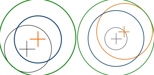
Fig. 13. Left: The black cross indicates the pupil centre and the black circle the maximum
pupil boundaries, whereas the orange cross represents the corneal apex. Pay attention that if we apply on the corneal apex an optical zone equivalent to the maximum pupil size
(scotopic pupil size or dim mesopic) (blue circle), due to the offset, the ablation will not cover the full pupil area and it will be cut across it. As the pupil aperture represents the only area capable of collecting light, then the full pupil should be cover and an “oversized” OZ
centred on the apex shall be selected (green circle). Right: Only centring in the scotopic
pupil (orange circle and cross) offers the opportunity to minimise the Optical Zone size (OZ), but under the laser pupil size is likely in a photopic state rather than dim mesopic one. Therefore, centring in the laser pupil an optical zone equivalent to the maximum pupil size (scotopic pupil size or dim mesopic) will induce edge effects.
Considering this, for aspherical, or, in general, non-wavefront-guided treatments, in which the minimum patient data set (sphere, cylinder, and axis values) from the diagnosis is used, it is assumed that the patient’s optical system is aberration-free or that those aberrations are not clinically relevant (otherwise a wavefront-guided treatment would have been planned). For those reasons, the most appropriate centering reference is the corneal vertex; modifying the corneal asphericity with an ablation profile neutral for aberrations, including loss of efficiency compensations.
Fig. 14. Comparison of topographical findings after centration at the pupil centre and corneal vertex, respectively. Notice the more symmetric topography after CV centration. For wavefront-guided treatments, change in aberrations according to diagnosis measurements, a more comprehensive data set from the patient diagnosis is used, including the aberrations, because the aberrations maps are described for a reference system in the centre of the entrance pupil. The most appropriate centering reference is the entrance pupil as measured in the diagnosis27.
Providing different centering references for different types of treatments is not ideal, because it is difficult to standardize the procedures. Nevertheless, ray tracing indicates that the optical axis is the ideal centering reference. Because this is difficult to standardize and considering that, the anterior corneal surface is the main refractive element of the human eye, the CV, defined as the point of maximum elevation, will be the closest reference. It shall be, however, noticed that on the less prevalent oblate corneas the point of maximum curvature (corneal apex) might be off centre and not represented by the corneal vertex. However, it would be interesting to refer the corneal and/or ocular wavefront measurements to the optical axis or the CV. This can be done easily for corneal wavefront analysis, because there is no limitation imposed by the pupil boundaries. However, it is not as easy for ocular wavefront analysis, because the portion of the cornea above the entrance pupil alone is responsible for the foveal vision. Moreover, in patients with corneal problems such as keratoconus/keratectasia, post-LASIK (pupil-centered), corneal warpage induced by contact lens wearing and other diseases causing irregularity on anterior corneal surface, the corneal vertex and the corneal apex may shift. In those cases, pupil centre is probably more stable. Moreover, since most laser systems are designed to perform multiple procedures besides LASIK, it is more beneficial that excimer laser systems have the flexibility to choose different centration strategies.
Due to the smaller angle kappa associated with myopes compared with hyperopes32,33,
large to show differences in results, because it is always desirable to achieve as much standardization as possible and not to treat the myopes using one reference, whereas the hyperopes use a different one.
The use of large optical zones may be responsible for the lack of difference in postoperative visual outcomes using two different centrations. However, hyperopic LASIK provides smaller functional optical zones and, for this reason, special caution shall be paid to these patients34.
Previous studies have reported that based on theoretical calculations with 7.0-mm pupils even for customized refractive surgery, that are much more sensitive to centration errors, it appears unlikely that optical quality would be degraded if the lateral alignment error did
not exceed 0.45 mm37. In 90% of eyes, even accuracy of 0.8 mm or better would have been
sufficient to achieve the goal37.
A pupillary offset of 0.25 millimeters seems to be sufficiently large to be responsible for
differences in ocular aberrations28, however, not large enough to correlate this difference in
ocular aberrations with functional vision.
Centering on the pupil offers the opportunity to minimize the optical zone size, whereas centering in the CV offers the opportunity to use a stable morphologic axis and to maintain the corneal morphology after treatment.
6. Eye-tracking
The Cyclotorsion ProblemThe analysis of cyclotorsion movements have been made since the middle of the 20th
century. Several papers demonstrate some dynamic compensatory movement to keep the image at the retina aligned to a natural orientation, whereas some suggestions have been
made on significant cyclotorsion occurring under monocular viewing conditions35.
Measuring rotation when the patient is upright36 to when the refractive treatments are
performed with the patient supine may lead to ocular cyclotorsion, resulting in mismatching
of the applied versus the intended profiles37,38. Recently, some equipment can facilitate
measurement of and potential compensation for static cyclotorsion occurring when the
patient moves from upright to the supine position during the procedure39, quantifying the
cyclorotation occurring between wavefront measurement and laser refractive surgery40 and
compensating for it41,42,43.
Further measuring and compensating ocular cyclotorsion during refractive treatments with the patient supine may reduce optical noise of the applied versus the intended profiles44,45,46.
It usually happens that the pupil size and centre differ for the treatment compared to that
during diagnosis.47 Then, excluding cyclotorsion, there is already a lateral displacement that
mismatches the ablation profile. Further, cyclotorsion occurring around any position other than the ablation centre results in additional lateral displacement combined with cyclotorsion.48
Many studies, in the last times have worked out in an excellent way, the methodologies and implications of ocular cyclotorsion, but due to inherent technical problems, not many papers pay attention to the repeatability and reproducibility of the measurements.
Arba Mosquera et al.38 obtained an average cyclotorsional error of 4.39°, which agrees with
results reported in refractive surgery.
Considering that the average cyclotorsion resulting from the shift from the upright to the
supine position is about ±4°,49 without an aid other than manual orientation, confirms why
spherocylindrical corrections in laser refractive surgery have succeeded.
With currently available eye registration technologies, which provide an accuracy of about ±1.5°, opens a new era in corneal laser refractive surgery, because patients may be treated for a wider range of refractive problems with enhanced success ratios. However, this requires a higher resolution than technically achievable with currently available systems.52,53
Bueeler and co-authors54 determined conditions and tolerances for cyclotorsional accuracy.
Their OT criterion represents an optical benefit condition, and their results for the tolerance limits (29° for 3-mm pupils and 21° for 7-mm pupils) did not differ greatly from the optical
benefit result for astigmatism by Arba Mosquera et al.,38 confirming that astigmatism is the
major component to be considered.
Cyclotorsional errors result in residual aberrations and with increasing cyclotorsional error there is a greater potential for inducing aberrations. Eyes having over 10° of calculated cyclotorsion, predict approximately a 35% residual astigmatic error. Because astigmatic error is generally the highest magnitude vectorial aberration, patients with higher levels of astigmatism are at higher risk of problems due to cyclotorsional error.
Ocular cyclotorsion during laser refractive surgery may lead to significant decrease in the refractive outcomes due to inadequate correction or induction of astigmatism and higher
order aberrations1. During normal activities, human eyes can undergo significant torsional
movements of up to 15 degrees of the resting position depending on the motion and
orientation of the patient’s head and body2. In particular, there can be a significant degree of
cyclotorsion, particularly with monocular viewing conditions, between the seated and
supine positions ranging from 0- 16˚ in published studies1-5. This type of cyclotorsion that
occurs when the patient moves from the upright to the supine position is known as static cyclotorsion and can lead to significant unwanted outcomes during refractive laser ablations
of astigmatic eyes. Theoretical analyses show that a 4˚ misalignment can lead to a 14%
under-treatment of astigmatism, 6˚ to 20% under-correction and 16˚ to a 50%
under-correction1.
Cyclotorsion control may be of 2 types: i) dynamic cyclotorsion controls that allows
compensation for torsional eye movements during the laser treatments and ii) static
cyclotorsion control that allows compensation for torsional differences in eye positions between the patient being in an upright (during diagnosis) and supine position (during surgery). Currently, new installed excimer lasers have the ability to compensate for cyclotorsion, but most of the excimer lasers in use do not have such ability.
Calculation of the static cyclotorsion is based on comparisons of the corneal wavefront image obtained from the Keratron-Scout videokeratoscope [Optikon 2000 S.p.A, Italy] from
the patient in the upright position and the image taken from the SCHWIND AMARIS laser camera with the patient in the supine position. The laser computer algorithm searches for important landmarks starting at the borderline of the pupil and moving outwards until the image is completely scanned or the number of the prerequisite important points is reached. The software algorithm scans both the iris and the sclera. Mostly the rainbow shape of the iris with the vessels in the sclera provides enough information to register the cyclotorsion and no preoperative marking of the eye is necessary. In the case of a photopic pupil size, the iris delivers more reliable data. However, if the pupil is of scotopic size and the iris is reduced to a thin ring, the structures at the sclera can be detected and used to improve the robustness of the search. Before the treatment starts the advanced cyclotorsion control algorithm of the laser compares the 2 images, superimposes the important landmarks and calculates the angle of rotation. The laser software automatically corrects for the dynamic cyclotorsion. However, the surgeon has the possibility to ask for static cyclotorsion compensation or not, with a range of compensation of +/- 15°. Accuracy of cyclotorsion compensation is increased by the fact that algorithm used by the SCHWIND AMARIS does not rotate the complete volume of ablation but rather compensates each pulse individually for the cyclotorsion.
treatment of astigmatism. Thus we can conclude that the software is able to accurately lock on to eye position and compensate for the static cyclotorsion. This significant improvement in astigmatic and refractive outcomes in the SCC group is translated into improved safety. Noteworthy the magnitude and distribution of uncompensated cyclotorsion in former patients treated without SCC is similar to the magnitude and distribution of compensated cyclotorsion in the SCC. The importance of compensation of even small amounts of cyclotorsion would be expected to be even more important in wavefront guided treatments where it has been calculated that to achieve the diffraction limit in 95% of measured normal eyes with a 7.0 mm pupil, alignment of wavefront guided treatment would require a torsional precision of 1 degree or better11.
Not all lasers have specific software and/or hardware to actively compensate for positional cyclotorsion, and some achieve excellent results through alternative approaches. For example, Wavelight lasers achieve excellent outcomes for treatment of astigmatism. This is most likely due to the use of a lighting system which provides an "artificial horizon" which the patient sees when in the supine position under the laser.
The good thing of the SCC with CW is that the same image for topographical analysis is used for CW analysis and for SCC as well (as opposed to OW in which the H-S image is used for OW and another image, simultaneous or not, is used for SCC). The corneal wavefront image and the iris and sclera images are the same, so no mapping is needed. The Keratron keratoscope obtains information about the iris and sclera.
Uncompensated cyclotorsion errors in the SCC group can be attributed to: resolution and accuracy of the diagnosis image, resolution and accuracy of the laser image, possible misalignment of the scanner to the ET camera, possible misalignment of the manifest astigmatism to the topography, etc…
Ocular cyclotorsion during laser refractive surgery may lead to significant decrease in the refractive outcomes due to inadequate correction or induction of astigmatism and higher order aberrations, if astigmatism and higher order aberrations are present AND ONLY IF astigmatism and higher order aberrations are attempted to be corrected.
7. Other concerns
Tissue saving concernsThe real impact of tissue saving algorithms in customized treatments is still discussed in a controversial way. The problem of minimizing the amount of tissue is that it must be done in such a way that:
a. does not compromise the refractive correction55,56,57,58,59
b. does not compromise the visual performance
Distribution of the compensated cyclotorsion 0 5 10 15 20 25 30 35
<1deg 1deg to 3deg 3deg to 5deg 5deg to 8deg 8deg to 10deg
Compensated cyclotorsion (deg)
N u m b e r o f tr e a tm e n ts with SCC
Distribution of the uncompensated cyclotorsion error
0 5 10 15 20 25 30 35
<1deg 1deg to 3deg 3deg to 5deg 5deg to 8deg 8deg to 10deg
Uncompensated cyclotorsion error (deg)
N u m b e r o f tr e a tm e n ts with SCC w/o SCC
Fig. 16. Comparison of compensated (top) and uncompensated (bottom) torsional errors. Notice the similarities of the distribution of the compensated torsion when using SCC and of the uncompensated torsion when not using SCC. Notice as well, the much tighter
distribution around smaller residual torsional errors for the uncompensated torsion when using SCC.
According to this classification, Zernike terms can be considered not clinically relevant if their associated optical blur is lower than < 0.25 D, Zernike terms that might be considered clinically relevant correspond to optical blur values between 0.25 D and 0.50 D, and Zernike terms considered clinically relevant have associated optical blur values larger than 0.50 D. There are different proposed approaches for minimizing tissue ablation in refractive surgery:
In the multizonal treatments61, the minimization is based on the concept of progressive
decreasing corrections in different optical zones. The problem comes from the induced aberrations (especially spherical aberration).
In the treatments planned with smaller optical zone62 combined with bigger transition
zones, the minimization is a variation of the multizone concept. The problem comes, as well, from the induced aberrations (especially spherical aberration).
In the treatments planned with smaller optical zone for the cylindrical component63 (in
general for the most powerful correction axis), the minimization is based upon the concept of the maximal depth being based on the lowest meridional refraction and the selected optical zone, and the effective optical zone of the highest meridional refraction is reduced to match the same maximal depth. The problem comes from the induced aberrations (especially high order astigmatism).
In the boost slider method, minimization is produced by linear modulation of the ablated volume. The problem comes from induced changes in refraction produced by modulation.
In the Z-clip method64, minimization consists of defining a “saturation depth” for the
ablated volume, all points planned to ablate deeper than the saturation value are ablated only by an amount equal to the saturation value. The problem is that this “saturation limit” may occur anywhere in the ablation volume, compromising the refraction when they occur close to the ablation centre, and affecting the induction of aberrations in a complicated way.
In the Z-shift method64, minimization consists of defining a “threshold value” for the
ablated volume, no points planned to ablate less than the threshold value are ablated, and the rest of the points are ablated by an amount equal to the original planned ablation minus the threshold value. The problem comes from the fact that this “threshold value” may occur anywhere in the ablation volume, compromising the refraction when they occur close to the ablation centre, and the functional optical zone when occurring at the periphery.
Other minimization approaches65 consist of simplifying the profile by selecting a subset of
Zernike terms that minimizes the necessary ablation depth of ablation volume but respecting the Zernike terms considered as clinically relevant.
For each combination subset of Zernike terms, the low order terms are recalculated in a way that it does not compromise the refractive correction. Considering that the Zernike terms are either planned to be corrected or left, it does not compromise the visual performance because all left (not planned to correct) terms are below clinical relevance. The proposed approaches are safe, reliable and reproducible due to the objective foundation upon which they are based. In the same way, the selected optical zone will be used for the correction.
It is important to remark; the selection of the Zernike terms to be included in the correction is not trivial. Only Zernike terms considered not clinically relevant or minor clinically relevant can be excluded from the correction, but they must not be necessarily excluded. Actually, single Zernike terms considered not clinically relevant will only be disabled when they represent an extra tissue for the ablation, and will be enabled when they help to save tissue for the ablation.
In this way, particular cases are represented by the full wavefront correction, by disabling all not clinically relevant terms, or by disabling all high order terms.
The selection process is completely automatically driven by a computer, ensuring systematic results, and minimization of the amount of tissue to be ablated, simplifying the foreseeable problems of manually selecting the adequate set of terms.
Fig. 17. Optimised Aberration Modes Selection. Based on the wavefront aberration map, the software is able to recommend the best possible aberration modes selection to minimise tissue and time, without compromising the visual quality. Notice that the wavefront aberration is analysed by the software showing the original ablation for a full wavefront correction and the suggested set of aberration modes to be corrected. Notice the difference in required tissue, but notice as well that the most representative characteristics of the wavefront map are still presented in the minimised tissue selection.