Ultrasonic clamp-on flowmeter
ER 3.4.0_
OPTISONIC 6300
OPTISONIC 6300
OPTISONIC 6300
1 Safety instructions
6
1.1 Software history ... 6
1.2 Intended use ... 6
1.3 Certification ... 6
1.4 Safety instructions from the manufacturer ... 8
1.4.1 Copyright and data protection ... 8
1.4.2 Disclaimer ... 8
1.4.3 Product liability and warranty ... 9
1.4.4 Information concerning the documentation... 9
1.4.5 Warnings and symbols used... 10
1.5 Safety instructions for the operator... 10
2 Device description
11
2.1 Scope of delivery... 11
2.2 Device description ... 12
2.3 Nameplates ... 13
2.3.1 Overview ... 13 2.3.2 Flow sensor... 13 2.3.3 Signal converter... 142.3.4 Electrical connection data of inputs/outputs (example of basic version)... 15
3 Installation
16
3.1 Notes on installation ... 16
3.2 Storage ... 16
3.3 Transport ... 16
3.4 Pre-installation requirements ... 16
3.4.1 Environmental requirements ... 163.4.2 Installation requirements signal converter ... 17
3.5 Installation requirements sensor ... 17
3.5.1 Inlet, outlet and recommended mounting area ... 18
3.5.2 Long horizontal pipes ... 18
3.5.3 Open feed or discharge... 19
3.5.4 Down going pipeline over 5 m /16 ft length... 19
3.5.5 Position of control valve... 19
3.5.6 Position of pump ... 20
3.5.7 Pipe diameters and sensor construction ... 20
3.5.8 Pipe and media parameters ... 20
3.6 Installation of the flowmeter... 21
3.6.1 General mechanical installation... 21
4.1 Safety instructions... 29
4.2 Construction of the various housing versions ... 29
4.2.1 UFC 300 F ... 29
4.2.2 UFC 300 W ... 30
4.3 Electrical connection... 31
4.3.1 Signal cable to flow sensor... 31
4.3.2 Signal cable and power supply signal converter... 33
4.3.3 Laying electrical cables correctly... 35
4.4 Description of the electrical symbols ... 36
4.5 Basic inputs and outputs... 37
4.5.1 Fixed, non-alterable input/output versions... 38
4.5.2 Basic inputs/outputs ... 40
4.5.3 HART® connection ... 43
4.6 Modular Inputs and Outputs... 44
4.6.1 Alterable input/output versions... 44
4.6.2 Modular inputs/outputs and bus systems ... 46
4.6.3 HART® connection ... 54
5 Start-up
56
5.1 General instructions for programming... 56
5.2 Start measurement of small / medium version ... 60
5.3 Start measurement of large version... 61
5.4 Mechanical installation for large version ... 63
6 Operation
73
6.1 Menu overview... 73
6.2 Menu structure ... 74
6.2.1 Quick setup... 74 6.2.2 Test... 76 6.2.3 Setup ... 78 6.2.4 Customize settings ... 857.7.2 Form (for copying) to accompany a returned device... 105
7.8 Disposal ... 105
8 Technical data
106
8.1 Measuring principle... 106
8.2 Technical data... 107
8.3 Dimensions and weights ... 115
8.3.1 Housing ... 115
8.3.2 Clamp-on sensor and cable box ... 116
8.3.3 Mounting plate, field housing ... 118
8.3.4 Mounting plate, wall-mounted housing ... 118
1
SAFETY INSTRUCTIONS
OPTISONIC 63001.1 Software history
For all GDC devices, the "Electronic Revision" (ER) is consulted to document the revision status of the electronics according to NE 53. It is easy to see from the ER whether any fault repairs or major changes to the electronic equipment have taken place and what effect they have had on compatibility.
Changes and effect on compatibility
1.2 Intended use
1 Downwards compatible changes and fault repair with no effect on operation (e.g. spelling mistakes on display)
2-_ Downwards compatible hardware and/or software change of interfaces: H HART®
P PROFIBUS
F Foundation Fieldbus M Modbus
X all interfaces
3-_ Downwards compatible hardware and/or software change of inputs and outputs: I Current output
F, P Frequency / pulse output S Status output
C Control input CI Current input X all inputs and outputs
4 Downwards compatible changes with new functions
5 Incompatible changes, i.e. electronic equipment must be changed.
INFORMATION!
In the table below, "x" is a placeholder for possible multi-digit alphanumeric combinations,
depending on the available version.
All devices are based on the CE marking and meet the requirements of NAMUR Guideline NE 21 / 04.
DANGER!
For devices used in hazardous areas, additional safety notes apply; please refer to the Ex
documentation.
1.4 Safety instructions from the manufacturer
1.4.1 Copyright and data protection
The contents of this document have been created with great care. Nevertheless, we provide no guarantee that the contents are correct, complete or up-to-date.
The contents and works in this document are subject to German copyright. Contributions from third parties are identified as such. Reproduction, processing, dissemination and any type of use beyond what is permitted under copyright requires written authorisation from the respective author and/or the manufacturer.
The manufacturer tries always to observe the copyrights of others, and to draw on works created in-house or works in the public domain.
The collection of personal data (such as names, street addresses or e-mail addresses) in the manufacturer's documents is always on a voluntary basis whenever possible. Whenever feasible, it is always possible to make use of the offerings and services without providing any personal data.
We draw your attention to the fact that data transmission over the Internet (e.g. when communicating by e-mail) may involve gaps in security. It is not possible to protect such data completely against access by third parties.
We hereby expressly prohibit the use of the contact data published as part of our duty to publish an imprint for the purpose of sending us any advertising or informational materials that we have not expressly requested.
1.4.2 Disclaimer
The manufacturer will not be liable for any damage of any kind by using its product, including, but not limited to direct, indirect, incidental, punitive and consequential damages.
This disclaimer does not apply in case the manufacturer has acted on purpose or with gross negligence. In the event any applicable law does not allow such limitations on implied warranties
1.4.3 Product liability and warranty
The operator shall bear responsibility for the suitability of the device for the specific purpose. The manufacturer accepts no liability for the consequences of misuse by the operator. Improper installation and operation of the devices (systems) will cause the warranty to be void. The respective "Standard Terms and Conditions" which form the basis for the sales contract shall also apply.
1.4.4 Information concerning the documentation
To prevent any injury to the user or damage to the device it is essential that you read the information in this document and observe applicable national standards, safety requirements and accident prevention regulations.
If this document is not in your native language and if you have any problems understanding the text, we advise you to contact your local office for assistance. The manufacturer can not accept responsibility for any damage or injury caused by misunderstanding of the information in this document.
This document is provided to help you establish operating conditions, which will permit safe and efficient use of this device. Special considerations and precautions are also described in the document, which appear in the form of underneath icons.
1.4.5 Warnings and symbols used
Safety warnings are indicated by the following symbols.
DANGER!
This information refers to the immediate danger when working with electricity.
DANGER!
This warning refers to the immediate danger of burns caused by heat or hot surfaces.
DANGER!
This warning refers to the immediate danger when using this device in a hazardous atmosphere.
DANGER!
These warnings must be observed without fail. Even partial disregard of this warning can lead to
serious health problems and even death. There is also the risk of seriously damaging the device
or parts of the operator's plant.
WARNING!
Disregarding this safety warning, even if only in part, poses the risk of serious health problems.
There is also the risk of damaging the device or parts of the operator's plant.
CAUTION!
Disregarding these instructions can result in damage to the device or to parts of the operator's
plant.
INFORMATION!
These instructions contain important information for the handling of the device.
LEGAL NOTICE!
DEVICE DESCRIPTION
2
OPTISONIC 63002.1 Scope of delivery
INFORMATION!
Check the packing list to check if you received completely all that you ordered.
INFORMATION!
Inspect the cartons carefully for damage or signs of rough handling. Report damage to the
carrier and to the local office of the manufacturer.
INFORMATION!
The device will arrive in two cartons. The square carton contains the converter. The rectangular
carton contains the transducer set.
Figure 2-1: Scope of delivery
1 Signal converter, wall version or field version 2 Quick Start
3 CD-ROM (including Handbook, Quick Start, Technical Datasheet, Support database, movie) 4 Factory calibration report
5 Sensor plus cover (stainless steel / XT version without cover) 6 Metal strap
7 Mineral coupling grease (standard versions) or high temperature contactgel Pyrogel® (XT versions) 8 Signal cable plus connector cap (XT versions have a protection sleeve around the signal cable).
2.2 Device description
The ultrasonic clamp-on flowmeter can be fitted on the outside of piping to measure the flow rate of liquids.
The device is a combination of one up to two clamp-on sensor(s) and one ultrasonic flow converter.
Additionally for large version:
1 2nd sensor plus cover
2 90 degree screw driver 3 4 fixing units
4 Positioning tool 5 2 metal straps
6 Signal cable plus connector cap 7 Cable box plus signal cable
INFORMATION!
The underneath accessories can be ordered optionally:
• GDC interface set• SoundCheck
• Coupling grease; mineral (standard versions)
• High temperature contact gel Pyrogel® (XT versions)
2.3 Nameplates
2.3.1 Overview
2.3.2 Flow sensor
INFORMATION!
Look at the device nameplate to ensure that the device is delivered according to your order.
Check for the correct supply voltage printed on the nameplate.
Figure 2-3: Visual check
1 Flow sensor 2 Signal converter
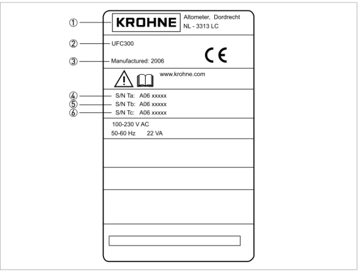
2.3.3 Signal converter
Figure 2-5: Nameplate
1 Manufacturer 2 Device type 3 Manufacturing year
4 Serial number sensor 1 + short code flow sensor 5 Serial number sensor 2 + short code flow sensor 6 Empty
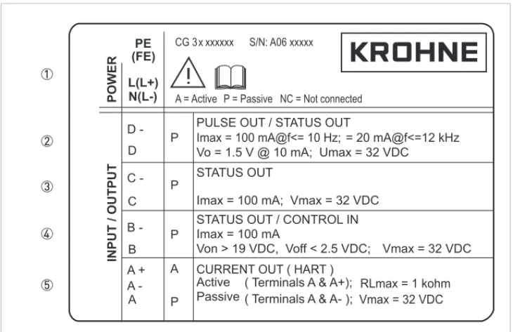
2.3.4 Electrical connection data of inputs/outputs (example of basic version)
• A = active mode; the signal converter supplies the power for connection of the subsequent devices
• P = passive mode; external power supply required for operation of the subsequent devices
• N/C = connection terminals not connected
Figure 2-6: Example of a nameplate for electrical connection data of inputs and outputs
1 Power supply (AC: L and N; DC: L+ and L-; PE for ≥ 24 VAC; FE for ≤ 24 VAC and DC) 2 Connection data of connection terminal
D/D-3 Connection data of connection terminal C/C-4 Connection data of connection terminal
3
INSTALLATION
OPTISONIC 63003.1 Notes on installation
3.2 Storage
• Store the flowmeter in a dry and dust-free location.
• Avoid lasting direct exposure to the sun.
• Store the flowmeter in its original packing.
3.3 Transport
No special requirements.
3.4 Pre-installation requirements
3.4.1 Environmental requirements
INFORMATION!
Inspect the cartons carefully for damage or signs of rough handling. Report damage to the
carrier and to the local office of the manufacturer.
INFORMATION!
Check the packing list to check if you received completely all that you ordered.
INFORMATION!
Look at the device nameplate to ensure that the device is delivered according to your order.
Check for the correct supply voltage printed on the nameplate.
INFORMATION!
To assure a quick, safe and uncomplicated installation, we kindly request you to make provisions
as stated below.
3.4.2 Installation requirements signal converter
• Allow 10…20 cm / 3.9…7.9" of space at the sides and rear of the signal converter to permit free air circulation.
• Protect signal converter against direct solar radiation, install a sunshield if necessary.
• Signal converters installed in switchgear cabinets require adequate cooling, e.g. by fan or heat exchanger.
• Do not expose the signal converter to intense vibration.
3.5 Installation requirements sensor
INFORMATION!
For detailed information please also refer to Housing on page 115.
INFORMATION!
To avoid measuring errors and malfunctioning of the flowmeter due to gas or air inclusions or an
empty pipe, please observe the following precautions.
CAUTION!
Since gas will collect at the highest point of a pipe, installation of the flowmeter at that location
should be avoided at all times. Also installation in a down going pipe should be avoided since a
completely filled pipe may not be guaranteed due to cascading effects. Additionally flow profile
distortion is possible.
CAUTION!
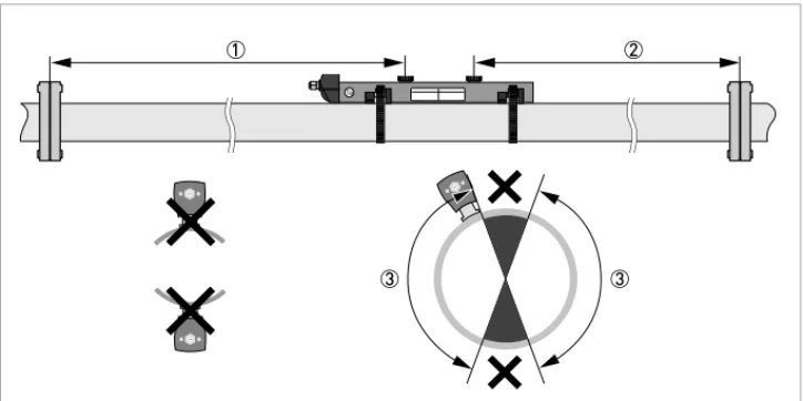
3.5.1 Inlet, outlet and recommended mounting area
3.5.2 Long horizontal pipes
• Install on slightly ascending pipe section.
• If not possible, ensure adequate velocity to prevent air, gas or vapor from collecting in upper part.
Figure 3-1: Inlet, outlet and recommended mounting area
1 Min. 10 DN 2 Min. 5 DN 3 OK, 120°
CAUTION!
Especially for XT (eXtended Temperature) versions:
•
Always install the sensor at a non-insulated part of the pipe. Remove any insulation if
necessary!
•
Bend radius of cable plus connection box needs 10 cm / 4" additional non insulated pipe
section.
3.5.3 Open feed or discharge
Install meter on a lowered section of the pipe to ensure a full pipe condition through the meter.
3.5.4 Down going pipeline over 5 m /16 ft length
Install air vent downstream of the flow meter to prevent vacuum. Although this will not harm the meter, it may cause gases to come out of solution (cavitate) and interfere with proper
measurements.
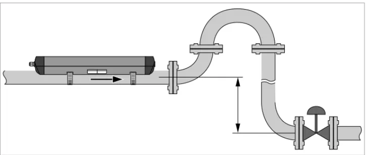
3.5.5 Position of control valve
Always install control valves downstream of flowmeter in order to avoid cavitation or distortion of flow profile.
Figure 3-3: Open feed or discharge
3.5.6 Position of pump
3.5.7 Pipe diameters and sensor construction
3.5.8 Pipe and media parameters
CAUTION!
Never install flowmeter at a pump suction side in order to avoid cavitation or flashing in the
flowmeter.
Figure 3-6: Position of pump
Figure 3-7: Measuring modes
1 Z-mode 2 V-mode 3 W-mode
INFORMATION!
3.6 Installation of the flowmeter
3.6.1 General mechanical installation
Installation of the rails with the metal straps Installation of the rails with the metal strapsInstallation of the rails with the metal straps Installation of the rails with the metal straps
Change the position of the transducer Change the position of the transducerChange the position of the transducer Change the position of the transducer
• Unlock the floating transducer 2 by turning the locking knob 1 counter clockwise.
• Slide the transducer 2 to the advised mounting distance3 (menu X9.4).
• Lock the transducer by turning the locking knob 1 clockwise. Greasing the transducer surfaces
Greasing the transducer surfacesGreasing the transducer surfaces Greasing the transducer surfaces
Mounting the cover Mounting the coverMounting the cover Mounting the cover
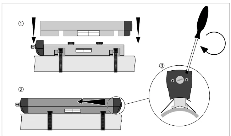
3.6.2 Installation instructions for small and medium version
INFORMATION!
Not applicable for stainless steel / XT versions. These are delivered without cover.
Figure 3-8: Procedure for installation of small or medium version
1 Rail, small version 2 Rail, medium version 3 Choose for V-mode or ... 4 Choose for W-mode 5 Make settings in converter
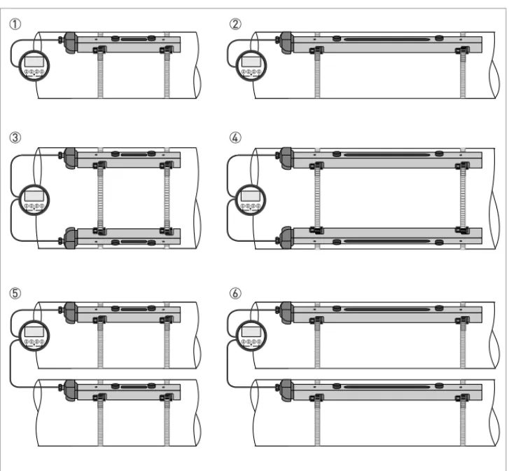
Figure 3-9: Device versions
1 Small version: single pipe / single path 2 Medium version: single pipe / single path 3 Small version: single pipe / dual path 4 Medium version: single pipe / dual path 5 Small version: dual pipe / single path 6 Medium version: dual pipe / single path
3.6.3 Installation instructions for large version
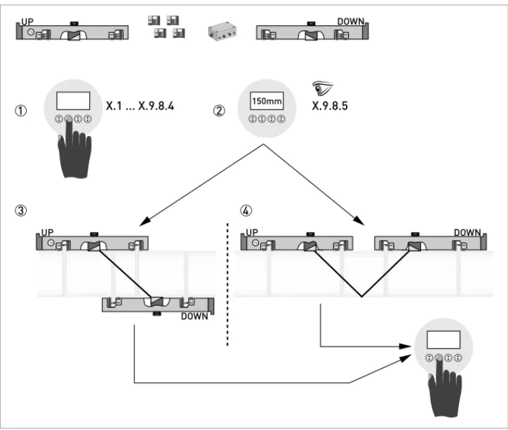
Figure 3-10: Procedure for installation of large version
1 Enter the values for the installation menu, X1...X9.8.4 2 Read the advised mounting distance in menu X9.8.5 3 Choose for Z-mode (default) or ...
4 Choose for V-mode 5 Finish the installation menu
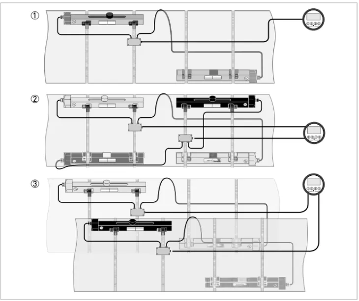
Figure 3-11: Device versions
1 Single pipe, single path 2 Single pipe, dual path 3 Dual pipe
3.7 Mounting of converter
3.7.1 Mounting of UFC 300 F
Perform the following procedures:
• Mount converter with mounting plate on wall or standpipe.
• Observe maximum allowed length of 30 m / 98.4 ft for the signal cable
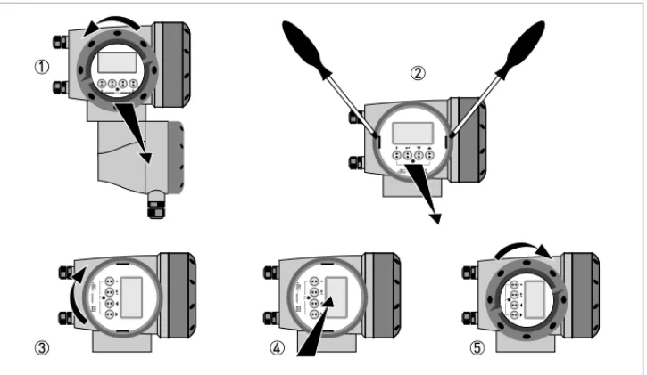
3.7.2 Turning the display of the field housing version
The display of the field housing version can be turned in 90° increments.
1 Unscrew the cover from the display and operation control unit.
2 Using a suitable tool, pull out the two metal puller devices to the left and right of the display. 3 Pull out the display between the two metal puller devices and rotate it to the required position. 4 Slide the display and then the metal puller devices back into the housing.
5 Re-fit the cover and tighten it by hand.
CAUTION!
Always use the supplied signal cable. Keep the distance between the sensor and the signal
converter as short as possible.
Figure 3-12: Turning the display of the field housing version
CAUTION!
3.7.3 Mounting of UFC 300 W
Perform the following procedures:
• Remove aluminium mounting plate from rear of the signal converter, and attach to wall or standpipe.
• Mount signal converter.
• Position lock washers and nuts on the housing bolts, tighten nuts slightly.
• Align housing, tighten nuts firmly.
ELECTRICAL CONNECTIONS
4
OPTISONIC 63004.1 Safety instructions
4.2 Construction of the various housing versions
4.2.1 UFC 300 F
The terminal compartments are accessible after unscrewing cover 2 and 6.
DANGER!
All work on the electrical connections may only be carried out with the power disconnected. Take
note of the voltage data on the nameplate!
DANGER!
Observe the national regulations for electrical installations!
DANGER!
For devices used in hazardous areas, additional safety notes apply; please refer to the Ex
documentation.
WARNING!
Observe without fail the local occupational health and safety regulations. Any work done on the
electrical components of the measuring device may only be carried out by properly trained
specialists.
INFORMATION!
Look at the device nameplate to ensure that the device is delivered according to your order.
Check for the correct supply voltage printed on the nameplate.
4.2.2 UFC 300 W
The terminal compartments are accessible after opening cover 2.
Figure 4-2: Construction of remote version
1 Cover, electronics compartment
2 Cover for the three separate terminal compartments for power, sensor connection and inputs/outputs 3 Locking screw, 1/2 turn left/right to open/close cover 2
4 Sensor terminal compartment
5 Terminal compartment for inputs/outputs
4.3 Electrical connection
The flow sensor is connected to the signal converter via the single signal cable.
4.3.1 Signal cable to flow sensor
CAUTION!
To ensure smooth functioning, always use the signal cables included in the delivery.
Figure 4-3: Connecting the signal cable to the rail (small and medium version)
1 Connect the green cable to "DOWN" 2 Connect the blue cable to "UP"
3 Turn the screws clockwise to secure the cap
Figure 4-4: Connect the signal cable in case of stainless steel / XT version.
1 Put in the connector.
2 Turn knob to secure the connector.
CAUTION!
For XT versions: check if the signal cable is heat protected with the protection sleeve of 1 meter /
40".
Figure 4-5: Connections in cable box (large version)
1 Connect the blue cable to the UP rail. 2 Connect the green cable to the DOWN rail. 3 Make connections in cable box.
4 Cable to converter
4.3.2 Signal cable and power supply signal converter
INFORMATION!
The power terminals in the terminal compartments are equipped with additional hinged lids to
prevent accidental contact.
DANGER!
The device must be grounded in accordance with regulations in order to protect personnel
against electric shocks.
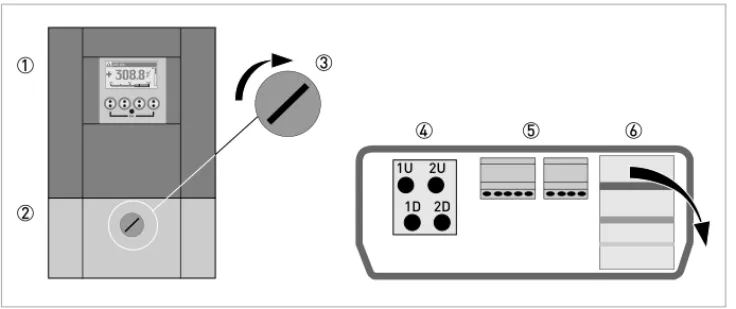
Figure 4-6: Construction of wall version
1 Connect blue cable to 1U (to 2U for 2nd sensor) and the green cable to 1D (2D for 2nd sensor) 2 Communication I/O
100…230 VAC (-15% / +10%)
• Connect the protective ground conductor PE of the mains power supply to the separate terminal in the terminal compartment of the signal converter.
• Connect the live conductor to the L terminal and the neutral conductor to the N terminal.
24 VAC/DC (-15% / +10%)
• For reasons to do with the measurement process, connect a functional ground FE to the separate U-clamp terminal in the terminal compartment of the signal converter.
• When connecting to functional extra-low voltages, provide a facility for protective separation (PELV) (VDE 0100 / VDE 0106 and/or IEC 364 / IEC 536 or relevant national regulations).
Figure 4-7: Construction (field version)
1 Cover, electronics compartment
2 Cover, terminal compartment for power supply and inputs/outputs 3 Cable entry for power
4 Cable entry for inputs/outputs 5 Cable entry for sensor cable 6 Cover, sensor terminal compartment
4.3.3 Laying electrical cables correctly
1 Lay the cable in a loop just before the housing.
2 Tighten the screw connection of the cable entry securely. 3 Never mount the housing with the cable entries facing upwards. 4 Seal cable entries that are not needed with a plug.
4.4 Description of the electrical symbols
mA meter0...20 mA or 4...20 mA and other
RL is the internal resistance of the measuring point including the cable resistance
DC voltage source (Uext), external power supply, any connection polarity
DC voltage source (Uext), observe connection polarity according to connection diagrams
Internal DC voltage source
Controlled internal power source in the device
Electronic or electromagnetic counter
At frequencies above 100 Hz, shielded cables must be used to connect the counters.
Ri Internal resistance of the counter
Button, NO contact or similar
4.5 Basic inputs and outputs
The signal converter has several in / output ports, accessible via the terminal compartment for interfacing with external devices. The terminal compartment is accessible after unscrewing the cover.
The input / output ports are galvanic separated from each other and from all other input and output circuits.
• Active I/O:Active I/O: the UFC 300 signal converter supplies the power for operationActive I/O:Active I/O:
• Passive I/O:Passive I/O: an external power supply is requiredPassive I/O:Passive I/O:
Basic I/O consisting of:
• 1 current output,Figure 4-9: Field housing, I/O terminals
4.5.1 Fixed, non-alterable input/output versions
This measuring transducer is available with various input/output combinations.
• The grey boxes in the tables denote unassigned or unused connection terminals.
• Connection terminal A+ is only operable in the basic input/output version.
CG-No. Connection terminals
A+ A A- B B- C C- D
D-Basic input/output (I/O) standard
1 0 0 Ip + HART® passive 1 Sp / Cp passive 2 Sp passive Pp / Sp passive 2 Ia + HART® active 1
EEx-i inputs/outputs (I/Os) option
2 0 0 I
a + HART® active PN / SN NAMUR 2
3 0 0 Ip + HART® passive PN / SN NAMUR 2
2 1 0 Ia active PN / SNNAMUR Cp passive 2 Ia + HART ® active PN / SN NAMUR 2 3 1 0 Ia active PN / SNNAMUR Cp passive 2 Ip + HART ® passive PN / SN NAMUR 2 2 2 0 Ip passive PN / SNNAMUR Cp passive 2 Ia + HART ® active PN / SNNAMUR 2 3 2 0 Ip passive PN / SNNAMUR Cp passive 2 Ip + HART ® passive PN / SNNAMUR 2
1function changed by reconnection 2changeable
Description of abbreviations and CG identifier for possible optional modules
on terminals A and B
Abbreviation Identifier for CG No. Description
Ia A Active current output (including HART = HART® capability) Ip B Passive current output (including HART = HART® capability) Pa / Sa C Active pulse, frequency, status output or limit switch (changeable) Pp / Sp E Passive pulse, frequency, status output or limit switch (changeable) PN / SN F Passive pulse, frequency, status output or limit switch according to
NAMUR (changeable)
Ca G Active control input
Cp K Passive control input
CN H Active control input to NAMUR
Signal converter monitors cable breaks and short circuits as per EN 60947-5-6. Errors indicated on LCD display. Error messages possible via status output.
IIna P Active current input
IInp R Passive current input
- 8 No additional module installed
4.5.2 Basic inputs/outputs
Current output active (HART
®), basic I/Os
• Uint,nom = 24 VDC nominal
• I ≤ 22 mA
• RL ≤ 1 kΩ
Current output passive (HART
®), basic I/Os
• Uint,nom = 24 VDC nominal • Uext ≤ 32 VDC • I ≤ 22 mA • U0 ≥ 1.8 • R ≤(U - U ) / I
CAUTION!
Observe connection polarity.
Pulse/frequency output passive, basic I/Os
• Uext ≤ 32 VDC• fmax in operating menu set to fmax ≤ 100 Hz: I ≤ 100 mA open: I ≤ 0.05 mA at Uext = 32 VDC closed: U0, max = 0.2 V at I ≤ 10 mA U0, max = 2 V at I ≤ 100 mA
• fmax in the operating menu set to 100 Hz < fmax ≤ 10 kHz: I ≤ 20 mA open: I ≤ 0.05 mA at Uext = 32 VDC closed: U0, max = 1.5 V at I ≤ 1 mA U0, max = 2.5 V at I ≤ 10 mA U0, max = 5.0 V at I ≤ 20 mA
• If the following maximum load resistance RL, max is exceeded, the load resistance RL must be reduced accordingly by parallel connection of R:
f ≤ 100 Hz: RL, max = 47 kΩ f ≤ 1 kHz: RL, max = 10 kΩ f ≤ 10 kHz: RL, max = 1 kΩ
• The minimum load resistance RL, min is calculated as follows: RL, min= (Uext- U0) / Imax
• Can also be set as a status output; for the electrical connection, see status output connection diagram.
INFORMATION!
•
For frequencies above 100 Hz, shielded cables are to be used in order to reduce radiation
from electrical interferences (EMC).
•
Compact and field housing versions:
Compact and field housing versions: Shield connected via the cable terminals in the terminal
Compact and field housing versions:
Compact and field housing versions:
compartment.
Wall-mounted version:
Wall-mounted version:
Wall-mounted version:
Wall-mounted version: Shield connected using 6.3 mm / 0.25" push-on connectors
(insulation to DIN 46245) in the terminal compartment.
Status output / limit switch passive, basic I/Os
• Uext ≤ 32 VDC• I ≤ 100 mA
• RL, max = 47 kΩ
RL, min= (Uext- U0) / Imax
• open:
I ≤ 0.05 mA at Uext = 32 VDC closed:
U0, max = 0.2 V at I ≤ 10 mA U0, max = 2 V at I ≤ 100 mA
• The output is open when the device is de-energized.
• X stands for the terminals B, C or D. The functions of the connection terminals depend on the settings.
Control input passive, basic I/Os
• 8 V≤Uext ≤ 32 VDC• Imax = 6.5 mA at Uext ≤ 24 VDC
INFORMATION!
•
Any connection polarity.
4.5.3 HART
®connection
HART
®connection active (point-to-point)
The parallel resistance to the HART® communicator must be R ≥ 230Ω.
INFORMATION!
•
In the basic I/O the current output at connection terminals A+/A-/A always has HART
®capability.
•
For modular I/O, only the current output module for the connection terminals has C/C-HART
®capability.
Figure 4-16: HART® connection active (I
a)
1 Basic I/O: terminals A and A+ 2 Modular I/O: terminals C- and C 3 HART® communicator
HART
®connection passive (multidrop mode)
• I: I0% ≥ 4 mA
• Multidrop mode I: Ifix ≥ 4 mA = I0%
• Uext ≤ 32 VDC
• R ≥ 230Ω
4.6 Modular Inputs and Outputs
Figure 4-17: HART® connection passive (I
p)
1 Basic I/O: terminals A- and A 2 Modular I/O: terminals C- and C 3 HART® communicator
4 Other HART®- capable devices
INFORMATION!
In the following connection diagrams, the terminals A, B, C or D (depending on the version of the
UFC 300) are marked with a "X"
"X"
"X"
"X".
Description of abbreviations and CG identifier for possible optional modules
on terminals A and B
C _ _ max. 2 option modules for term. A + B Ip + HART® passive PN / SN NAMUR 1 1changeable
Abbreviation Identifier for CG No. Description
Ia A Active current output (including HART = HART® capability) Ip B Passive current output (including HART = HART® capability) Pa / Sa C Active pulse, frequency, status output or limit switch (changeable)
Pp / Sp E Passive pulse, frequency, status output or limit switch (changeable)
PN / SN F Passive pulse, frequency, status output or limit switch according to
NAMUR (changeable)
Ca G Active control input
Cp K Passive control input
CN H Active control input to NAMUR
Signal converter monitors cable breaks and short circuits as per EN 60947-5-6. Errors indicated on LCD display. Error messages possible via status output.
IIna P Active current input
IInp R Passive current input
- 8 No additional module installed
- 0 No further module possible
CG-No. Connection terminals
D-4.6.2 Modular inputs/outputs and bus systems
Current output active (only current output terminals C/C- have HART
®capability),
modular I/Os
• Uint, nom = 24 VDC• I ≤ 22 mA
• RL ≤ 1 kΩ
• X designates the connection terminals A, B or C, depending on the version of the signal converter.
Current output passive (only current output terminals C/C- have HART
®capability),
modular I/Os
• Uext ≤ 32 VDCI ≤ 22 mA
CAUTION!
Observe connection polarity.
INFORMATION!
•
For the electrical connection of the bus systems, please refer to the separate documentation
for the respective bus systems.
Pulse/frequency output active, modular I/Os
• Unom = 24 VDC• fmax in operating menu set to fmax ≤ 100 Hz: I ≤ 20 mA
open: I ≤ 0.05 mA closed:
U0,nom = 24 V at I = 20 mA
• fmax in the operating menu set to 100 Hz < fmax ≤ 10 kHz: I ≤ 20 mA open: I ≤ 0.05 mA closed: U0, nom = 22.5 V at I = 1 mA U0, nom = 21.5 V at I = 10 mA U0, nom = 19 V at I = 20 mA
• If the following maximum load resistance RL, max is exceeded, the load resistance RL must be reduced accordingly by parallel connection of R:
f ≤ 100 Hz: RL, max = 47 kΩ f ≤ 1 kHz: RL, max = 10 kΩ f ≤ 10 kHz: RL, max = 1 kΩ
• The minimum load resistance RL, min is calculated as follows: RL, min= (Uext- U0) / Imax
• X designates the connection terminals A, B or D, depending on the version of the signal converter.
INFORMATION!
•
For frequencies above 100 Hz, shielded cables are to be used in order to reduce radiation
from electrical interferences (EMC).
•
Compact and field housing versions:
Compact and field housing versions: Shield connected via the cable terminals in the terminal
Compact and field housing versions:
Compact and field housing versions:
compartment.
Wall-mounted version:
Wall-mounted version:
Wall-mounted version:
Wall-mounted version: Shield connected using 6.3 mm / 0.25" push-on connectors
(insulation to DIN 46245) in the terminal compartment.
Pulse/frequency output passive, modular I/Os
• Uext ≤ 32 VDC• fmax in the operating menu set to fmax ≤ 100 Hz: I ≤ 100 mA open: I ≤ 0.05 mA at Uext = 32 VDC closed: U0, max = 0.2 V at I ≤ 10 mA U0, max = 2 V at I ≤ 100 mA
• fmax in the operating menu set to 100 Hz < fmax ≤ 10 kHz: open: I ≤ 0.05 mA at Uext = 32 VDC closed: U0, max = 1.5 V at I ≤ 1 mA U0, max = 2.5 V at I ≤ 10 mA U0, max = 5 V at I ≤ 20 mA
• If the following maximum load resistance RL, max is exceeded, the load resistance RL must be reduced accordingly by parallel connection of R:
f ≤ 100 Hz: RL, max = 47 kΩ f ≤ 1 kHz: RL, max = 10 kΩ f ≤ 10 kHz: RL, max = 1 kΩ
• The minimum load resistance RL, min is calculated as follows: RL, min= (Uext- U0) / Imax
• Can also be set as a status output; see status output connection diagram.
• X designates the connection terminals A, B or D, depending on the version of the signal converter.
INFORMATION!
For frequencies above 100 Hz, shielded cables are to be used in order to reduce radiation from
electrical interferences (EMC).
Pulse and frequency output passive P
NNAMUR, modular I/O
• Connection in conformity with EN 60947-5-6• open:
Inom = 0.6 mA closed: Inom = 3.8 mA
• X designates the connection terminals A, B or D, depending on the version of the signal converter.
INFORMATION!
•
For frequencies above 100 Hz, shielded cables are to be used in order to reduce radiation
from electrical interferences (EMC).
•
Compact and field housing versions:
Compact and field housing versions: Shield connected via the cable terminals in the terminal
Compact and field housing versions:
Compact and field housing versions:
compartment.
Wall-mounted version:
Wall-mounted version:
Wall-mounted version:
Wall-mounted version: Shield connected using 6.3 mm / 0.25" push-on connectors
(insulation to DIN 46245) in the terminal compartment.
•
Any connection polarity.
Status output / limit switch active, modular I/Os
• Observe connection polarity.• Uint = 24 VDC • I ≤ 20 mA • RL ≤ 47 kΩ • open: I ≤ 0.05 mA closed: U0, nom = 24 V at I = 20 mA
• X designates the connection terminals A, B or D, depending on the version of the signal converter.
Status output / limit switch passive, modular I/Os
• Any connection polarity.• Uext = 32 VDC
• I ≤ 100 mA
• RL, max = 47 kΩ
RL, min= (Uext- U0) / Imax
• open:
I ≤ 0.05 mA at Uext = 32 VDC closed:
Status output / limit switch S
NNAMUR, modular I/Os
• Any connection polarity.• Connection in conformity with EN 60947-5-6
• open:
Inom = 0.6 mA closed: Inom = 3.8 mA
• The output is open when the device is de-energized.
• X designates the connection terminals A, B or D, depending on the version of the signal converter.
Control input active, modular I/Os
• Uint = 24 VDC• External contact open: U0,nom = 22 V
External contact closed: Inom = 4 mA
• Set switching point for detection "Contact open or closed: Contact open (off): U0 ≤ 10 V with Inom = 1.9 mA
Contact closed (on): U0 ≥ 12 V with Inom = 1.9 mA
• X designates the connection terminals A or B, depending on the version of the signal converter.
Control input passive, modular I/Os
• 3 V≤Uext ≤ 32 VDC• Imax = 9.5 mA at Uext ≤ 24 V Imax = 9.5 mA at Uext ≤ 32 V
CAUTION!
Observe connection polarity.
Figure 4-26: Control input active Ca
Control input active C
NNAMUR, modular I/Os
• Connection in conformity with EN 60947-5-6• Set switching point for detection "Contact open or closed: Contact open (off): U0, nom = 6.3 V with Inom < 1.9 mA Contact closed (on): U0, nom = 6.3 V with Inom > 1.9 mA
• Detection of cable break: U0 ≥ 8.1 V with I ≤ 0.1 mA
• Detection of cable short circuit: U0 ≤ 1.2 V with I ≥ 6.7 mA
• X designates the connection terminals A or B, depending on the version of the signal converter.
CAUTION!
Observe connection polarity.
4.6.3 HART
®connection
HART
®connection active (point-to-point)
The parallel resistance to the HART® communicator must be R ≥ 230Ω.
INFORMATION!
•
In the basic I/O the current output at connection terminals A+/A-/A always has HART
®capability.
•
For modular I/O, only the current output module for the connection terminals has C/C-HART
®capability.
Figure 4-29: HART® connection active (I
a)
1 Basic I/O: terminals A and A+ 2 Modular I/O: terminals C- and C 3 HART® communicator
HART
®connection passive (multidrop mode)
• I: I0% ≥ 4 mA
• Multidrop mode I: Ifix ≥ 4 mA = I0%
• Uext ≤ 32 VDC
• R ≥ 230Ω
Figure 4-30: HART® connection passive (I
p)
1 Basic I/O: terminals A- and A 2 Modular I/O: terminals C- and C 3 HART® communicator
5
START-UP
OPTISONIC 63005.1 General instructions for programming
Human machine interface (HMI)Human machine interface (HMI)Human machine interface (HMI) Human machine interface (HMI)
Figure 5-1: Display and operating elements (Example: flow indication with 2 measuring values)
1 Indicates a possible status message in the status list
2 Tag number (is only indicated if this number was entered previously by the operator) 3 Indicates when a key has been pressed
4 1st measured variable in large depiction 5 Bargraph indication
6 Keys (see table below for function and depiction in text)
7 Interface to the GDC bus (not present in all signal converter versions) 8 Infrared sensor (not present in all signal converter versions)
Key Measuring mode Menu mode Sub-menu or function mode
Parameter and data mode
> Switch from measuring mode to menu mode; press key for 2.5 s,
Access to displayed menu, then 1st submenu is displayed
Access to displayed
sub-menu or function For numerical values, move cursor (highlighted in blue) one
Start installation menu Start installation menuStart installation menu Start installation menu
• Connect converter to power supply and power up converter.
First and second page appear intermittently
Installation menu Installation menuInstallation menu Installation menu
• > ↓↑^
CAUTION!
•
If you program the diameter, use the outer diameter of the pipe.
•
For improved accuracy fill in as much details as possible.
•
Fill in the actual transducer distance at menu X9.7
•
Run the optimization loop until the transducer distance changes no more than 0.5%.
X1...X7
X1 language > select from list using ↑↓ > ^
X2 GDC IR interface > activate / cancel ^
X3 units > X3.1, X3.2, … ↑↓
X3.1 size > select from list using ↑↓ > ^
X3.2 volume flow > select from list using ↑↓ > ^
X3.3 velocity > select from list using ↑↓ > ^
X3.4 density > select from list using ↑↓ > ^
X3.5 viscosity > select from list using ↑↓ > ^
X4 number of pipes > 1 pipe / 2 pipes ↑↓ ^
(X5 becomes active if one pipe (X5 becomes active if one pipe(X5 becomes active if one pipe
(X5 becomes active if one pipe is selected in X4)
X5 number of paths > 1 path / 2 paths ↑↓ ^
(underneath X6 becomes active if one pipe (underneath X6 becomes active if one pipe(underneath X6 becomes active if one pipe
(underneath X6 becomes active if one pipe is selected in X4) (Note: the measurement results of path 1 and path 2 (Note: the measurement results of path 1 and path 2(Note: the measurement results of path 1 and path 2
(Note: the measurement results of path 1 and path 2 are averaged !) (underneath X6 and X7 become active if two pipes
(underneath X6 and X7 become active if two pipes(underneath X6 and X7 become active if two pipes
(underneath X6 and X7 become active if two pipes are selected in X4) X6 pipe data / pipe data 1 > X6.2, X6.3, … ↑↓
X6.2 pipe tag > fill in 12 pos using ↑↓ > ^
if no: if no: if no:
if no: copy pipe 1 data appears Go to X7 Fill in menu X7.2 up to X7.13: is similar to X6.2 up to X6.13 ^ if yes: if yes: if yes:
if yes: copy pipe 1 data appears after copy process ^
X9...X10
X9 install transd. 1 > X9.1, X9.2,… ↑↓
X9.1 transducer set > read preset Ta,Tb,Tc / confirm or overrule using ↑↓ >
X9.2 calibration number read ^
X9.3 number of
traverses > read preset 1,2,4 / confirm or overrule using ↑↓ > X9.4 mount transducers
at read advise ^
please wait: decounting 30 seconds X9.5 act. flow,
preliminary read ^
X9.6 check signal read (0 - 100 %) ^
X9.7 actual distance > fill in using ↑↓ > ^
(start optimization loop)
X9.8.1 optimize distance ? yes/no ^
if no: go to X9.9
if yes: continue with X9.8.2
X9.8.2 act. VoS fluid read ^
X9.8.3 continue ? yes/no ^
if no: go to X9.9
if yes: continue with X9.8.4 X9.8.4 VoS fluid read / confirm or overrule
using ↑↓ > ^
X9.8.5 mount transducers
at read advise ^
(end optimization loop; next menu appearing is X9.8.1) (underneath X10 becomes active if two pipes or two paths (underneath X10 becomes active if two pipes or two paths(underneath X10 becomes active if two pipes or two paths
(underneath X10 becomes active if two pipes or two paths are selected in X4 or X5)
X10 install transd. 2 > ↑↓
submenus identical to X9.1 up to X9.12
5.2 Start measurement of small / medium version
• Power up the converter (do not mount and/or connect the rails yet)
• Fill in menu X1...X7 (see section "Installation menu" in chapter "General instructions for programming")
• X9.1: Check the reading with the sensor code (Ta/Tb) on rail. Press enter
• X9.2: Check the reading with the calibration number on the nameplate. Press enter
• X9.3: Check the factory preset number of traverses (default: 2, for DN<25: 4)
• X9.4: Read the advised mounting distance and position the transducer at that distance . Press enter
• X9.5: Read the preliminary volume flow. Press enter
• X9.6: Read the actual signal strength
• X9.7: Confirm or adjust the reading with the actual distance on the rail.
• X9.8: Optimization loop. Repeat steps X9.8.1...X9.8.5 until the advised mounting distance does not change more than 0.5%.
• X9.8.1: Optimise distance?
• X9.8.2: Read the velocity of sound of the fluid
• X9.8.3: Continue?
• X9.8.4: Confirm or adjust the velocity of sound
• X9.8.5: Read the advised mounting distance and reposition the transducer
INFORMATION!
Advice on signal strength:
Advice on signal strength:
Advice on signal strength:
Advice on signal strength:
Signal > 75%:
Signal > 75%:
Signal > 75%:
Signal > 75%: good signal, optimization loop not needed
Signal 50...75%:
Signal 50...75%:
Signal 50...75%:
Signal 50...75%: fairly good signal, optimization loop can improve the signal
Signal 10...50%:
Signal 10...50%:
Signal 10...50%:
Signal 10...50%: low signal, optimization loop needed
Signal < 10%:
Signal < 10%:
Signal < 10%:
Signal < 10%: bad or no signal, check settings in menu X6, increase transducer distance and/or
go into the optimization loop.
5.3 Start measurement of large version
Prepare installationPrepare installationPrepare installation Prepare installation
• Power up the converter (do not mount and/or connect the rails yet)
• Fill in menu X1...X7 as described in section "Installation menu" in chapter "General instructions for programming". Select "1 path" initially in X5
• X9.1: Check the reading with the sensor code (Ta/Tb) on rail
• X9.2: Check the reading with the calibration number on the nameplate
• X9.3: Check the factory preset number of traverses (default: 1 for Z-mode)
• X9.4: Read the advised mounting distance. Write it down, you need it later
• X9.5: Press enter
• X9.6: Press enter. Wait for 30 seconds
• X9.7: Press enter
• X9.8: Optimization loop. Enter "No" in X9.8.1
Figure 5-2: Procedure for installation of large version
1 Enter the values for the installation menu, X1...X9.8.4 2 Read the advised mounting distance in menu X9.8.5 3 Choose for Z-mode (default) or ...
4 Choose for V-mode 5 Finish the installation menu
Set transducer positions for both rails according to the table below.
CAUTION!
Choose between Z and V mode before you proceed. The Advised Distance (menu X9.4) must be >
246 mm / 9,7" for V-mode.
Advised distance [mm] Advised distance [mm]Advised distance [mm]
Advised distance [mm] Transducer position [mm]Transducer position [mm]Transducer position [mm]Transducer position [mm]
100...250 -65
5.4 Mechanical installation for large version
Mounting the UP rail Mounting the UP railMounting the UP rail Mounting the UP rail
INFORMATION!
You need a calculator, measuring band and pen & paper to install a large version.
CAUTION!
Make sure that you mount the rail parallel to the pipe. Mount the fixing units and the cable box as
shown below.
Figure 5-4: Mounting the large rail
1 Align the UP rail with the pipeline. 2 Fixing units
3 Turn screws clockwise to secure. 4 Mark the position.
Mounting the DOWN rail in Z-mode Mounting the DOWN rail in Z-modeMounting the DOWN rail in Z-mode Mounting the DOWN rail in Z-mode
Set transducer positions for both rails according to the table below.
Measure the outer diameter of the pipe with a measuring band.
For Z-mode, you must install the DOWN rail at the opposite location at the pipe. There are two possible ways to find the exact location:
1. FIND THE LOCATION WITH A FIXED REFERENCE POINT
Calculate the half of the outer diameter. Mark this 180° alignment line on the pipe.
• Mount the DOWN rail in such a way that the transducer is at the marked location. Advised distance [mm]
Advised distance [mm]Advised distance [mm]
Advised distance [mm] Transducer position [mm]Transducer position [mm]Transducer position [mm]Transducer position [mm]
100...250 -65
>250 0
Figure 5-6: Find the opposite location with a reference point
1 Measure the distance between the transducer of the UP rail and the reference point. 2 Add the Advised Distance and mark the location on the alignment line.
Mount the positioning tool to the UP rail as shown.
1 Mark the cables at a distance of 1.63 x outer diameter. 2 Outer diameter of pipeline
INFORMATION!
For large diameters you can use the weight of the metal plates to throw the cable around the
pipe. First release one of the cables in that case!
Figure 5-7: Mark the pipelines with the V-mark
Pull the V-shaped plate in the downstream direction as much as possible. Pay attention that the cables are not obstructed. Put the two V-marks on the pipeline.
Do the same in the upstream direction.
CAUTION!
Repeat above steps to check if you find the same points.
Figure 5-8: Marking the opposite location
• Mount the DOWN rail in such a way that the transducer is at the marked location.
• Grease all transducers, see "General mechanical installation".
Figure 5-9: Finding the location for the DOWN rail
1 Advised Distance as shown in menu X9.4
2 Measure the distance between the transducer and the end of the UP rail. 3 Determine and mark the location of the transducer of the DOWN rail: 3333 = 1111 - 2222
INFORMATION!
Mounting the DOWN rail in V-mode Mounting the DOWN rail in V-modeMounting the DOWN rail in V-mode Mounting the DOWN rail in V-mode
For V-mode, you must install the DOWN rail in line with the UP rail. It is easier to install than the Z-mode, but you need more free pipe length. V-mode is possible for DN450/600...2000 (minimum depends on application).
Figure 5-10: Mounting large version in V-mode
1 Fixing units 2 Reference marking 3 Cable box
4 Advised Distance, X9.4
Electrical connections Electrical connectionsElectrical connections Electrical connections
Figure 5-11: Connections in cable box (large version)
1 Connect the blue cable to the UP rail. 2 Connect the green cable to the DOWN rail. 3 Make connections in cable box.
4 Cable to converter
• Go through menu X1...X7 as described in section "Installation menu" in chapter "General instructions for programming". Correct X5 if needed.
• X9.1: Press enter
• X9.2: Press enter
• X9.3: Press enter
• X9.4: Press enter
• X9.5: Read the preliminary volume flow. Press enter
• X9.6: Check signal
Figure 5-13: Construction (field version)
1 Cover, electronics compartment
2 Cover, terminal compartment for power supply and inputs/outputs 3 Cable entry for power
4 Cable entry for inputs/outputs 5 Cable entry for sensor cable 6 Cover, sensor terminal compartment
INFORMATION!
See also the section "Installation menu" in chapter "General instructions for programming".
CAUTION!
Advice on signal strength:
Advice on signal strength:
Advice on signal strength:
Advice on signal strength:
Signal > 75%:
Signal > 75%:
Signal > 75%:
Signal > 75%: good signal, optimization loop not needed
Signal 50...75%:
Signal 50...75%:
Signal 50...75%:
• X9.7: Confirm or adjust the reading with the actual distance on the rail.
• X9.8: Optimization loop. Repeat steps X9.8.1...X9.8.5 until the advised mounting distance does not change more than 0.5%.
• X9.8.1: Optimise distance?
• X9.8.2: Read the velocity of sound of the fluid
• X9.8.3: Continue?
• X9.8.4: Confirm or adjust the velocity of sound
• X9.8.5: Read the advised mounting distance and reposition the transducer
• X9.9: Read the preliminary volume flow
• X9.10: Path ready? Enter "Yes". If you have:
1 path or pipe: you are finished, proceed with X9.12 2 paths: go to X9 for the 2nd path
2 pipes: go to X10 for the 2nd pipe
• X9.12: End Installation? If you enter "No" the installation is not saved, go to X9. If you enter "Yes" the installation is saved and the measurement screen will appear.
• Mount the cover (see section "mounting the cover" in chapter "General mechanical installation")
OPERATION
6
OPTISONIC 63006.1 Menu overview
X installation
X1 language X2 GDC IR interface X3 units X4 number of pipes X5 number of paths X6 pipe data X7 pipe data 1 X8 pipe data 2 X9 install transd. 1 X10 install transd. 2 X12 transducer setsA quick setup
A1 language A2 Tag A3 reset A4 analog outputs A5 digital outputs A6 GDC IR interfaceB test
B1 simulation B2 actual values B3 informationC setup
C1 process input 1 C2 process input 2 C3 process input C4 transducer sets C5 IO C6 IO Counter C7 IO HART C8 device6.2 Menu structure
6.2.1 Quick setup
A1 language > english / german /
french ↑↓ ^
A2 Tag > fill in using ↑↓ > ^
A3 reset > A3.1, A3.2,… ↑↓
A3.1 reset errors yes/no ↑↓ ^
A3.2 counter 1 yes/no ↑↓ ^
A3.3 counter 2 yes/no ↑↓
(underneath counter becomes active if modular IO)
A3.4 counter 3 yes/no ↑↓ ^
(end)
A4 analog outputs > A4.1, A4.2,… ↑↓
A4.1 measurement > select from list
using ↑↓ > ^
use at all outputs ↑↓
yes/no ^
if no: only HART current output is selected if yes: all analog outputs
are selected A4.2 unit > select from list
using ↑↓ > ^
A4.3 range > fill in using ↑↓ > ^
use at all outputs ↑↓
yes/no ^
if no: only HART current output is selected if yes: all analog outputs
use at all outputs ↑↓
yes/no ^
if no: only pulse output D is selected if yes: all digital outputs
are selected
A5.2 pulse value unit > fill in using ↑↓ > ^
use at all outputs ↑↓
yes/no ^
if no: only pulse output D is selected if yes: all digital outputs
are selected
A5.3 value p. pulse > fill in using ↑↓ > ^
use at all outputs ↑↓
yes/no ^
if no: only pulse output D is selected if yes: all digital outputs
are selected
A5.4 low flow cutoff > fill in using ↑↓ > ^
use at all outputs ↑↓
yes/no ^
if no: only pulse output D is selected if yes: all digital outputs
are selected
6.2.2 Test
B1 simulation > B1.1, B1.2,… ↑↓
B1.1 volume flow > set value/cancel ↑↓ start simulation ↑↓
yes/no ^
(underneath B1.1 until B1.3 become active if two pipes or two pathstwo pipes or two pathstwo pipes or two pathstwo pipes or two paths are selected in X4 and X5) B1.1 volume flow 1 > set value/cancel ↑↓
start simulation ↑↓
yes/no ^
B1.2 volume flow 2 > submenu
identical to B1.1 ↑↓ (end)
B1.4 vel. of sound > set value/cancel ↑↓ start simulation ↑↓
yes/no ^
(underneath B1.4 until B1.5 become active if two pipes or two pathstwo pipes or two pathstwo pipes or two pathstwo pipes or two paths are selected in X4 and X5)
B1.4 vel. of sound 1 > ↑↓
set value/cancel start simulation ↑↓
yes/no ^
B1.5 vel. of sound 2 > submenu
identical to B1.4 ↑↓ (end)
B1.7 terminal A (depends on IO setting hardware)
> select from list
using ↑↓ > ^
B1.8 terminal B (depends on IO setting hardware)
> select from list
using ↑↓ > ^
B1.9 terminal C
B.2.5 act. flow speed > ↑↓ (additional menus for two pipes)
B.2.6 act. gain > ↑↓
(additional menus for two pipes)
B.2.7 act. SNR > ↑↓
(additional menus for two pipes)
B.2.8 act. signal quality > ↑↓ (additional menus for two pipes)
B.2.9 operating hours > ↑↓
B3 information > B3.1, B3.2,… ↑↓
B3.1 C number read ^
B3.2 process input ↑↓
B3.2.1 sensor CPU read ^
B3.2.2 sensor DSP read ^
B3.2.3 sensor driver read ^
B3.3 device sernr/swnr/yymm
dd ↑↓ ^
B3.4 display sernr/swnr/yymm
6.2.3 Setup
C setup > ↑↓
(underneath C1 becomes active if two pipestwo pipestwo pipestwo pipes are selected in X4)
C1 process input 1 > C1.1, C1.3,… ↑↓ ^
C1.1 number of pipes > read ^
C1.3 pipe data > C1.3.1 ↑↓
C1.3.1 pipe tag
(further submenus C1.3.2 up to C1.3.12 are identical to X6.2 up to X6.13)
C1.4 transducer data > C1.4.1,... ↑↓ ^
C1.4.1 transducer set > Ta,Tb,Tc,none ↑↓ ^
C1.4.2 number of
traverses > 1,2,4 ↑↓ ^
C1.4.3 actual distance > fill in using ↑↓ > ^
C1.5 extra
measurements > select on pipe 1, on pipe 2 ^ C1.6 calibration > C1.6.1, C1.6.2,… ↑↓
C1.6.1 zero calibration > calibrate zero ? select cancel, automatic, default C1.6.2 meter factor > fill in using ↑↓ > ^
C1.6.3 Reynolds
correction > on,off ↑↓ ^
C1.7 filter > C1.7.1, C1.7.2,… ↑↓ ^
C1.7.1 limitation > fill in using ↑↓ > ^
C1.7.2 flow direction > normal/reverse ↑↓ ^
C1.7.3 time constant > fill in using ↑↓ > ^
C1.7.4 low flow cutoff > fill in using ↑↓ > ^
C1.8 simulation > C1.8.1, C1.8.2,… ↑↓ ^
C1.8.1 volume flow > set value/cancel ↑↓ start simulation ↑↓
(further submenus C2.1 up to C2.11 are identical to C1.1 up to C1.11) (end)
(underneath C1 becomes active if two pathstwo pathstwo pathstwo paths are selected in X5)
C1 process input > C1.1, C1.2,… ↑↓
C1.1 number of pipes > read ^
C1.2 pipe 1: total paths > read ^
C1.3 pipe data > C1.3.1, C1.3.2,… ↑↓ ^
C1.3.1 pipe tag
(further submenus C1.3.2 up to C1.3.12 are identical to X6.2 up to X6.13) C1.4 transducer data > C1.4.1, C1.4.2,… ↑↓
C1.4.1 transducer set 1 > Ta,Tb,Tc,none ↑↓ ^
C1.4.2 number of
traverses 1 > 1,2,4 ↑↓ ^
C1.4.3 actual distance 1 > fill in using ↑↓ > ↑↓
C1.4.4 transducer set 2 > Ta,Tb,Tc,none ↑↓ ^
C1.4.5 number of
traverses 2 > 1,2,4 ↑↓ ^
C1.4.6 actual distance 2 > fill in using ↑↓ > ↑↓
C1.6 calibration > C1.6.1, C1.6.2,… ↑↓ ^
C1.6.1 zero calibration > calibrate zero ? select cancel, automatic, default C1.6.2 meter factor > fill in using ↑↓ > ^
C1.6.3 Reynolds
correction > on,off ↑↓ ^
C1.7 filter > C1.7.1, C1.7.2,… ↑↓ ^
C1.7.1 limitation > fill in using ↑↓ > ^
C1.7.2 flow direction > normal/reverse ↑↓ ^
C1.7.3 time constant > fill in using ↑↓ > ^
C1.7.4 low flow cutoff > fill in using ↑↓ > ^
C1.8 simulation > C1.8.1, C1.8.2,… ↑↓ ^
C1.8.1 volume flow > set value/cancel ↑↓ start simulation ↑↓ yes/no
C1.8.2 vel. of sound > set value/cancel ↑↓ start simulation ↑↓ yes/no
C1.9 plausibility > C1.9.1, C1.9.2,… ↑↓ ^
C1.9.1 error limit > fill in using ↑↓ > ^
C4 transducer sets > C4.1, C4.2,… ↑↓ ^
C4.1 Ta serial no. > fill in using ↑↓ > ^
C4.2 Ta calibration no. > fill in using ↑↓ > ^
C4.3 Tb serial no. > fill in using ↑↓ > ^
C4.4 Tb calibration no. > fill in using ↑↓ > ^
C4.5 Tc serial no. > fill in using ↑↓ > ^
C4.6 Tc calibration no. > fill in using ↑↓ > ^
C5 I/O > C5.1, C5.2,… ↑↓
C5.1 hardware > C5.1.1, C5.1.2,… ↑↓ ^
C5.1.1 terminals A > select current output/off using ↑ ↓
^
C5.1.2 terminals B > select from list
using ↑↓ ^
C5.1.3 terminals C > select from list
using ↑↓ ^
C5.1.4 terminals D > select from list
using ↑↓ ^
C5.2 current out A > C5.2.1, C5.2.2,… ↑↓ ^
C5.2.1 range 0-100% > fill in using ↑↓ > ^
C5.2.2 extended range > fill in using ↑↓ > ^
C5.2.3 error current > fill in using ↑↓ > ^
C5.2.4 error condition > select from list
using ↑↓ ^
C5.2.5 measurement > select from list
using ↑↓ ^
C5.2.6 range > fill in using ↑↓ > ^
C5.2.7 polarity > select from list
using ↑↓ ^
C5.2.8 limitation > fill in using ↑↓ > ^
C5.2.9 low flow cutoff > fill in using ↑↓ > ^
C5.3.6 polarity > select from list
using ↑↓ ^
C5.3.7 limitation > fill in using ↑↓ > ^
C5.3.8 low flow cutoff > fill in using ↑↓ > ^
C5.3.9 time constant > fill in using ↑↓ > ^
C5.3.10 invert signal > fill in using ↑↓ > ^
C5.3.11 phase shift > select from list
using ↑↓ ^
C5.3.12 special function > fill in using ↑↓ > ^
C5.3.13 information > read ^
C5.3.14 simulation > select set
on/off/cancel ^
C5.4 pulse output X > C5.4.1, C5.4.2,… ↑↓ ^
C5.4.1 pulse shape > select from list
using ↑↓ ^
C5.4.2 pulse width fill in using ↑↓ > ^
C5.4.3 max. pulse rate > fill in using ↑↓ > ^
C5.4.4 measurement > select from list
using ↑↓ ^
C5.4.5 pulse value unit > fill in using ↑↓ > ^
C5.4.6 value p. pulse > fill in using ↑↓ > ^
C5.4.7 polarity > select from list
using ↑↓ ^
C5.4.8 low flow cutoff > fill in using ↑↓ > ^
C5.4.9 time constant > fill in using ↑↓ > ^
C5.4.10 invert signal > select on/off ^
C5.4.11 phase shift select from list
using ↑↓ ^
C5.4.12 special function select from list
using ↑↓ ^
C5.4.13 information > read ^
C5.4.14 simulation > select set
on/off/cancel ^
C5.5 status output X > C5.5.1, C5.5.2,… ↑↓ ^
C5.5.1 mode > select from list
using ↑↓ ^
C5.5.2 current output Y > select from list
using ↑↓ ^
C5.5.3 frequency output
Y > select from list using ↑↓ ^
C5.5.4 pulse output Y > select from list