Distributed Communication Systems
DISSERTATION
zur Erlangung des akademischen Grades
Dr. Rer. Nat.
im Fach Informatik
eingereicht an der
Mathematisch-Naturwissenschaftlichen Fakultät II
Humboldt-Universität zu Berlin
von
M.Sc. Mihal Brumbulli
Präsident der Humboldt-Universität zu Berlin:
Prof. Dr. Jan-Hendrik Olbertz
Dekan der Mathematisch-Naturwissenschaftlichen Fakultät II:
Prof. Dr. Elmar Kulke
Gutachter:
1. Prof. Dr. Joachim Fischer
2. Prof. Dr. Klaus Bothe
3. Prof. Dr. Andreas Prinz
eingereicht am:
27.03.2014
Distributed communication systems have gained a substantial importance over the past years with a large set of examples of systems that are present in our everyday life. The heterogeneity of applications and application domains speaks for the complexity of such systems and the challenges that developers are faced with. The focus of this disser-tation is on the development of applications for distributed communication systems. There are two aspects that need to be considered during application development. The first and most obvious is the development of the application itself that will be deployed on the existing distributed communication infrastructure. The second and less obvi-ous, but equally important, is the analysis of the deployed application. Application development and analysis are like “two sides of the the same coin”. However, the sep-aration between the two increases the cost and effort required during the development process. Existing technologies are combined and extended following the model-driven development paradigm to obtain a unified development method. The properties of the application are captured in a unified description which drives automatic transformation for deployment on real infrastructures and/or analysis. Furthermore, the development process is complemented with additional support for visualization to aid analysis. The defined approach is then used in the development of an alarming application for earth-quake early warning.
Verteilte Kommunikationssysteme haben in den letzten Jahren enorm an Bedeutung gewonnen, insbesondere durch die Vielzahl von Anwendungen in unserem Alltag. Die Heterogenität der Anwendungen und Anwendungsdomänen spricht für die Komplexi-tät solcher Systeme und verdeutlicht die Herausforderungen, mit denen ihre Entwickler konfrontiert sind. Der Schwerpunkt dieser Arbeit liegt auf der Unterstützung des Ent-wicklungsprozesses von Anwendungen für verteilte Kommunikationssysteme. Es gibt zwei Aspekte, die dabei berücksichtigt werden müssen. Der erste und offensichtlichs-te ist die Unoffensichtlichs-terstützung der Entwicklung der Anwendung selbst, die letzoffensichtlichs-tendlich auf der vorhandenen verteilten Kommunikationsinfrastruktur bereitgestellt werden soll. Der zweite weniger offensichtliche, aber genauso wichtige Aspekt besteht in der Ana-lyse der Anwendung vor ihrer eigentlichen Installation. Anwendungsentwicklung und -analyse sind also “zwei Seiten der gleichen Medaille”. Durch die Berücksichtigung bei-der Aspekt erhöht sich jedoch anbei-dererseits bei-der Aufwand bei bei-der Entwicklung. Die Ar-beit kombiniert und erweitert vorhandene Technologien entsprechend dem modellge-triebenen Entwicklungsparadigma zu einer einheitlichen Entwicklungsmethode. Die Eigenschaften der Anwendung werden in einer vereinheitlichten Beschreibung erfasst, welche sowohl die automatische Überführung in Installationen auf echten Infrastruk-turen erlaubt, als auch die Analyse auf der Basis von Modellen. Darüber hinaus wird der Entwicklungsprozess mit zusätzlicher Unterstützung bei der Visualisierung der Analy-se ergänzt. Die Praktikabilität des Ansatzes wird anschließend anhand der Entwicklung und Analyse einer Anwendung zur Erdbebenfrühwarnung unter Beweis gestellt.
1 Introduction 1 1.1 Problem Statement . . . 2 1.2 Approach . . . 3 1.3 Hypothesis . . . 3 1.4 Contributions . . . 3 1.5 Structure . . . 4 2 Background 5 2.1 What is a Model? . . . 5 2.1.1 Software Models . . . 6 2.2 Model-Driven Development . . . 7
2.2.1 Model-Driven Software Development . . . 8
2.3 Simulation . . . 9
2.3.1 Discrete Event Simulation . . . 10
2.3.2 Simulation of Software Systems . . . 11
2.4 Visualization . . . 11 3 Related Work 13 3.1 Modeling Languages . . . 13 3.1.1 LOTOS . . . 14 3.1.2 Estelle . . . 15 3.1.3 UML . . . 16 3.1.4 SDL . . . 18 3.1.5 Outlook . . . 20 3.2 Simulation . . . 22 3.2.1 ns-2 . . . 22 3.2.2 ns-3 . . . 23 3.2.3 OMNeT++ . . . 26 3.2.4 OPNET . . . 27
3.3 Model-Driven Development and Simulation . . . 28
3.3.1 MDD with UML . . . 28
3.3.2 MDD with SDL . . . 32
3.3.3 Outlook . . . 36
3.4 Visualization . . . 38
4 Modeling 41
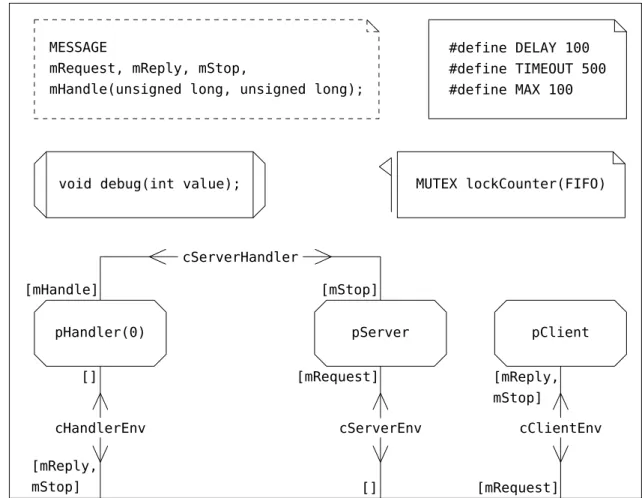
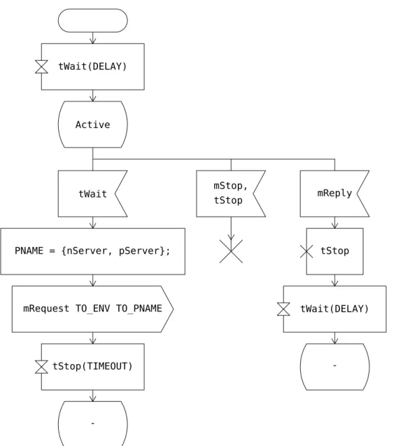
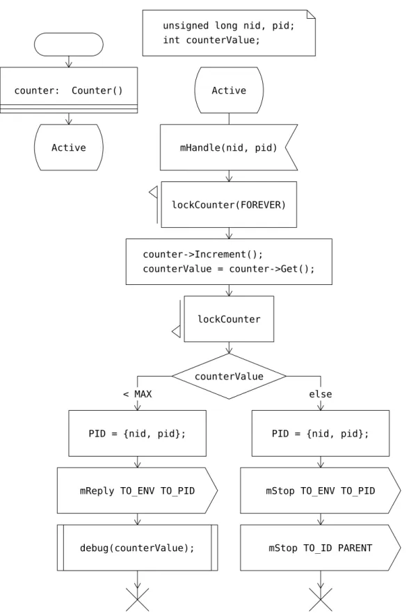
4.1 Specification and Description Language – Real Time . . . 41
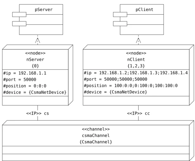
4.1.1 A Client-Server Application . . . 41 4.1.2 Architecture . . . 42 4.1.3 Communication . . . 45 4.1.4 Behavior . . . 45 4.1.5 Object Orientation . . . 51 4.1.6 Deployment . . . 52 4.2 Extensions . . . 53 4.2.1 Communication . . . 53 4.2.2 Deployment . . . 58 4.3 Conclusion . . . 63 5 Automation 65 5.1 State-of-the-art . . . 65
5.1.1 System Development Tools . . . 66
5.1.2 Interfaces and Code Transformation . . . 70
5.2 Code Generation . . . 72
5.2.1 Architecture and Behavior . . . 73
5.2.2 Communication . . . 93 5.2.3 Deployment . . . 102 5.3 Conclusion . . . 109 6 Visualization 111 6.1 Tracing . . . 111 6.1.1 Node Events . . . 112 6.1.2 Network Events . . . 114
6.1.3 Trace Generation and Format . . . 115
6.2 Trace Visualization . . . 115
6.2.1 Front-End . . . 116
6.2.2 Back-End . . . 119
6.3 Conclusion . . . 121
7 Case Study 123 7.1 The Client-Server Application . . . 123
7.2 Alarming Application for Earthquake Early Warning . . . 125
7.2.1 Earthquakes and Early Warning . . . 125
7.2.2 Earthquake Early Warning Systems . . . 129
7.2.3 SOSEWIN . . . 130
7.2.4 The Alarming Protocol . . . 133
7.2.5 Application Scenario . . . 137
8 Conclusions 145 8.1 Hypothesis . . . 145 8.2 Contributions . . . 145 8.3 Future Work . . . 146 8.3.1 Modeling . . . 146 8.3.2 Automation . . . 147 8.3.3 Visualization . . . 147 Bibliography 149 Acknowledgements 163 Declaration 165
This dissertation is about the development of distributed communication systems. A distributed communication system is a set of distributedprocessesthatinteractwith one another to meet a common goal. A process is an instance of a computer program in execution. It consists of a timed sequence of actions and events that depend on com-puter resources, operating system, and on other processes. Interaction is realized via messages transmitted between the processes through a communication network (Fig-ure 1.1). This implies that the processes run at different nodes of the communication network and are thus distributed.
Node 2 Communication Network Process 1 Process 2 Node N Process N Node 1
virtual link physical link
Figure 1.1: A distributed communication system as a set of interacting processes. A good example of a similar type of system would be that of a bridge construction site. Indeed, all people working at the site can be seen as processes. They perform a common task, that is the construction of the bridge. During work they communi-cate with each other and exchange materials needed for work, which is similar to the exchange of data between processes via messages. Communication between workers takes place over the air or telephone network. This is equivalent to the communication network that is used by the processes for interaction.
Distributed communication systems have gained a substantial importance over the past years. There is a large set of examples of systems that are present in our everyday
life. Examples of such systems are the world wide web (www), peer-to-peer networks, sensor networks, grid computing, etc. Some of them have applications in different do-mains, e.g., sensor networks are used in fire detection, weather monitoring, earthquake early warning, etc. The heterogeneity of applications and application domains speaks for the complexity of such systems and the challenges that developers are faced with. This complexity is due also to the existence of two sides of the system that need to be considered during development:
• the distributed communication infrastructure that includes the nodes (e.g., sensor nodes), communication medium (e.g., wifi), operating system, communication protocols, and
• the software applications running on top of the distributed infrastructure and providing services to the users (e.g., application deciding whether a fire alarm should be issued or not).
The focus of this dissertation is on the development of applications for distributed communication systems. There are two aspects that need to be considered during appli-cation development. The first and most obvious is the development of the appliappli-cation itself that will be deployed on the existing distributed communication infrastructure. The second and less obvious, but equally important, is the analysis of the deployed application. In simple terms, the purpose of the analysis is to show whether the ap-plication is delivering the requested services to the user according to specifications. This aspect of the development becomes crucial especially when the applications drive safety-critical systems. An example would be a misbehavior in the application that can lead to a situation where a fire alarm should be issued but it is not. Such misbehavior can lead to a life threatening situation and should be avoided by all means.
1.1 Problem Statement
Application development and analysis are like “two sides of the same coin”. An applica-tion cannot be deployed successfully unless its analysis confirms that the requirements are met. On the other hand, an accurate analysis is possible if the application has been deployed and is running on the intended distributed infrastructure. To solve this dead-lock, the common solution is to perform the analysis not on the application but on its abstraction. This abstraction can be seen as a selection of properties of the application relevant for analysis.
The separation between application development and analysis increases the cost and effort required during the development process. There are two factors that contribute to this increase. First, the method used for deriving the abstraction for analysis dif-fers from that used to develop the application, thus the derivation of an abstraction becomes a development process of its own. Second, because of the difference in the
development methods, a thorough validation process is required to ensure that the de-rived abstraction is an accurate representation of the application, otherwise the results obtained cannot be used for the analysis.
1.2 Approach
To decrease the development cost and effort, the approach of this dissertation is to combine and extend existing technologies for obtaining aunifieddevelopment method. Unification implies the use of the same development method for both application and analysis. This calls for a development method that is independent from its final prod-uct, be it the application ready for deployment or an abstraction of the later destined for analysis. The approach consist in capturing the aspects of the application at a higher level of abstraction. This allows the generation of artifacts that are independent from the final target, consequently they can be used to drive application development and analysis. Furthermore, the aim is to automatically derive an application ready to be deployed on a distributed communication infrastructure and its corresponding abstrac-tion to be used at the same time for analysis.
1.3 Hypothesis
The product of a unified development method is a unified description of the application that is independent from its final target (i.e., deployment or analysis). In addition, the description must capture the aspects of the application at sufficient level of detail so that the final target can be automatically derived. This calls for appropriate description means and an automated transformation mechanism. In this context, the hypothesis of this dissertation is that:
The properties of the application can be captured in a unified description which can drive automatic transformation for deployment on real infrastructures and/or analysis.
1.4 Contributions
The contributions of this dissertation can be summarized as follows:
• an approach for capturing the aspects of an application and producing a unified description of it,
• an approach for automatically transforming this description into:
– the application itself, to be deployed on the intended distributed communi-cation infrastructure, and
– an accurate simulation model of the application to be used for analyzing its properties,
• an approach for an in-depth analysis of the system that:
– captures all events during runtime and stores them appropriately, and – visualizes all captured events to drive analysis.
Furthermore, tool support is provided for each of these approaches, and a real-world case study is reported for demonstrating their feasibility and the usability of the tools.
1.5 Structure
This dissertation is structured as follows:
• Chapter 2 introduces the terminology that serves as foundation for this work. • Chapter 3 positions this work in relation to existing state-of-the-art.
• Chapter 4 presents the approach for capturing the aspects of the application and producing a unified description of it.
• Chapter 5 presents the approach for automatic transformation for deployment and simulation.
• Chapter 6 presents the approach for visual in-depth analysis of the application. • Chapter 7 reports the development of an alarming protocol for earthquake early
warning as a real-world case study. • The dissertation concludes in Chapter 8.
This dissertation covers the fields ofmodel-driven development,simulation, and visual-ization of distributed communication systems. A brief introduction of these systems was given in Chapter 1. This chapter introduces the terminology which serves as the foundation for this work. At first, a definition for the model and model-driven de-velopment is given. These allow capturing of relevant properties of the system in a unified description. The second part focuses on simulation as the method used in this dissertation for experimentation and analysis. The chapter concludes by introducing the concept of visualization.
2.1 What is a Model?
The term model is widely used in several domains. Mathematics, physics, biology, social science, civil engineering, software engineering, and many more make frequent use of the term. These domains have their own definition of the model, however, all definitions can be seen as a more detailed description of the very generic definition: A model is anything that is (or can be) used, for some purpose, in place of something else[1]. Although very generic, this definition captures all key aspects present in every model definition. The first aspect is that a modelcan be anything. This is very true considering that a model can be:
• a formula representing a law in physics,
• a miniature representation of a bridge in some kind of material,
• code in a programming language representing a computer program, etc.
The second aspect is that the modelserves some purpose. Considering the given exam-ples, the purpose of the listed models can be:
• a formula in physics is used for calculations,
• code is used by programmers to transform their ideas into computer programs with the help of compilers, etc.
The last aspect has to do with the model replacingsomething else. This usually means that, for the indented purpose, the model is used instead of what it represents:
• a physical law in itself is impossible to use in calculations, thus a formula seems appropriate,
• it is almost impossible to test the bridge itself for wind resistance, thus a miniature representation is used,
• it is quite challenging expressing ideas in digital signals (0s and 1s), thus program-ming languages are used, etc.
Having a general definition of the model, it is time to place it in the context of this dissertation.
2.1.1 Software Models
Based on the definition given in Chapter 1, a distributed communication system is a set of interacting processes as part of a computer program in execution. In simple terms, the system is the computer program in execution on the distributed communication in-frastructure. According to the definition of the model, the whole development process of such systems is based on models. This is true because every computer program is de-rived from code artifacts. These artifacts are a representation of the computer program (a model of it), and they are used by the compiler to obtain an executable form (the computer program itself). In this case the model must capture all properties of what it represents, i.e., the code describes everything the computer program will do, and the program will do what the code tells. This tight coupling between the code and the computer program derived from it often creates the idea that they are the same thing. This idea is deeply embedded in the terminology used today, i.e., the process of writing code is called programming (as in building a program) and not modeling (as in building a model of a program).
Modeling in software development is usually associated with some other description method that is not code. A typical and very popular example of this is the UML class diagram [2], which captures the static structure of a program using classes, attributes, operations, and relations. It is much easier to relate this case to the definition of the model, because class diagrams capture only static properties (not everything like the code does) and they are used for better understanding this static structure (not for gen-erating the program through a compiler). Of course they can be used to generate code, but it will not be complete and thus not enough for generating the final executable. Nevertheless, this code can suffice for generating another computer program that can
be executed just for analyzing the structural properties captured by the class diagram. This other program can be seen as a reduced representation of the complete program, and thus it can be characterized as a model of it. In summary, three important aspects of models of computer programs are identified:
• they can capture all or part of the properties of the program they represent, • the program can be derived from its model in case the later captures all properties, • a partial program can be derived when part of properties are captured for
analyz-ing those properties.
2.2 Model-Driven Development
The general definition of the model presented in Section 2.1 does not impose any re-strictions on the existence of what a model is representing. This is true considering for instance the example of the bridge. The model of the bridge used for testing its wind resistance is usually built before the bridge itself. This is understandable because the bridge cannot be build unless the tests on its model fulfill the safety requirements. An-other aspect to be noted in this example is that the bridge will be build using its model (that passed the wind resistance test) as a reference. In this case the model of the bridge is used for building the bridge itself. So, in a nutshell:
Model-driven development (MDD) is simply the notion that we can construct a model of a system that we can then transform into the real thing [3].
This definition includes three key elements in it:
• appropriate means are required to construct a model of the system, e.g., relevant materials and tools in case of the model of the bridge,
• appropriate means are required totransform the model into the real thing, e.g., architects, engineers, and machines for building the bridge,
• the properties of the model are transferred to thethe real thing, e.g., safety prop-erties are present in both the model and the bridge itself.
A development approach must include these three elements in order to be considered as model-driven.
2.2.1 Model-Driven Software Development
Based on the definition of MDD, any software development approach is in itself model-driven. This is true because:
• programming languages are the tools used to write code, which represents the model of a computer program,
• compilerstransformthe code into the actual computer program, and
• the computer program does what the code tells, meaning that all properties ex-pressed in code aretransferred to the program.
If the above statement is true then why introduce the term model-driven software de-velopment(MDSD)? The answer to this question can be found in the key elements of model-driven development listed Section 2.2 and specifically to theappropriate means. There exist several types of software depending on the application domain. Thesetypes usually differ from one another because the set of properties they need to capture is strictly connected to the domain. For example, the accounting software used in a bank does not care about interpreting signals about room temperature or smoke. In the same way, the fire alarming software in the same bank does not care about the account balance of a customer. This heterogeneity implies the availability of means to capture properties from different domains. These means are of course present in most program-ming languages. That is why they are able to model software for different application domains and often associated with the termgeneral purpose language(GPL). Although possible, the development of complex software (e.g., distributed communication sys-tems) using GPLs requires considerable skills and time, which are translated into an increase in cost and effort.
The goal of MDSD is to increase the level of abstraction in software description so that its properties are captured in a way that is closer to the application domain and thus decreasing cost and effort required in the process. This is realized with the introduction ofsoftware modeling languages(e.g., UML) and transformation technologies. In MDSD the modeling language is used to capture the properties and produce a software model which is transformed into code ready to be compiled for obtaining its executable form (the computer program). An important concept introduced here is transformation or simplycode generation. In principle there are two approaches to code generation:
• The code is generated manually using the model as a reference. If this approach is adopted then the focus of the development will be the code and not the model. This will shift the development process towardsmodel-based, where the models, although important, do not drive the process itself. Due to this shift there is a risk for the models to be used only for documentation purposes. Also, inconsistencies between the model and the code are not rare.
• The code is generated automatically. This implies the existence of computer pro-gram (the code generator) that can transform the model into code. Furthermore, the generated code must not require further manual modification, but it should be ready for compilation.
Automation is the heart ofpragmaticMDSD [4]. Also, it is important for MDSD to be able to take advantage of legacy code libraries and other legacy software [4]. This is crucial for complex software like distributed communication systems, where the ap-plication cannot provide its service without interacting with the underlying communi-cation infrastructure. This requires a description mechanism that allows integration of operating system calls or protocol interfaces inside software models. Also, this mecha-nism must provide means for integrating simulation libraries in case the final product of the code generator is a computer program destined for analysis through simulation.
2.3 Simulation
One of the reasons why models exist isexperimentation. Experimentation methods can be classified as shown in Figure 2.1.
Experiment with the System Experiment with a Model of the System
Physical Model Mathematical Model
Simulation Analytic Analysis
System
Figure 2.1: Methods of experimentation for system analysis.
Although not explicitly, the concept of experimentation was introduced already in the example of the bridge. Recall that the model of the bridge was used to test its wind resistance. These tests are a series of experiments in a wind tunnel with the purpose of analyzing those properties of the bridge related to wind resistance. The results of this analysis can be used to decide whether the safety requirements are met.
Simulation is the imitation of the operation of a system over time, for the purpose of better understanding and/or improving that system [5, 6].
Imitation and system are synonyms with model and what the model represents. This implies a strong relation between models and simulation. That is why the imitation is usually referred as the simulation model. While models in general can capture any properties, simulation models lean towards dynamic properties, i.e., those properties that characterize operation over time. Also, simulation models usually do not capture all properties but only those relevant to the analysis.
The focus of this dissertation is oncomputer simulation. In computer simulation the model is a computer program (in execution). The properties of the bridge that are af-fected by the wind over time can be also captured by a set of mathematical equations expressed in program code. The same can be stated for the wind properties that affect the bridge. These pieces of code can be combined together and then compiled to pro-duce an executable computer program. The purpose of this computer program is the same with that of the miniature (physical) model of the bridge in the wind tunnel, that is testing for wind resistance. Computer simulation can be very useful in cases where construction of a physical model is impossible or cost and effort inefficient. Another advantage is the ability to easily change or modify captured properties without having to rebuild the model from scratch, which is not possible with physical models.
2.3.1 Discrete Event Simulation
Simulation models can be classified depending on how time advances during simulation. Two basic methods of advancing time in simulation aretime-steppinganddiscrete-event. Time-stepping implies advance in small time increments, where time is represented as a continuous variable. It is suitable for simulating systems whose properties can be captured with a set of differential equations. Discrete-event simulations are executed by processing a series of events and not by directly advancing time. Discrete event simulation models generate and process events, where each generated event is stamped with the time at which it needs to be processed. The simulator keeps track all of pending events (events to be processed) in a data structure called the event list, which allows the simulation to determine the event to be processed next. The current time can be viewed as the minimum time-stamp in the event list, that is the time associated with the first event in the list. Two main approaches can be used for the development of discrete event simulations:
• Theevent-orientedapproach uses events as its basic modeling construct. Employ-ing an event-oriented approach to model a system is akin to usEmploy-ing assembly lan-guage to write a computer program: it is very low-level and consequently more efficient and difficult to use; especially for larger systems.
• The process-oriented approach describes a system as set of interacting processes and uses a process as the basic modeling construct. A process is used to encap-sulate a portion of the system as a sub-model in the same way classes do in an
object-oriented programming language. Typically, process-oriented simulation models are built on top of event-oriented simulators.
2.3.2 Simulation of Software Systems
The process of constructing a simulation model is not trivial. It is simpler to exper-iment with a physical model, taking for granted that the physical model can be con-structed efficiently. For example, the construction of a miniature model of the bridge will be like that of constructing the bridge itself. On the other hand, constructing a mathematical model of the bridge is not straightforward because the methodology and expertise required differs from that required to construct the bridge itself. This change in methodology requires for the models to be valid, otherwise the results of simulation will be useless. Computer simulation does require a change in methodology, but there are cases where it is a better choice. These are the cases where computer simulation is used for experimentation of software. Indeed, both software and its simulation model are computer programs in execution. Nevertheless, they are by no means the same considering that the code used to derive each of them is not the same. So in principle, to take advantage of this similarity, an abstraction mechanism is required to capture the properties of the software independently from the final target, i.e., the actual com-puter program or its model for simulation. This mechanism can be provided by the model-driven software development paradigm.
2.4 Visualization
According to the definition given in Section 2.3, the purpose of simulation (and ex-perimentation in general) is better understanding and/or improvement. In this context, experimentation with a physical model is better suited than computer simulation. In-deed, the reaction of a bridge to different wind speeds and directions can be better understood on a miniature model than with a set of numbers (data) produced by com-puter simulation. This is due to the change in methodology introduced in Section 2.3.2. To solve this problem, the data has to be presented somehow in a form closer to the do-main. This can be achieved with a recovery mechanism to the change in methodology so that the results of computer simulation can be presented with something closer to a physical model. This mechanism can be provided bycomputer visualization.
Visualization is the use of computer-supported, interactive, visual representations of data to amplify cognition [7].
In the example of the bridge computer graphics can be used to construct a 3D model of the bridge. The data resulting from simulation can animate this graphical model to mimic its behavior on wind conditions.
This chapter introduces state-of-the-art methods and technologies for the development, simulation, and visualization of distributed communication systems. In the first part the focus is on modeling languages as the core component of any model-driven ap-proach. The selection of the languages is done based on their capabilities for capturing the properties of distributed communication systems in a sufficient level of abstrac-tion. The possibility of their usage in a pragmatic model-driven approach is discussed in terms of technologies and tools. The second part focuses on the simulation of dis-tributed systems. Here the most popular simulation frameworks and/or libraries are introduced. The third part introduces existing work that uses a model-driven approach for the development and simulation of distributed communication systems. A discus-sion is made on whether the presented works provide a complete pragmatic model-driven approach. The final part is dedicated to related contributions on visualization of distributed communication systems.
3.1 Modeling Languages
The modeling language is the heart of model-driven development. It provides the nec-essary abstractions for capturing the properties in form of artifacts. These artifacts are then used as inputs for an automated mechanism (code generation) that transforms these descriptions into code to be compiled for obtaining the computer program for deployment and a simulation model of it for experimentation.
There exist several modeling languages for distributed communication systems. The focus here is on popular and/or standardized modeling languages. Standardization is an important aspect because it provides a significant impetus for further progress because it codifies best practices, enables and encourages reuse, and facilitates inter-working between complementary tools [4].
The languages are introduced in the following paragraphs by shortly describing their approach for capturing the properties of distributed communication systems. These properties are:
• Structure– What are the building blocks (or components) of the system and how are they organized?
• Behavior – How do these components perform their activities (functional prop-erties)?
• Communication– How do they communicate with each-other to perform their activities?
• Deployment– How are they deployed on the distributed communication infras-tructure?
This section concludes with a discussion about the potential use of these languages in a model-driven development approach.
3.1.1 LOTOS
LOTOS (Language of Temporal Ordering Specification) [8] is a formal description technique1developed within ISO (International Standards Organization) for the formal specification of distributed systems. There exist a number of LOTOS tutorials in the literature [10, 11]. This paragraph gives a very brief overview of the language in the context of the dissertation.
LOTOS specifications consist of two parts: the Abstract Data Types(ADT) and the Control. The ADT part defines the data types and value expressions needed to specify the behavior of a system. It is based on the formal theory of algebraic abstract data types ACT-ONE [12]. The Control part describes the internal behavior of the system. It is defined by abehavior expressionfollowed by possibleprocess definitions. A behavior expression is built by combining LOTOSactions by means of operators and possibly process’ instantiations.
Process A process describes the behavior of a physical or logical entity in the system or a function. It appears as a black-box to its environment, i.e., the process’ internal behav-ior is hidden to the environment. The encapsulation provided by the process concept makes this part of the language highly suitable for specifying communicating objects in a telecommunication system. A process is also defined by a behavior expression.
Gate A process interacts with its environment by means of synchronization at com-mon points called gates. Gates may be used to model logical or physical interfaces between a system and its environment. Values, specified by the ADT, may be passed and received at these gates.
Action The basic units in a behavior expression are actions. They are atomic, instan-taneous, and synchronous behaviors. Each action is associated with a gate, namely the gate at which the event occurs. Two types of actions exist in LOTOS. There are actions that need to synchronize with the environment of the process in order to be executed; and there are internal actions, that a process can execute independently.
1Aformal descriptionis a description expressed in a language whose vocabulary, syntax, and semantics
3.1.2 Estelle
Estelle [13] is a formal description technique, also developed within ISO, for the formal specification of distributed, concurrent information processing systems. An overview of the language is also given in [14, 15]. Estelle may be viewed as a set of extensions to ISO Pascal [16] that model a system as a hierarchical structure of automata which:
• may run in parallel, and
• may communicate by exchanging messages and/or by sharing variables.
A distributed system is composed of several communicating components; each com-ponent is specified by a module definition. The module definition consists in a set of actions (transitions). A module is active if its definition includes at least one transi-tion; otherwise, it is inactive. Each module has a number of input/output access points called interaction points, which can be external or internal. Achannel is associated to each interaction point. Interactionsare abstract events (messages) exchanged with the module environment (through external interaction points) and with children modules (through internal interaction points).
Structure A module definition in Estelle may include definitions of other modules. This leads to a hierarchical tree structure of module definitions. Estelle provides means to create instances of child modules defined within the module definition.
Communication Module instances within the hierarchy can communicate. Two com-munication mechanisms can be used in Estelle:
• In amessage exchangea module can send interactions to another module through a previously established communication link between their two interaction points. An interaction received by a module instance at its interaction point is appended to an unbounded FIFO queue associated with this interaction point. The FIFO queue either exclusively belongs to the single interaction point (individual queue) or it is shared with some other interaction points of a module (common queue). • Inrestricted sharing of variablescertain variables can be shared between a module
and its parent module. These variables have to be declared as exported variables by the module.
Behavior The behavior of a module is expressed in terms of a nondeterministic state transition system. The initial state of a module is defined in the initialization part of the module definition. The next-state-relation of a module is defined by a set of transitions declared within the transition part of the module definition. Each transition definition contains necessary conditions enabling the transition execution, and an action to be performed when it is executed. An action may change the module state and may output interactions to the module environment. Actions are defined using Pascal. The well known model of finite state automaton (FSA) is a particular case of a state transition system, hence it may be described in Estelle.
3.1.3 UML
UML (Unified Modeling Language) [2] is a general-purpose visual modeling language standardized by OMG (Object Management Group). It is used to specify, visualize, construct, and document the artifacts of a software system. It is intended for use with all development methods, life-cycle stages, application domains, and media. UML in-cludes semantic concepts, notation, and guidelines. It has static, dynamic, environmen-tal, and organizational parts. The UML specification [2] does not define a standard process but is intended to be useful with an iterative development process.
The UML captures information about the static structure and dynamic behavior of a system using the set of diagrams shown in Figure 3.1.
Communication Structure Timing UML Diagram Behavior Profile Class Composite Structure Component Interaction Overview Deployment Object Package Activity Interaction State Machine Use Case Sequence
Figure 3.1: The UML diagrams.
A system is modeled as a collection of discrete objects that interact to perform work that ultimately benefits an outside user. The static structure defines the kinds of objects important to a system and to its implementation, as well as the relationships among the objects. The dynamic behavior defines the history of objects over time and the communications among objects to accomplish goals. Modeling a system from several
separate but related viewpoints permits it to be understood for different purposes.
Structure Diagrams Structure diagrams show the static structure of the system, its parts, and their relations on different abstraction levels. The elements in a structure diagram represent the meaningful concepts of a system, and may include abstract, real world, and implementation concepts. Structure diagrams do not usetime related con-cepts, i.e., do not show the details of dynamic behavior.
• The class diagram describes the structure of a system by showing the system’s classes, their attributes, and the relationships among the classes.
• Theobject diagramshows a complete or partial view of the structure of a modeled system at a specific time.
• The package diagram describes how a system is split up into logical groupings (packages) by showing the dependencies among these groupings.
• The component diagram describes how a software system is split up into compo-nents and shows the dependencies among these compocompo-nents.
• The composite structure diagramdescribes the internal structure of a class and the collaborations that this structure makes possible.
• The deployment diagramdescribes the hardware used in system implementations and the execution environments and artifacts deployed on the hardware.
• The profile diagramis an auxiliary diagram which allows defining custom stereo-types, tagged values, and constraints. It has been defined in for providing a light-weight extension mechanism to the UML standard.
Behavior Diagrams Behavior diagrams show the dynamic behavior of the objects in a system, which can be described as a series of changes to the system over time.
• The use case diagramdescribes the functionality provided by a system in terms of actors, their goals represented as use cases, and any dependencies among those use cases.
• The activity diagram describes the business and operational step-by-step work-flows of components in a system.
• The state machine diagram is used for modeling discrete behavior through finite state transitions.
• The interaction diagrams, a subset of behavior diagrams, emphasize the flow of control and data among the things in the system being modeled:
– The sequence diagram shows how objects communicate with one another in terms of a sequence of messages. It also indicates the lifespans of objects relative to those messages.
– Thecommunication diagramshows the interactions between objects or parts in terms of sequenced messages. They represent a combination of informa-tion taken from class, sequence, and use case diagrams describing both the static structure and dynamic behavior of a system.
– The interaction overview diagram provides an overview in which the nodes represent communication diagrams.
– Thetiming diagramsis a specific type of interaction diagram where the focus is on timing constraints.
3.1.4 SDL
SDL (Specification and Description Language) [17] is a formal description technique developed by ITU-T (International Telecommunication Union - Telecommunication Standardization Sector) for the formal specification and description2 of telecommuni-cation systems. The language is used in the development of advanced technical systems, e.g., real-time systems, distributed systems, and generic event-driven systems where parallel activities and communication are involved. Typical application areas are high-and low-level telecommunication systems, aerospace systems, high-and distributed or highly complex mission-critical systems.
A basic model of a system in SDL consists of a set of extended finite state machines (FSMs) that run in parallel. These machines are independent of each other and com-municate with discrete signals.
Structure SDL comprises four main hierarchical levels: system, blocks, processes, and procedures. Each SDL process is defined as a nested hierarchical state machine. Each sub state machine is implemented in a procedure. Procedures can be recursive; they are local to a process or they can be globally available depending on their scope. SDL also supports the remote procedure paradigm, which allows one to make a procedure call that executes in the context of another process. A set of processes can be logically grouped into a block (subsystem). Blocks can be nested inside each other to recursively break down a system into smaller and maintainable encapsulated subsystems.
Communication SDL does not use any global data. SDL has two basic communi-cation mechanisms: asynchronous signals (and optional signal parameters) and syn-chronous remote procedure calls. Both mechanisms can carry parameters to inter-change and synchronize information between SDL processes and with an SDL system and its environment (e.g., non-SDL applications or other SDL systems). SDL defines clear interfaces between blocks and processes by means of a combined channel and sig-nal route architecture. SDL defines time and timers in a clever and abstract manner.
2According to [17]: aspecificationof a system is the description of its required behavior; and a
Time is an important aspect in all real-time systems but also in distributed systems. A SDL process can set timers that expire within certain time periods to implement time-outs when exceptions occur but also to measure and control response times from other processes and systems. When a SDL timer expires, the process that started the timer receives a notification (signal) in the same way as it receives any other signal. Actually an expired timer is treated in exactly the same way as a signal. SDL time is abstract in the sense that it can be efficiently mapped to the time of the target system, be it an operating system timer or hardware timer.
Behavior The dynamic behavior in a SDL system is described in the processes. The system/block hierarchy is only a static description of the system structure. Processes in SDL can be created at system start or created and terminated at run time. More than one instance of a process can exist. Each instance has a unique process identifier (PID). This makes it possible to send signals to individual instances of a process.
Data SDL accepts two ways of describing data, abstract data type (ADT) and ASN.1 [18]. The integration of ASN.1 enables sharing of data between languages as well as reusing existing data structures. The ADT concept used within SDL is very well suited to a specification language. An abstract data type is a data type with no specified data structure. Instead, it specifies a set of values, a set of operations allowed, and a set of equations that the operations must fulfill. This approach makes it simple to map an SDL data type to data types used in other high-level languages.
3.1.4.1 SDL UML Profile
The SDL UML Profile [19] allows transition from the more abstract UML models to the unambiguous SDL models. A SDL model can be treated as a specialization of the generic UML model thus giving more specific meaning to entities in the applica-tion domain (e.g., blocks, processes, channels, etc.). A number of features have been introduced in SDL which directly support SDL and UML convergence:
• UML-style class symbols provide both partial type specifications and references to type diagrams containing the definition of that type;
• UML-style graphics for SDL concepts such as types, packages, inheritance, and dependencies;
• composite states that combine the hierarchical organization of state machine dia-grams with the transition-oriented view of SDL finite state machines;
• interfaces that define the encapsulation boundary of active objects; and • associations between class symbols.
While UML has its focus and strength on object oriented data modeling, SDL has its strength in the modeling of concurrent active objects, of the hierarchical structure of active objects, and of their connection by means of well-defined interfaces.
3.1.4.2 SDL-RT
SDL-RT (Specification and Description Language - Real Time) [20] is based on the SDL standard extended with real time concepts. It introduces support of UML in order to extend SDL-RT usage to static parts of the embedded software and distributed systems. SDL-RT builds on the fact that SDL is not suited for any type of coding. Some parts of the application still need to be written in C, C++, or other programming languages. Furthermore, legacy code or off the shelf libraries such as operating systems, protocol stacks, and drivers have C/C++ programming interfaces. Last but not least, there are no SDL compilers so SDL needs to be translated into C code to get down to the target. So all SDL benefits are lost when it comes to real coding and integration with real hardware and software. Considering these limitations, SDL-RT provides real time extension to SDL based on two basic principles:
• replace SDL data types by C/C++ data types and • add semaphore support.
Also, UML diagrams have been added to SDL-RT to extend its application field: • The class diagram brings a perfect graphical representation of the classes’
orga-nization and relations. Dynamic classes represent SDL agents and static classes represent C++ classes.
• Thedeployment diagramis used to describe distributed systems. It offers a graph-ical representation of the physgraph-ical architecture and how the different nodes com-municate with each other.
3.1.5 Outlook
In addition to the modeling languages listed above, there exist a number of other lan-guages that are used in research and/or industry. Relevant lanlan-guages are:
CPN Colored Petri Nets [21] is a language for modeling and validation of concurrent and distributed systems and other systems in which concurrency, synchronization, and communication plays a major role. The CPN modeling language is supported by the computer tool CPN Tools [22]. CPN are quite popular and find use in several appli-cations [23, 24, 25, 26, 27, 28]. CPN have been used also for the verification of UML [29, 30] and SDL [31, 32] models.
PROMELA The Process or Protocol Meta Language [33] is a verification modeling language that allows for the dynamic creation of concurrent processes to model, for ex-ample, distributed systems. The models can be analyzed with the SPIN model checker [33]. There exist several application examples from different domains [34, 35, 36, 37]. As in CPN, efforts were made to verify UML [38] and SDL [39] models in PROMELA. The reason why these languages are left outside this discussion is that they focus only on system analysis3and not on their development.
The first issue to consider in the assessment of the introduced languages is whether they provide description means for capturing the aspects of distributed communication systems listed at the beginning of this chapter, i.e., structure, behavior, communication, and deployment. All languages have support for the first three aspects, with Estelle and SDL providing a clear, distinct, and formal definition. Although UML does make a distinction by means of its diagrams, the concepts are not formalized and leave room for interpretation. These deficiencies of UML are referred as its variation points. A distinction between the languages can be made regarding the fourth aspect, i.e., deploy-ment. From the four languages taken in consideration only UML mentions explicitly (although not formalized) such concept in its deployment diagram. It is important to mention here also the fact that, because of its popularity, an effort was made to formal-ize such concepts in the context of SDL by means of eODL [40]. Unfortunately the language did not find any real application due to overlapping concepts with UML. Nev-ertheless, such aspect can be captured by using the UML-SDL profile as it is actually an UML description and can be combined with existing UML notations, i.e., the deploy-ment diagram. A more direct approach would be to use SDL-RT, because it explicitly defines deployment in combination with SDL as part of its supported concepts.
The second issue regards the possible use of the listed languages in a model-driven development approach. There are two aspects to consider here, given that the lan-guage does provide the description means used to capture the aspects of interest. First is automation, that is the possibility to fully automate code generation for the com-puter program to be deployed on the distributed communication infrastructure and the computer program to be used for experimentation via simulation. Automation im-plies the availability of tools.4 This is what sets apart languages like LOTOS or Estelle with languages like UML or SDL. Although standardized, LOTOS and Estelle did not experience the same popularity and applicability of UML and SDL. There are a lot of application examples that speak for this popularity and also the history of the up-dated standards [2, 17]. The second aspect concerns the possibility to integrate legacy software. This is an important part of pragmatic model-driven development, because it allows existing software running on the distributed infrastructure (e.g., communi-cation protocols) to be used within the model. Integration of such software may be
3The focus in on verification and validation.
4Tool here is used as short for computer programs that transform system descriptions in a modeling
crucial for providing the required services to the user (e.g., distributed communication is not possible without access to communication protocols). This requires a certain flexibility from the modeling language defined into concepts for making such integra-tion possible. Unfortunately neither of the languages do provide such means, at least not in their standard form. Regarding LOTOS, Estelle, and SDL the inclusion of such concepts will make them informal. This is because support for such concepts in itself means inclusion of existing code into the model. However, these concepts are not sup-ported even in UML. A reason for this may be the complexity of the language as it is and the large set of programming languages in which code may be written. This issue is addressed in SDL-RT, where C/C++ code can be included in the model. Of course, SDL-RT is neither standardized nor formal, but it can be seen as a combination of stan-dardized languages (i.e., SDL, UML, and C/C++ [41, 42]) for pragmatic model-driven development.
3.2 Simulation
There are two approaches to simulation in general, which is true also for distributed communication systems, i.e., build a simulation model from scratch or use existing sim-ulation software. The first approach may produce more accurate results as the whole process of building a simulation model is part of the development, i.e., no external mod-els are used. However, this approach will become soon unfeasible with the increasing of complexity, which is actually the case of distributed systems. Also, the underlying communication infrastructure is not the primary focus, as opposed to the application running on top of it. On the other hand, accurate simulation models of the commu-nication infrastructure are crucial to simulation, and as such they must have the same order of priority during development. Nevertheless, the adoption of the first approach would require the construction of such models from scratch, which is neither time nor cost effective. That is why in these cases the second approach (i.e., reuse of existing simulation software) sounds more feasible.
This section gives an overview of the most popular simulation software used in the field of computer communication and networking which provide simulation models of the underlying communication infrastructure. The focus is on key design choices and models they provide. The section concludes with some remarks on whether the presented simulation software can be used in a model-driven approach.
3.2.1 ns-2
The Network Simulator 2 (ns-2) [43, 44] is an event-driven simulation tool for studying the dynamic nature of communication networks. It has gained constant popularity in the networking research community since its birth in 1989. Ever since, several revo-lutions and revisions have been made. The group of researchers and developers in the
community are constantly working to keep ns-2 strong and versatile.
Two languages are used in ns-2: OTcl [45] and C++. The reason behind this choice was to make writing simulation scripts easy and flexible in Tcl, while implementing the performance critical code in C++. Tcl is an interpreted language, thus changes to a simulation script do not require any recompilation. However, this flexibility comes at the cost of slower execution speed. Also, due to this dual language design, all objects need to be available in both languages and must provide dual interfaces in C++ and OTcl.
Figure 3.2 shows a generic simulation model in ns-2. Thenodeis the basic component and serves as a communication endpoint where other components may be attached to. The link represents the communication medium that connects nodes and can be one-way or two-way. Every packet that needs to be transmitted over the link is first inserted into itsqueue, and when the link is ready to handle it, it is removed from the queue and delivered to the destination after somedelay. Queues and delays are available for both communication ways when the link is duplex. After the underlying physical infrastructure has been set (i.e., the nodes and links), the next step would be to define the protocols so that communication can be possible. Protocols in ns-2 are represented byagentsattached to nodes. The infrastructure is now ready to be used byapplications (also known as traffic generators) for communication. Applications are attached to agents and use the protocols to communicate with each other.
Application Agent Node Queue Delay Queue Delay Agent Link Node Application
Figure 3.2: The basic simulation model in ns-2.
3.2.2 ns-3
The Network Simulator 3 (ns-3) [46, 47] is a discrete-event network simulator targeted primarily for research and educational use. One of the fundamental goals in the ns-3 design was to improve the realism of the models, i.e., to make the models closer in implementation to the actual software implementations that they represent. Different
simulation tools have taken different approaches to modeling, including the use of spe-cific modeling languages, code generation tools, and component-based programming paradigms. While high-level modeling languages and simulation-specific programming paradigms have certain advantages, modeling actual implementations is not typically one of their strengths. In the authors’ experience [47], the higher level of abstraction can cause simulation results to diverge too much from experimental results, and there-fore an emphasis was placed on realism. For example, ns-3 chose C++ as the program-ming language because it facilitated the inclusion of C-based implementation code. The ns-3 architecture is also similar to Linux computers, with internal interfaces (network to device driver) and application interfaces (sockets) that map well to how computers are built today. ns-3 is not a new simulator but a synthesis of several predecessor tools, including ns-2, GTNetS [48], and YANS [49]. A third emphasis has been on ease of debugging and better alignment with current languages. Architecturally, this led the ns-3 team away from the mixture of OTcl and C++ which was hard to debug. Instead, the design chosen was to emphasize purely C++-based models for performance and ease of debugging, and to provide a Python-based scripting interface.
As shown in Figure 3.3, the ns-3 simulator has models for all the various elements of a computer network. Channel Application Node Device Device Application Protocol Stack Node Protocol Stack Packet Socket-like API
Figure 3.3: The basic simulation model in ns-3.
• Nodesrepresent both end-systems such as desktop computers and laptops, as well as network routers, hubs, and switches.
• Devicesrepresent the physical device that connects a node to a communication channel. This might be a simple Ethernet network interface card, or a more complex wireless IEEE 802.11 device.
• Channels represent the medium used to send the information between network devices. These might be fiber-optic point-to-point links, shared broadcast-based media such as Ethernet, or the wireless spectrum used for wireless communica-tions.
• Protocolsmodel the implementation of protocol descriptions found in the various Internet Request for Comments (RFC) documents, as well as newer experimental protocols not yet standardized. These protocol objects typically are organized into a protocol stack where each layer in the stack performs some specific and limited function on network packets, and then passes the packet to another layer for additional processing.
• Packetsare the fundamental unit of information exchange in computer networks. Nearly always a network packet contains one or more protocol headers describ-ing the information needed by the protocol implementation at the endpoints and various hops along the way. Also, the packets typically contain payload which represents the actual data (such as the web page being retrieved) being sent be-tween end systems. However, it is not uncommon for packets to have no payload, such as packets containing only header information about sequence numbers and window sizes for reliable transport protocols.
• Applicationsare traffic generators, i.e., they communicate by sending and receiv-ing packets through the network usreceiv-ing asocket-likeinterface.
In addition to the models for the network elements mentioned above, ns-3 has a number of helper objects that assist in the execution and analysis of the simulation, but are not directly modeled in the simulation. These are:
• Random variables can be created and sampled to add the necessary randomness in the simulation. Various well-known distributions are provided, including uni-form, normal, exponential, Pareto, and Weibull.
• Trace objectsfacilitate the logging of performance data during the execution of the simulation, that can be used for later performance analysis. Trace objects can be connected to nearly any of the other network element models, and can create the trace information in several formats.
• Helper objects are designed to assist with and hide some of the details for vari-ous actions needed to create and execute an ns-3 simulation. For example, the CsmaHelperprovides an easy method to create an Ethernet network.
• Attributes are used to configure most of the network element models with a rea-sonable set of default values. These default values are easily changed either by specifying new values on the command line when running the ns-3 simulation, or by calling specific functions in the default value objects.
3.2.3 OMNeT++
The Objective Modular Network Testbed in C++ (OMNeT++) [50, 51, 52] is an extensible, modular, and component-based C++ simulation library and framework. It has been created with the simulation of communication networks and other distributed systems in mind as application area, but instead of building a specialized simulator, it was designed to be as general as possible. OMNeT++ is often quoted as a network simulator, when in fact it is not. It includes the basic machinery and tools to write simulations, but itself it does not provide any components specifically for computer networks, queuing networks, or any other domain. These application areas are sup-ported by various simulation models and frameworks:
• INET Framework [53] is an open-source communication networks simulation package, which contains models for several Internet protocols: UDP, TCP, SCTP, IP, IPv6, Ethernet, PPP, IEEE 802.11, MPLS, OSPF, and others.
• INETMANET [54] is a fork of the INET Framework, and extends INET with support for mobile ad-hoc networks. It supports AODV, DSR, OLSR, DYMO and other ad-hoc routing protocols.
• OverSim [55] is an overlay and peer-to-peer network simulation framework for OMNeT++. The simulator contains models for structured (Chord, Kademlia, and Pastry) and unstructured (GIA) P2P systems and overlay protocols. OverSim is also based on the INET Framework.
• MiXiM [56] supports wireless and mobile simulations. It provides detailed mod-els of the wireless channel, wireless connectivity, mobility modmod-els, modmod-els for obstacles and many communication protocols especially at the MAC level. • Castalia [57] is a simulator for Wireless Sensor Networks (WSN), Body Area
Networks, and generally networks of low-power embedded devices. Castalia can be used by researchers and developers to test their distributed algorithms and/or protocols in a realistic wireless channel and radio model, with a realistic node behavior especially relating to access of the radio.
The OMNeT++ simulation model is shown in Figure 3.4. It consists of modules that communicate with message passing. The active modules are namedsimple modules; they are implemented in C++ using the simulation class library. Groups of modules can be encapsulated intocompound modules.
In network simulations, simple modules may represent user agents, traffic sources and sinks, protocol entities, network devices, data structures, or user agents that gener-ate traffic. Network nodes such as hosts and routers are typically compound modules assembled from simple modules. Both simple and compound modules are instances of module types. While describing the model, the user defines module types; instances of
Compound Module
Simple Module Network
Connection Gate
Figure 3.4: Model structure in OMNeT++.
these module types serve as components for more complex module types. The net-work to be simulated is an instance of a module type. When a module type is used as a building block, there is no distinction whether it is a simple or a compound module. This allows the user to transparently split a module into several simple modules within a compound module, or do the opposite, re-implement the functionality of a com-pound module in one simple module, without affecting existing users of the module type. Modules communicate with messages, which, in addition to predefined attributes such as a time-stamp, may contain arbitrary data. Simple modules typically send mes-sages viagates, but it is also possible to send them directly to their destination modules. There are input, output, and inout gates. Gates may be linked with aconnection. Due to the hierarchical structure of the model, messages typically travel through a chain of connections, to start and arrive in simple modules. Compound modules act as "card-board boxes" in the model, transparently relaying messages between their inside and the outside world. Properties such as propagation delay, data rate, and bit error rate can be assigned to connections. One can also define connection types with specific prop-erties (namedchannels) and reuse them in several places. Modules can haveparameters. Parameters are mainly used to pass configuration data to simple modules, and to help define the model topology. Parameters may have default values, units of measurement and other attributes attached to them.
3.2.4 OPNET
The Optimized Network Engineering Tools (OPNET) [58] is a well-established com-mercial discrete-event simulator. OPNET Modeler defines a network as a collection of sub-models representing sub-networks or nodes, therefore it employs hierarchical modeling. The topology used in a simulation can be manually created, imported or selected from the pool of predefined topologies. A vast number of protocol models are available in OPNET Modeler and users can implement their own models. Models are developed using a four-level structure. Network level handles topology modeling and
overall configuration. Node level deals with internal structures of nodes (transmitters and receivers), while functional aspects of node level devices are modeled as finite state machines at the process layer. Proto-C layer, being the lowest layer, is where the coding of model behavior takes place in Proto-C language which is an extension of C. The layer contains many kernel procedures, and it allows access to source codes of built-in models. Nodes are configured by setting their parameters which define their internal structure as a set of fields or probability density functions. Nodes contain a set of trans-mission and reception modules, representing a protocol layer or physical resource, to ensure their connection to communication links. Interactions between modules are handled by exchanging messages. Users are able to configure applications installed on a node, and set nodes and links to fail or recover during simulation at specified times. Be-fore simulation execution, one should make a selection of desirable output statistics. It is possible to specify a set of network simulations and pass a range of input parameters or traffic scenarios (which can be characterized by models for various applications like FTP, HTTP, etc.) to them. Statistics about performance of simulated networks can be collected at runtime.
3.3 Model-Driven Development and Simulation
Due to the popularity and extensive use of their corresponding languages, most existing model-driven approaches are based on UML and SDL. The purpose of this section is to give a brief overview of the approaches found in literature. Also an assessment will be made based on whether they provide support for:
• automatic code generation for each of the aspects of distributed communication systems for both deployment and simulation, and
• integration with existing legacy software.
This assessment contributes to the motivation of the work presented in this disserta-tion.
3.3.1 MDD with UML
3.3.1.1 SimML
The Simulation Modeling Language Framework (SimML) [59, 60, 61, 62, 63] is a set of tools that allow automatic generation of simulation models from UML notations.
The tool-set is shown in Figure 3.5 and consists of:
• The simulation modeling language is a general purpose simulation language that is used for indeterminate representation of simulation models.
• The parser transforms simulation modeling language artifacts to C++ or Java code, which can be compiled and then linked to the simulation libraries C++SIM or JavaSim [64] for generating the executable program that will be used for sim-ulation.
• TheUML toolis used to build simulation models using UML notations and then transform them into simulation modeling language artifacts.
UML Design Notation
Front-End GUI Tool
Simulation Program
SimML Notation
Back-End SimML Parser
Figure 3.5: The SimML framework [63].
A simulation model can be build using the UML class and sequence diagrams. The class diagram is used to capture static properties of the system (its structure), while the sequence diagram is used to capture its dynamic properties (its behavior). Additional notations have been defined and can be used by the tool for capturing simulation related properties (random numbers and statistics) that could not be described using UML diagrams.
3.3.1.2 proSPEX
The protocol Software Performance Engineering using XMI (proSPEX) [65, 66, 67] is a methodology and tool for modeling, verification, and performance evaluation of communication software. The goal is to specify protocol architecture (structure), be-havior, and environmental characteristics using a subset of UML diagrams as shown in Figure 3.6.
Requirements Definition The first step is to establish the requirements of the com-munication component. Then, suitable network and application inter-component pro-tocols are identified or designed.
Architecture Specification A combination of UML class and composite structure di-agrams are used to design the system architecture. The focus of this stage is to identify the active classes and their interfaces.
Behavior Specification The next step is to define the detailed behavior of active classes by means of the state machine diagram with specialized communication abstractions derived from SDL (the SDL-UML profile).
Parameter Change Design Model Execution Class proSPEX UML Model Workloads Nodes (an Paths)
Processes
Parameters
XMI
State Machine
Simulation Model
UML Model Editor
Communication Composite Structure
Patterns for Communication System Architecture Communication Component
- network protocols - application protocols
Figure 3.6: The methodology supported by the proSPEX tool [65].
Simulation Scenario Specification The scenario specification starts by modeling of the environment of the communication component. For this purpose the UML com-munication diagram is used. Next, performance properties are captured by annotations embedded in UML comment symbols. Finally, the proSPEX tool imports the specifi-cation from which a semantically equivalent simulation model is generated.
Simulation and Results The core of the simulation model generated by proSPEX is the Simmcast [68] simulation framework. The simulation results are traced events generated from the simulator: message sent, message read, message arrival in queue, process creation, process destruction, message discarded, process’ state change, timer set, reset, and timeout.
3.3.1.3 UML-PSI
The UML-PSI [69, 70, 71, 72] is a methodology and tool for automatic generation of simulation performance models from high-level UML software descriptions. The first