Optical packet networking using optical time division
multiplexing.
GAO, Ruixin.
Available from Sheffield Hallam University Research Archive (SHURA) at:
http://shura.shu.ac.uk/19219/
This document is the author deposited version. You are advised to consult the publisher's version if you wish to cite from it.
Published version
GAO, Ruixin. (2003). Optical packet networking using optical time division multiplexing. Doctoral, Sheffield Hallam University (United Kingdom)..
Copyright and re-use policy
Fines are charged at 50p per hoi
«** 4 9
ProQuest Number: 10694099
All rights reserved
INFORMATION TO ALL USERS
The quality of this reproduction is dependent upon the quality of the copy submitted.
In the unlikely event that the author did not send a com plete manuscript and there are missing pages, these will be noted. Also, if material had to be removed,
a note will indicate the deletion.
uest
ProQuest 10694099
Published by ProQuest LLC(2017). Copyright of the Dissertation is held by the Author.
All rights reserved.
This work is protected against unauthorized copying under Title 17, United States C ode Microform Edition © ProQuest LLC.
ProQuest LLC.
789 East Eisenhower Parkway P.O. Box 1346
Optical Packet Networking Using Optical
Time Division Multiplexing
RUIXIN GAO
A thesis submitted in partial fulfilment of the requirements of Sheffield
Hallam University for the degree of Doctor of Philosophy
Optical Communication Research Group
School of Engineering, Sheffield Hallam University
Sheffield, United Kingdom
DECLARATION
No portion of the work referred to in this thesis has been submitted in support of an
application for another degree or qualification to this or any other university, institute of
learning or industrial organisation.
Ruixin Gao
ACKNOWLEDGEMENTS
First, my sincere gratitude to my director of studies Professor Z Ghassemlooy and my
supervisors Professor Peter Ball and Dr. Graham Swift for their certain guidance,
constructive criticism and strong support during this research. Their contributions in both
technical and personal matters have been fundamental in the development of this thesis.
I also gratefully acknowledge that the work described here has been made possible through
the financial support of the Fujitsu Europe Telecom R&D Centre Ltd.
I would like to thank all my colleagues in the Optical Communication Research and
Electronics Research Groups, School of Engineering, Sheffield Hallam University for
useful discussions.
Finally, I would also like to thank my parents, my sisters, my uncle George Sui, my aunt
Jennifer Gao, my friends Hui Sun, Kai Zhao, and Shuhua Hong for their love, support and
encouragement.
Abstract
Growing demands for capacity have stimulated the development of high-speed optical shared media networks. At present, most research on optical networking has concentrated on wavelength-division multiplexing (WDM). Optical time-division multiplexing (OTDM), which offers advantages over WDM networks, is considered as an alternative to WDM for future networks proving a single stream data rates of 100 Gb/s using a single wavelength. In such systems all optical routers, which overcome the bottleneck of optoelectronic conversion, play an important role. This thesis concentrates on the modelling and simulation of a novel optical router, which uses two terahertz optical asymmetric demultiplexers (TOAD) as the routing element for OTDM systems.
In this work, the author has developed a mathematical model of an all optical router based on TOADs. The model architecture is based on a system, which has as its input an OTDM packet containing header and payload information. The model simulates extraction of header information, using one TOAD, from the data stream, which is subsequently used to make a routing decision. The payload information is routed through a second TOAD according to the information contained in the header. A comprehensive theoretical analysis supported by computer simulations has been carried out to study characteristics of crosstalk, noises, signal to noise ratio (SNR), Bit error rate (BER), and power penalty of the router. The results obtained, whenever possible, have been compared with the experimented data.
The performance analysis of the all optical router is shown by the simulation results. The proposed router is capable of routing packet containing data in excess of 250 Gb/s all in optical domain.
New models of all optical router with multi-input and outputs have been developed i.e. 1x4 router, 2x2 router, which are based on 1x2 TOAD routers. Results show that threshold switching energy is present at 0. 2 pJ. Higher values result in a decrease in crosstalk and lower values result in negligible switching. Also shown is crosstalk induced penalty depends on the crosstalk level of individual 1x2 switches as well as on the size and architecture of the switching fabric.
Contents
Declaration... I Acknowledgements...II
Abstract... Ill
List of Figures... IX Glossary of Abbreviations... XIV Glossary of Symbols...XV
Chapter 1 Introduction... 1
1.1 Organisation of Thesis...2
1.2 Aims and Objectives... 5
1.3 Original Contributions...5
1.4 Publications... 6
Chapter2 Literature Review and Survey: TDM, WDM and OTDM... 8
2.1 Introduction to Optical Communications...8
2.2 Lightwave Systems...14
2.2.1 Time division multiplexing network...14
2.2.2 Wavelength division multiplexing network...17
2.2.2.1 WDM network...17
2.2.2.2 limitation with WDM used in networks...19
2.2.3 OTDM networks... 21
2.2.3.1 OTDM sign al...23
2.2.3.2 multiplexing and demultiplexing...24
2.3 Optical TDM Network Architectures and Proposals...27
Chapter 3 All Optical Switches...29
3.2 Mach-Zender Switch...30
3.3 Ultrafast Nonlinear Interferometer (UNI)... 32
3.4 Four Wave Mixing...34
3.5 Nonlinear Waveguide (NLWG) Switch... 36
3.6 Micro-Electro-Mechanical Systems (MEMS)...38
3.7 Nonlinear Optical Loop Mirror (NOLM)... 40
3.8 Summary...43
Chapter 4 Optical Amplifier... 44
4.1 Introduction...44
4.2 Semiconductor Laser Amplifiers...45
4.2.1 Theoretical model o f a semiconductor laser am plifier...47
4.2.2 Gain o f S L A ... 49
4.2.3 Non-linear gain effects... 51
4.2.4 Carrier density...53
4.2.5 Phase modulation o f SLA...54
4.3 Equation for SLA Dynamic Analysis...55
4.4 Noise in Semiconductor Laser Amplifiers... 57
4.5 Summary...61
Chapter 5 TOAD - Modelling and Simulation... 62
5.1 Introduction...62
5.2 Operation Principles of TOAD... 63
5.3 Modelling of TOAD... 66
5.3.1 Modelling o f fibre coupler...67
5.3.3 Matrix analysis o f propagation through TOAD...73
5.3.3.1 matrix equation...73
5.3.3.2 pow er transmission coefficients...76
5.3.3.3 switching window equation fo r TOAD...77
5.3.4 Optimisation o f control energy...83
5.3.5 Limitation on the signal energy...87
5.4 Switching Window Size... 89
5.4.1 Small asymmetry... 89
5.4.2 Large asymmetry... 90
5.4.3 High frequency control p u lse... 94
5.4.4 Comparison o f results...96
5.5 All Optical Router Based on TOAD...96
5.6 Summary... 102
Chapter 6 Noise and Crosstalk Analysis of All Optical Router Based on TOAD Using A Computer Model... 104
6.1 Introduction...104
6.2 Noise and Crosstalk in All Optical Router Based on TOADs... 104
6.2.1 Relative intensity n o ise... 105
6.2.2 The residual crosstalk...107
6.2.3 The neighbour channel crosstalk...108
6.3 Crosstalk and Noise Analysis...109
6.3.1 Simulation results o f TOAD relative intensity noise...110
6.3.2 Simulation results for the residual crosstalk... 114
6.3.3 Simulation results for the neighbour channel crosstalk... 120
6.3.4 Simulation results o f router crosstalk...123
6.3.5 Trade o ff between the relative intensity noise and the crosstalk...127
Chapter 7 Bit Error Rate Performance of AllOptical Router...130
7.1 Introduction...130
7.2 Theoretical Analysis... 131
7.2.1 System model (receiver m odel)...131
7.2.2 Noise analysis... 133
7.2.2.1 router relative intensity n o ise...133
7.2.2.2 router pattern noise due to crosstalk...134
7.2.2.3 demultiplexer relative intensity noise...135
7.2.2.4 demultiplexer pattern noise due to crosstalk....136
7.2.2.5 the noises associated with receiver and optical am plifier...137
7.3 BER Analysis...138
7.4 Results... 140
7.5 Summary...144
Chapter 8 All Optical Router with Multi-Input and Output...145
8.1 Introduction... 145
8.2 1x4 Router... 146
8.2.1 Mathematical m odel... 146
8.2.2 Simulation results... 149
8.2.2.1 crosstalk versus bit ra te...152
8.2.2.2 crosstalk versus control pulse energy...153
8.3 2x2 Router... 155
8.3.1 2x2 router with input and output buffers... 155
8.3.1.1 design o f 2x2 router with input and output buffers...155
8.3.1.2 simulation waveforms o f the 2x2 router...159
8.3.2 2x2 router with output buffers only... 160
8.3.2.2 simulation waveforms o f 2x2 router with output buffers...165
8.4 Multi-port Routers... 166
8.4.1 Multi-port routers...166
8.4.2 Throughput...169
8.5 Crosstalk Analysis of Multiport Router...170
8.5.1 Series configuration...171
8.5.2 Parallel configuration...173
8.5.3 Case study...175
8.5.4 Simulation results...176
8.6 Summary...178
Chapter 9 Conclusions and Further Works... 180
9.1 Conclusions...180
9.2 Further work...186
Reference...188
List of Figures
Figure 2.1 Demonstrated aggregate bit rates for TDM, WDM and OTDM laboratory
lightwave systems...11
Figure 2.2 A TDM link and multiplexer...15
Figure 2.3 Optical WDM system block diagram... 17
Figure 2.4 The low attenuation regions of an optical fibre...18
Figure 2.5 A passive-star-based local optical WDM network... 19
Figure 2.6 OTDM network system block diagram...21
Figure 2.7 OTDM signal generation (a) Bit interleaving, and (b) Packet interleaving 24 Figure 2.8 Basic elements of an optical time division multiplexer (OTDM)...25
Figure 2.9 An optical demultiplexer to extract one channel from a packet-interleaved OTDM data stream... 26
Figure 3.1 Mach Zender switch... 30
Figure 3.2 Asymmetric TWSLA switch...32
Figure 3.3 Ultrafast nonlinear interferometer...32
Figure 3.4 Four wave mixing switch... 34
Figure 3.5 Nonlinear waveguide switch...36
Figure 3.6 MEMS switch...38
Figure 3.7 Nonlinear optical loop mirror switch... 40
Figure 4.1 Semiconductor laser amplifier schematic...46
Figure 4.2 Absorption saturation in a semiconductor...51
Figure 4.3 Gain saturation in SLA... 52
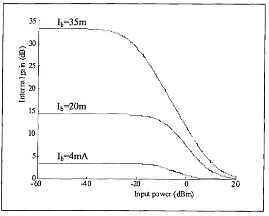
Figure 4.4 The internal gain verses the input power for various bias current h ...54
Figure 5.1 A TOAD switch: (a) schematic block diagram and (b) waveforms...63
Figure 5.2 Diagram of fused fibre coupler...67
Figure 5.3 SLA model... 69
Figure 5.4 Dynamics of carrier density inside the active region of an SLA... 71
Figure 5.5 A schematic of TOAD showing all the electric fields...73
Figure 5.6 Gain response of the TOAD for Tasy = 0...80
Figure 5.7 TOAD normalised switching window (Tasy = 0 )... 81
Figure 5.8 Gain response of the TOAD for Tasy = 3 ps...81
Figure 5.9 TOAD normalised switching window (Tasy = 3 ps)... 82
Figure 5.10 Gcwand Gccwversus time for different values of the control pulse energies.. 86
Figure 5.11 TOAD switching window profiles for different values of control pulse energies86 Figure 5.12 Maximum signal energy against the SLA initial gain G0...88
Figure 5.13 Gain profiles of the TOAD for Tasy =3 ps...90
Figure 5.14 TOAD switching window profile for T„sy =3 ps... 90
Figure 5.15 Gain response of a large asymmetry loop...91
Figure 5.16 Phase response of a large asymmetry loop...91
Figure 5.17 TOAD switching windows with a large asymmetry...92
Figure 5.18 TOAD switching window with a reduced asymmetry...92
Figure 5.19 Width of switching window versus the SLA asymmetry...93
Figure 5.20 TOAD switching window with a width of 10 ns... 94
Figure 5.21 Normalised peak of the TOAD switching window against the SLA bias current for 100 GHz control pulse... 95
Figure 5.22 Basic elements of an all optical router based on TOAD...97
Figure 5.24 Output of TOAD 1 at port 1 (address recognise), also shown is the profile of
the switching window... 100
Figure 5.25 Output of TOAD 1 at port 1 (address recognise) for OTDM packet with
multi-bit address... 101
Figure 5.26 Outputs of the TOAD 2 at 250 Gbit/s data stream (a)output port 1 (b) output
port 2 ...102
Figure 6.1 The transformation from timing jitter noise to relative intensity noise... 105
Figure 6.2 (a) the switching window, (b) the input data stream and (c) the recovered
channel plus the residual and neighbour channel crosstalk...107
Figure 6.3 The relative intensity noise versus the SLA asymmetry forRMSjuter = 1 ps and
different SLA lengths...I l l
Figure 6.4 The relative intensity noise versus the SLA asymmetry forRMSjjtter= 2 ps and
different SLA lengths...112
Figure 6.5 The relative intensity noise versus the SLA asymmetry for signal width of 2 ps
and different SLA length...113
Figure 6.6 The relative intensity noise versus the SLA asymmetry for Go =10 and different
SLA length...114
Figure 6.7 The router residual crosstalk versus the SLA asymmetry for total bit rate of 100
Gb/s for SLA length of 0.1 and 0.5 mm...116
Figure 6.8 The router residual crosstalk versus the SLA asymmetry for total bit rate of 200
Gb/s for SLA length of 0.1 and 0.5 mm...117
Figure 6.9 The router residual crosstalk versus the SLA asymmetry for different values of
the amplifier initial gain... 118
Figure 6.10 The router residual crosstalk versus the SLA asymmetry for different values of
Figure 6.11 The router residual crosstalk versus the SLA asymmetry for different values of
duty cycles... 119
Figure 6.12 The router neighbour channel crosstalk versus the SLA asymmetry for
different length of SLA...120
Figure 6.13 The router neighbour channel crosstalk versus the SLA asymmetry for
different values of duty cycles... 121
Figure 6.14 The router neighbour channel crosstalk versus the SLA asymmetry for
different bit rates... 122
Figure 6.15 The router neighbour channel crosstalk versus the SLA asymmetry for
different values of the amplifier initial gain Go... 123
Figure 6.16 The router neighbour channel and residual crosstalks versus the SLA
asymmetry...124
Figure 6.17 The router crosstalk versus the SLA asymmetry for different SLA length with
total bit rate of 100 Gb/s... 125
Figure 6.18 The router crosstalk versus the SLA asymmetry for different SLA length with
total bit rate of 200 Gb/s... 126
Figure 6.19 The router crosstalk versus the SLA asymmetry for different SLA length with
total bit rate of 300 Gb/s... 126
Figure 6.20 Trade off between the noise and the crosstalk of the router for total bit rate of
100 Gb/s...127
Figure 6.21 Trade off between the noise and the crosstalk of the router for total bit rate of
200 Gb/s...128
Figure 7.1 Block diagram of an OTDM system...132
Figure 7.3 Power penalty versus crosstalk of router for 100 Gb/s OTDM for different
values of Mtdm...142
Figure 7.4 Power penalty versus RINrouter for different values of router crosstalks 143 Figure 8.1 Schematic block diagram of a 1x4 router...146
Figure 8.2 Format of OTDM packets signal... 149
Figure 8.3 Time waveforms of the 1x4 router, (a) input, (b) output port 3, (c) output port 4, (d) output port 5, and (e) corsstalk at the output port 6...150
Figure 8.4 Crosstalk versus signal bit rate for 1x4 and 1x2 routers...153
Figure 8.5 Crosstalk versus control pulse energy... 154
Figure 8.6 2x2 OTDM optical router with input and output buffers...156
Figure 8.7 Operation of 2x2 OTDM router with input/output buffering... 158
Figure 8.8 Waveforms of input and outputs of 2x2 router with input and output buffers. 160 Figure 8.9 2x2 router design using output buffers... 161
Figure 8.10 Optical buffer design... 161
Figure 8.11 Operation of 2x2 OTDM router with output buffering...163
Figure 8.12 2x2 OTDM router with header recognition...164
Figure 8.13 Waveforms of input and outputs of the router with output buffers...165
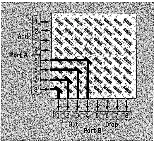
Figure 8.14 8x8 packet switch using a Banyan network architecture...166
Figure 8.15 Three-stage switch using TOADs to identify each address bit... 168
Figure 8.16 Series router configuration...171
Figure 8.17 Parallel router configuration... 173
Figure 8.18 8x8 Banyan network architecture...175
GLOSSARY OF ABBREVIATIONS
ASE Amplified Spontaneous Emission BER Bit Error Rate
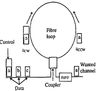
BPF Band Pass Filter CCW Counter Clockwise CW Clockwise
EDFA Erbium-doped Fibre Amplifier FP-SLA Fabry-Perot SLA
FWM Four Wave Mixing FWHM Full Width H alf Maximum I/O Input / Output
MZI Mach-Zender Interferometer NOLM Nonlinear Optical Loop Mirror NLWG Nonlinear Waveguide Switch NXT Neighbour Channel Crosstalk MEMS Micro-Electro-Mechanical Systems OTDM Optical Time Division Multiplexing RIN Relative Intensity Noise
RMS Root-Mean-Square RXT Residual Crosstalk
SLA Semiconductor Laser Amplifier SDH Synchronous Digital Hierarchy SONET Synchronous Optical Network TDM Time Division Multiplexing
TOAD Terahertz Optical Asymmetric Demultiplexer TW-SLA Travelling Wave SLA
GLOSSARY OF SYMBOLS
Symbol Definition
a Gain coefficient o f an SLA
Aejf Effective cross section area o f an SLA
B Electrical bandwidth
B0 Optical bandwidth
c Speed o f light
q Velocity o f photons moving
CXTrouter Router channel crosstalk
d Active area depth o f SLA
E Electric field
Ea Energy gap between conduction bands
Ec Control pulse energy
Eq tr l Optimised control pulse energy for TOAD
Emax Maximum signal energy for TOAD routing for avoiding the perturbation o f the SLA properties
Ep Photon energy
Esat Saturation energy o f an SLA
Esp Spontaneous emission field
E,ot Total energy within the segment / Frequency
fj(j) The discrete probability density function
F Noise figure
F Ccw Gain and phase function o f TOAD in the CCW direction
FCw Gain and phase function o f TOAD in the CW direction g Differential gain o f an SLA
g } and g 2 The degeneracies o f the two energy levels
gp Peak differential gain o f the gain spectrum o f an SLA
Gcw CW gain o f signal pulses in TOAD
Gs Single pass gain
Gss Small signal gian o f an SLA
h Planck’s constant
i l Power spectral density o f the electrical input noise current
Io Light intensity
h Bias current
Ic Electrical current
J Bias current density
k Boltzman constant
K Field coupling factor
L The half o f the length o f the fibre loop
h Loss due to the optical filter
k o p t Loss between amplifier and photodetector Lsla Length o f the SLA
M Number o f packets
Mtdm Number o f OTDM channels
n Refractive index
n0 Refractive index in the absence o f an input signal
nf Refractive index o f the fibre
ftsp Population inversion parameter
N Carrier density
N0 Transparent carrier density
Ni Carrier density without singal applied
Nph Number o f photons per unit energy
N
1 ys-sp signal-spontaneous beat noise spectral density
N
1 ysp-sp spontaneous-spontaneous beat noise spectral density
N* Carrier density o f lasing threshold
P Optical power
Pavg Averaged optical power for the signal
Pin Optical power o f the input signal
PN Noise power o f an SLA
P 0 Peak optical power o f a pulse
Psat Saturation power
Psig Signal power
Psp Spontaneous emitted power
p ,(t) Probability function o f Gaussian shape
p(t) Input data packet power profile
q Electron charge
r Reflectivity o f SLA
r; Reflectivity o f the input facet o f an SLA
r2 Reflectivity o f the output facet o f an SLA
rw Extinction ratio o f switching window
R Responsivity o f the photo-detector
Rb Channel bit rate
Rg Optimal gain ratio between CW and CCW pulses for maximum TOAD switching gain
Rl Load resistance o f the photo-detector
RINdemu Demultiplexer relative intensity noise
RINrouter Router relative intensity noise
RMSjuter RMS timing jitter o f signal pulses
RXTDEmu Demultiplexer residual crosstalk
RXTrouter Router residual crosstalk
T Temperature in Kelvin
Tb Bit duration o f an OTDM time slot
Td Packet duration
Tw Width o f switching window
V Volume
Vg Group velocity
VSl a Volume o f the active medium o f an SLA
w(t) Output signal profile o f the TOAD router
X ct Crosstalk o f multi-ports router
XTt Total crosstalk
z Longitudinal position o f light propagation
e0 Vacuum permittivity
a Loss coefficient
asl a Photon loss coefficient o f an SLA
aief Linewidth enhancement factor
q.2 Optical amplifier beat noise power density between signal and spontaneous
s~sp emission
q2 Optical amplifier beat noise power density between spontaneous emission
sp~sp components
Optical amplifier thermal noise power density
u th
co Optical frequency
p Energy density
T Confinement factor
% Excess noise coefficient o f SLA
y Excess loss o f the coupler
dQ, Solid angle (blackbody radiation theory)
dn/dN Refractive index differential coefficient
AT Separation time between two pulses
X Optical wavelength
X0 Centre wavelength o f input signal
Xp Wavelength o f peak gain
Xs Signal wavelength
AXg Spectral width o f the differential gain o f an SLA
Tc Width o f control pulse
?sig Duration o f the signal bit
Tsp Carrier spontaneous life-time
4
> Optical phase§CfV Phase shift for CW component
fycciv Phase shifts for CCW component
A(j) Phase difference between CW and CCW signal pulses
Random phase for each component o f spontaneous emission
T) Photodiode quantum efficiency
T] DEMUX Switching ratio o f the target pulse energy
Tim Input coupling efficiencies o f the optical amplifier
Chapter 1
Introduction
The growing demand for increased network capacity has generated interest in the
development of ultrafast transparent optical networks (TONs). In these networks, the tardy
opto-electrical (O/E) or electro-optical (E/O) conversions that are inherent in current fibre
network systems are avoided. Consequently, there is a significant reduction in bandwidth
bottlenecks resulting in superior quality of service (QoS). To date most research on optical
networking has concentrated on wavelength division multiplexing (WDM) [1-4], which
routes different packets according to the wavelength of the optical carrier. In WDM
systems, which require high flat gain amplifiers, nonlinearity associated with fibre results in
SNR degration as the number of channel increases, and cross phase modulation limits the
number of the channels. Therefore, optical time-division multiplexing (OTDM) is
considered as an alternative to WDM for future networks, which utilise a single wavelength
for high (> 100 Gbit/s) data rates [4-6]. In OTDM networks many signals are interleaved
before being transmitted using a single wavelength. Each signal from a lower bit-rate
source is broken up into many segments (slots), each having very short duration, and are
multiplexed in a rotating repeating sequence (i.e. round robin fashion) onto a high bit-rate
transmission line. The use of short duration pulses (preferably soliton) allows information
to be transmitted at very high bit rates (>100 Gb/s). An asset of OTDM is its flexibility,
which allows for variation in the number of signals that can be transmitted over a single
bandwidth. It is therefore believed that OTDM networks are excellent candidates for
meeting the future ultrafast network requirements [7-8]. It is not envisaged as a replacement
but complementary to the WDM, where the major traffic at the backbone to be carried by
OTDM.
Practical resolution of OTDM system is a challenge and costly task facing researchers and
service providers. Many technologies have been proposed, including ultrashort optical
pulse generation, time division multiplexing, optical repeaters, synchronisation, time
domain demultiplexing and so on, which may be used to set up an all optical OTDM
network. The key element for OTDM networks would be all-optical routers, which are
capable of switching signal in the optical domain, thus overcoming the bottleneck of
optoelectronic conversion process. Therefore, particular attention has to be paid to all
optical routers. A few types of all optical routers have been developed by researchers [38-
42]. Here we investigate all optical router based on the terahertz optical asymmetric
demultiplexer (TOAD) by developing a mathematical model.
1.1 Organisation of Thesis
The thesis is divided into nine chapters. Following the introduction, a technical and
historical review for optical communication systems is given in Chapter 2. This chapter
begins by introducing optical communication history. And then goes on to describe TDM,
WDM and OTDM systems. The challenges and trends of optical communication systems
Chapter 3 presents a review of current technologies for the switching of signals in the
optical domain. Switchers are characterised by the switching time, repetition rate, control
pulse energy, and practicality. Summary of the key device criteria for the all-optical
switches shows that the most likely candidate for an optical router is TOAD, which has
been investigated in this work.
One of objectives of this project is to develop a model of an all optical router based on the
terahertz optical asymmetric demultiplexer (TOAD). The operation of TOAD is based on
the nonlinear properties of semiconductor laser amplifier (SLA). Thus the theoretical
background of SLA is introduced in Chapter 4. This chapter presents SLAs with the
accompanying equations that describe the characteristics of the device under continuous
wave input. The concept of noise of SLA and how it originates from amplified spontaneous
emission are described and its contribution to receiver generated noise is shown with the
introduction of noise equations.
In Chapter 5, a new mathematical model for all optical router is presented. The model
architecture is based on a system, which has as its input an OTDM packet containing
header and payload information. The model numerically simulates the extraction of the
header information from the incoming OTDM packet using a single TOAD, which is
subsequently used to make a routing decision for the packet payload. The payload
information is routed through a second TOAD according to the information contained in
the header.
Based on this mathematical model, a comprehensive noise and crosstalk analysis of the all
amplitude of the switching transmission window together with the simulation performance
namely the bit error rate (BER) is also presented in this chapter. After describing the origins
of the noise and crosstalk associated with an all-optical router, the simulation results of the
noise and crosstalk are presented and analysed.
Chapter 7 presents bit-error-rate performances of the router. This chapter begins by
presenting the system model of the receiver and signal to noise ratio (SNR). All the noise
courses including those related to the router such as: (i) The channel crosstalk originating
from the leakage of non-target channels and (ii) the relative intensity noise induced by the
timing jitter in router are discussed and expressed mathematically. A comprehensive
expression for the BER is presented and results for the BER for different data rates with
/without router compared with the base line are given. The compact of the crosstalk and the
relative intensity noise of the router on the optical power penalty for 100 Gbps OTDM are
also investigated.
Chapter 8 investigates novel all optical routers with multi-input and output, say 1x4, 2x2
routers. In this chapter, 1x4 router that uses TOADs as the routing element is described in
detail by means of mathematical modelling. The mathematically model developed is used
to investigate performance of the 1x4 router. The results presented are compared with 1x2
router. The chapter goes on to discuss the operation of the 2x2 routers based on TOADs
with input and output buffers. Using the mathematical model developed for 1x2 router, the
2x2 router is simulated and results are shown at various stages. Finally the multiports router
based on Banyan network is introduced, where the 2x2 switches could be based on TOAD.
The OTDM packet address bit is modified to include “A” address bits. A novel N bit
for the crosstalk for the series and parallel multiports router configuration is given. Results
for a particular case study is presented.
Finally, conclusions and suggestions of further works are discussed in Chapter 9.
1.2 Aims and Objectives
The fundamental aim of the work presented in this thesis is to design and develop a novel
all optical router based on TOAD for LANs/MANs and identify the system requirements
and physical specifications for the proposed devices. In order to achieve these, a number of
research objectives have been identified, as outlined below:
❖ Design and simulate a novel all optical router in high-speed communication systems.
❖ Develop model to investigate novel architectures for OTDM packet switching networks.
❖ Investigate characteristics of the all optical router against various system parameters such as: packet format, node size, bit-rate, type of switching network, node routing architecture, and choice of ultrafast demultiplexer.
❖ Identify the advantages and drawbacks of the proposed network model, compare it to the existing network models and further modify model.
1.3 Original Contributions
During the course of this work, the following original contributions have been made:
♦♦♦ Development of a new analytical model for calculating the width of all optical router switching window. (Section 5.2)
♦> Optimisation of the all-optical router parameters for maximising peak transmission of the all optical router switching window. (Section 5.3)
❖ Optimisation of the switching energy of all optical router for maximising the peak transmission of switching window. (Section 5.3.4)
❖ Analysis of relative intensity noise, residual crosstalk and neighbour channel crosstalk in all optical router. (Section 6.2)
❖ Bit-error-rate comparisons of with and without all optical router for 100 Gb/s bit rate. (Section 7.4)
❖ Optimisation of the device parameters for all optical router for minimising the power penalty at different bit rate (100 Gb/s -300Gb/s). (Section 7.4)
❖ Development of a new model of 1x4 and 2x2 all optical routers based on TOADs. (Sections 8.2 and 8.3)
♦♦♦ Analysis of relative intensity noise, residual crosstalk and neighbour channel crosstalk of all optical router in the Banyan network. (Section 8.5.3)
1.4 Publications
The work presented in this thesis has resulted in the following publications, which are listed in chronological order.
R. Gao, Z. Ghassemlooy, G. Swift, and P. Ball, "Simulation of all optical time division multiplexed router", Proceedings o f Photonics West 2001, 4292, pp.214-223, Jan. 2001.
R. Gao, A. Als, Z. Ghassemlooy, G. Swift, and P. Ball, "Simulated Error Performance of An All Optical Time Division multiplexed system", Proceedings o f the Convergence o f Telecommunications, Networking & Broadcasting 2001, pp. 171-176, Liverpool, UK, June 2001.
R. Gao, Z. Ghassemlooy, G. Swift, and P. Ball, "Performance analysis of all optical time division multiplexed router based on terahertz optical asymmetric demultiplexer", Proceedings o f SPIE Asia-Pacific Optical and Wireless Communications 2001, 4582, pp. 152-158, November 2001.
R. Gao, Z. Ghassemlooy, and P. Ball, “BER Analysis of Packet Based High-Speed OTDM System Employing All Optical Router ", Proceedings o f 7th European Conference on Networks & Optical Communications, 4292, pp.214-223, June, 2002.
R. Gao, Z. Ghassemlooy, and P. Ball, “BER Analysis of Packet Based High-Speed OTDM System Employing All Optical Router ", accepted by the Microwave & Optical Technology Journal, 2003.
Chapter2
Literature Review and Survey:
TDM, WDM and OTDM
2.1 Introduction to Optical Communications
Light has been used for communicating information since signal fires were used to send
messages. Manually operated signal lanterns on ship and signal flares are other examples of
early optical communication systems. A revolution in optical communication occurred in
1880 when Alexander Graham Bell reported the modulation of sunlight with the sound of a
bell for speech transmission over a distance of 200 m [9]. From the late 1880’s to the early
1960’s low capacity short range links represented the state-of-the-art in optical
communication. For atmospheric communication, light was really only practical for line of
sight, short distance transmission, since scattering and weather conditions proved to be an
obstacle for the optical signal. To overcome some of these problems, dielectric
waveguiding which has a history dating back to 1910 Hondros [10] was used to confine the
optical signal. In 1950 B. Brian Sr. at American Optical was developing optical fibre
bundles for light transmission. Some significant milestones in optical communication
include: the invention of the laser in the 1960’s, the development of low loss optical fibre in
development of practical amplifiers by the 1990’s. Collectively these paved the way for a
concerted effect into the development of practical optical communication systems.
In particular the development of low loss optical fibre allowed significant advances to be
made in fibre communication with Kao [11] predicating that 20 dB/km loss was achievable
in glass fibres by removing the impurities. At this level, optical fibre communication was
becoming a viable alternative. Prior to this the losses were in the 1000 dB/km range
(coaxial cables which guide electromagnetic waves exhibit losses between 5 and 10
dB/km). Research continued on optical fibres and by 1977 the fibre losses were reported to
be as low as 0.5 dB/km for 1200 nm wavelengths.
Nowadays, optical fibre is a exceedingly low-loss propagation medium. Losses can
approach 0.15 dB/km and, with modest amounts of optical amplification, multi-Gbps data
streams can be transmitted over tens of thousands of kilometres without electronic
regeneration. Conventional electronic systems only give an order of magnitude less
transport capacity. In comparison, convention coaxial cables will lose half the electrical
power in just a few hundred meters whilst a good quality optical fibre loses half of the i
optical power in the propagating field in 15-20 km. In addition to significantly lower loss,
packaging and volume benefits are also a feature. Low-loss coaxial cables often have
diameters of a centimetre or more. Consideration of the cross-section area is particularly
significant when fibres are used in crowded conduits.
In parallel with the development of fibre systems, work continued on the various
components needed to complete the optical communication system [12-15].
lasers, which were compatible in size with the optical fibre system, were becoming
widespread. LEDs operate at much lower current than injection lasers, but their mechanism
of light generation is by spontaneous emission and consequently the optical output of an
LED is of random phase with no coherence. The injection laser on the other hand uses
stimulated emission in a resonant cavity providing a coherent light source. The spectral
width of an LED is also much wider than the laser. For 800-850 nm wavelength operation
GaAlAs devices have spectral widths in the range 30-60 nm and 1-2 nm for LEDs and
lasers respectively. However the LED does offer certain advantages over the laser, e.g.
lower cost, ease of manufacture, reliability, and it gives a linear light output current curve.
The first semiconductor lasers were fabricated from alloys of gallium arsenide which
emitted in the range 0.8-0.9 /mi. The range of emission was extended to 1.1 to 1.5 /mi,
taking advantage of improved fibre characteristics. The laser and LED are now becoming
well established with a lifetime improvement from a few hours up to 25 years for
semiconductor lasers and 100 years for LED’s.
The most common wavelengths used for optical communications fall between 0.83 and
1.55 microns. Other wavelengths can also be used but this range encompassed the most
popular applications. A wavelength of 1 micron corresponds to a frequency of 300 THz
(300,000 GHz), which is considerable higher than those associated with conventional radio,
microwave, or millimetre-wave communication systems. A high centre frequency implies
that extremely high modulation bandwidths should, in principle, be possible. A one-percent
bandwidth is easily achieved for optical carriers, which is far greater modulation bandwidth
than a microwave carrier can provide. Although wide bandwidth is important, it is not only
changes in communication. To gain a broader understanding, we need to examine the
advantages light has in both guided and unguided modes of transmission.
Traditional communication techniques based on electronics are now being challenged by
these new optical systems [16-20].
The research and development into fibre communication systems is driven by the promise
of communication systems offering numerous advantages such as small physical size, low
costs and high interference immunity. In the past several years, lightwave systems have
been demonstrated with increasingly higher bit rates. Electrical TDM system has achieved
a bit rate of 40 Gbit/s [21], whilst a wavelength-division-multiplexed system with sixteen
different wavelength channels has been demonstrated operated at 640 Gbit/s [22].
Significantly an optical time division multiplexed system has been shown to have an
aggregate rate of 250 Gbit/s at single wavelength [23]. Aggregate bit rates achieved for
laboratory system for TDM, WDM and OTDM are shown in Figure 2.1.
700
600
500
S 400 OQ)
2 300 m
200
100
0
1988 1990 1992 1994 1996 1998 2000 2002
year
Figure 2.1 Demonstrated aggregate bit rates for TDM, WDM and OTDM laboratory lightwave systems
-1 1 1 1
---TDM ... WDM
--- OTDM at single wavelength /
/
_ —
/ / #/
/ *
In respect of composite optical communication systems the point to point system is now
well established, and is the most common configuration used for optical communications. It
is now possible for such optical fibre systems to cross oceans and continents, while free-
space systems provide high data-rate communication links between satellites at
geosynchronous distance. Optical communications, in combination with microwave and
wireless technologies, are enabling the construction of high-capacity networks with global
connectivity.
In current optical communication systems, any processing of the signal is performed
electronically following by an optical to electronic conversion, the electronic signal is then
to be converted back to the optical domain. This creates a bottleneck for future networks
proving date rates up to 100 Gbit/s. The bottleneck significantly reduces the speed of
transmission in addition to the relatively slow electrical switching rates. The speed
limitation of electronic switching is currently limited to about 10 Gbit/s [24]. To meet the
requirement of future broadband multimedia services, which is likely to require speeds of
the order of 100 Gbit/s [25], the all optical communication network is a solution, which can
transmit information at very high bit rates (>100 Gbit/s).
A number of consortiums are actively working on areas of high-speed communications, e.g.
*♦♦ The PHOTON project (Physical-Layer High-Speed Optoelectronics for Tomorrow's
Optical Networks), funded by the Engineering and Physical Sciences Research Council
the optical networking into the premises, access layer and metro layer of a network.
This project is a collaboration between a large number of UK universities and industry.
❖ At the University of Cambridge hardware based research is being carried out so that
current networking systems such as Gigabit Ethernet can progress to Terabit Ethernet
[26, 27].
❖ Another project called OPSnet project researches optical packet switching, in particular
building upon the results obtained from the earlier EPSRC project WASPNET, which
demonstrated a prototype switch within a network environment. As many of the
networking issues facing the development of an optical backbone layer have come into
focus during the past year, a clearer idea of the functions and performance needed from
optical packet switching are starting to emerge. For example new technologies and
technical approaches are required to enable operation at 40 Gb/s, with scalability to
>100 Gb/s. The networking issues associated with the integration of the optical
backbone layer and the IP layer require effective solutions. In this project, fundamental
asynchronous packet operation has been made, which have major impacts on the
hardware solutions. The outcomes from the design and test of an all-optical packet
switched node, enabled the major key issues for realistic packet networks to be
understood; the OPSnet project seeks to answer a number of these. Expected outcomes
are therefore concerned with understanding:
♦ The relative merits of asynchronous and synchronous packet operation, and the
impact of asynchronous operation on switch and network performance.
♦ The impact of data traffic statistics on switch design.
A network demonstrator supporting an end-to-end connection across the electronic and
optical domains will support these activities.
❖ A study into the development of European network linking major centres in Europe is “
COST 239: Ultra-High Capacity Optical Transmission Networks”. The findings of this
study in terms of data requirements of European cities are summarised in Table 2.1.
Table 2.1 Typical data requirements of European cities
Cities Data rate (Gbit/s)
London-Paris 150
Paris-Madrid 120
Zurich-Milan 90
Milan-Rome 120
Prague-Berlin 90
Berlin-Moscow 90
2.2 Lightwave Systems
2.2.1 Time division multiplexing network
Time-division multiplexing (TDM) is a well-known technique that has been widely used
as shown in Figure 2.2, a number of nodes, say N, share a common broadcast channel (i.e.,
the transmission medium) in the round-robin fashion. Sharing is usually equal, i.e., when a
node’s turn comes up, it transmits for T units of time before relinquishing the channel.
(However, unequal sharing can be affected by having node i transit for k(T time units,
where i= 1,2,..., N, and the k\ are arbitrary integers that are known to all the nodes.)
Si
TDM Link
Sn
Figure 2.2 A TDM link and multiplexer
Nodes in a TDM system must also be perfectly synchronised, so that nodal transmissions
do not collide with one another (as in a random, multiaccess communication network), and
they do not “spill over” into their adjacent nodes’ transmission windows. In a synchronous
TDM system, a node gets its allotted time even if it is idle. Thus, time in such a
synchronous TDM channel consists of a sequence of equal-sized, nonoverlapping frames,
with each node getting exactly one turn to transmit a frame. (Such a frame is also referred
to as a cycle, period, or a TDM frame in the literature.) Also, note that two consecutive
transmission instants at any node are separated by exactly one frame length.
Frame synchronisation is implemented with the beginning of each frame being marked by a
transmission instant in a frame and its transmission duration are known to all nodes, a nodal
transmitter need not identify itself explicitly—this information is implicit. For a point-to-
point TDM link as shown in Figure 2.2, the TDM multiplexer provides this synchronisation
information, while in a distributed, broadcast, multiaccess TDMA network, the
synchronisation bits may be transmitted by any designated node, which is generally the one
that is the first transmitted data in a frame.
An asynchronous TDM system, on the other hand, does not waste any time on idle nodes.
Thus, while all nodes are still scanned in round-robin fashion, only the active nodes
transmit on the channel, consequently, the frame lengths are not fixed any longer, and a
nodal transmitting must also identify itself explicitly in its transmission, thereby increasing
the amount of overhead information per frame.
Trade-offs to be considered when designing or comparing a synchronous to an
asynchronous TDM system include simplicity of design or operation, channel utilisation
(and, hence, access delay), and amount of overhead.
Network architectures have been proposed [12] that employ switches such that a TDM
packet be routed all optically from one of the incoming fibre ports of a switch to its desired
output port. There is generally no notion of a synchronous TDM frame on any link, so
according to our above classification, this is an asynchronous TDM system. Frequently,
2.2.2 Wavelength division multiplexing network
2.2.2.1 WDM network
Data out Fibre Fibre
Data in
Transmission system Optical
Transmitters Multiplexer
WDM WDM
Demultiplexer ReceiversOptical
Figure 2.3 Optical WDM system block diagram
Wavelength-division multiplexing (WDM) is an approach that can be used to exploit the
huge opto-electronic bandwidth. Here end-user’s equipments generate data at electronic
rates, which are then used to modulate multiple WDM channels. A number of end users
may be multiplexed onto the same fibre as shown in Figure 2.3. Using WDM, the usable
optical spectrum [32] (see Figure 2.4) is apportioned into a number of non-overlapping
wavelength (or frequency) bands, with each wavelength supporting a signal communication
channel operating at whatever rate one desires, e.g., peak electronic speed. The
corresponding challenges for this technology at the moment are the design and
development of appropriate network architectures, protocols and algorithms to support the
various networking functions. At the moment WDM devices are easier to implement since,
result, several WDM devices are available in the marketplace today, and more are
emerging.
L O S S
H S O T H z d B /k m
U S A B L E BA N D W ID TH
2 0 0 n m 2 0 0 n m
2.0
1.0
1600 1800
1400 1200
800
[image:42.612.153.414.98.300.2]W A V E L E N Q T H (n m )
Figure 2.4 The low attenuation regions of an optical fibre
Research and development on optical WDM networks have matured considerably over the
past few years, and they seem to have suddenly taken on an explosive form, as evidenced
by recent publications [28] as well as overwhelming attendance and enthusiasm at the
WDM workshops during recent conferences: E.g. the optical fibre communication
(OFC’2002) conference and the IEEE International Conference on Communications
(ICC’2002). A number of experimental prototypes have been developed and are currently
being deployed and tested mainly by telecommunication providers in the U.S., Europe, and
Japan. With the rapid emergence of WDM, it is anticipated that the next generation of
Internet will employ WDM based optical backbones.
Current activities indicate that some sort of WDM network will be deployed mainly as a
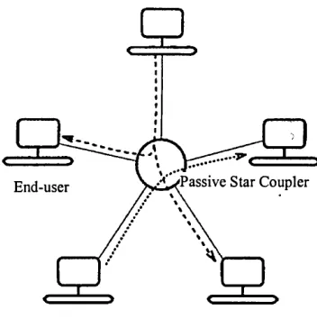
shows a passive-star-based optical WDM network [32]. An end-user sends its transmission
to the passive star on one wavelength. The information streams from multiple sources are
optically combined by the star and the signal power of each stream is equally split and
forwarded to all of end-users on their receiving fibres. An end-user’s receiver is turned to
only one of the wavelengths, hence it can receive the information stream. End-users, for
whom the architecture and operation of the backbone will be transparent except for
significantly improved response times, will attach to the network through a wavelength-
sensitive switching/routing node. An end-user in this context need not necessarily be a
terminal equipment, but the aggregate activity from a collection of terminals include those
that may possibly be feeding in from other regional and/or local subnetworks. So that the
end-user’s aggregate activity on any of its transmitters is close to the peak electronic
transmission rate.
[image:43.612.186.362.370.552.2]'Passive Star Coupler End-user
Figure 2.5 A passive-star-based local optical WDM network
2.2.2.2 limitation with WDM used in networks
End-users in a WDM based backbone network may communicate with one other via all
fibre links, e.g., to provide a “circuit- switched” interconnection between two nodes, which
may have a heavy traffic flow between them and which may be located “far” from each
other in the physical fibre network topology. Each intermediate node in the lightpath
essentially provides an all-optical bypass facility to support the lightpath.
In an N-node network, if each node is equipped with N-l transceivers [transmitters (lasers)
and receivers (filters)] and if there are enough wavelengths on all fibre links, then every
node pair could be connected by an all optical lightpath, and there is no networking
problem to solve. However, it is important that the network size N should be scalable.
Transceivers technological constraints dictate that the number of WDM channels that can
be supported in a fibre are limited to W (whose value is a few tens today, but is expected to
improved with time and technological breakthroughs). Thus, only a limited number of
lightpaths may be set up the network.
Under such a network setting, for a given set of lightpaths and a constraint on the number
of wavelengths, the challenging problems are how to determine the routes over which these
lightpaths could be set up and the wavelengths that should be assigned to these lightpaths,
so that the maximum number of lightpaths may be established. Although the shortest-path
route may be the most preferable option, this choice may not be adopted on occasions
where there is a need for a large number of lightpaths. Thus, one may allow establishment
of several alternate routes for lightpaths within the network. In such networks the lightpath
probability of blocking is a problem, which requires network optimisation.
In this regard, note that, normally, a lightpath operates on the same wavelength across all
wavelength-continuity constraint. Thus, two lightpaths that share a common fibre link should not be
assigned the same wavelength. However, if a switching /routing node is also equipped with
a wavelength converter, then the wavelength-continuity constraints disappear, and a
lightpath may be switched between different wavelengths on its route from its origin to its
destination.
This particular problem is referred to as the routing and wavelength assignment (RWA)
problem. Returning to the networking problem, the designers of the next generation
lightwave networks need to be aware of the properties and limitations of optical fibre and
devices available in order for their corresponding protocols and algorithms to take
advantage of the full potential of the WDM. Often a network designer may approach the
WDM architectures and protocols from an overly simplified, ideal, or traditional-
networking point of view. Unfortunately, this may lead an individual to make unrealistic
assumptions about the properties of fibre and optical components, and hence may result in
an unrealisable or impractical design.
2.2.3 OTDM networks
Electrical signals
Fibre
Fibre Light
Source Router
eN
External OTDM Modulators Multiplexer
OTDM
Derrult ip lexer R eceiverOptical
Optical time division multiplexing system networks are considered as alternative to the
WDM for future all optical networks. That utilises a single wavelength for high
(>100Gbit/s) data rates. A block diagram of a typical OTDM transmission system is shown
in Figure 2.6. Instead of WDM, the nodes in Figure 2.6 use a synchronous TDM system for
multiaccess communication to implement a local optical TDMA network. The access
method at the nodes can be implemented in one of two ways: (1) multiplexing the data from
the sources using bit-interleaving or (2) multiplexing based on time slots, each of which can
obtain several bits. However, regardless of the above choice, the physical-layer bit rate of
the TDMA network would need to be enhanced to N times the data rate of an individual
node, where N represents the number of nodes in the networks. In other words, if the user
data rate is r bps, the network transmission medium must support a data transmission rate
of Nr bps over the entire network span. Thus, in an OTDM based network, if individual
nodes have outbound electrical data stream at 10 Gbps with 10 such nodes connected to the
network, then each node should be able to transmit at a rate of 100 Gbps on the optical fibre
together with the global synchronisation with the other nodes in the network. This is indeed
a nontrivial task as opto-electronic interfaces would find it difficult to support the ultra-high
transmission rates together with the requirement to preserve the optical pulse shapes against
fibre dispersion and timing jitter.
Implementation of the functional units that would constitute an OTDM network requires
special considerations to be capable of handling the ultrafast optical signal. These
components must be capable of generating narrow optical pulses at high repetition rates and
be able to multiplex and demultiplex with complete timing synchronisation [29,30]. In
fibre spans [31], and possible processing of the optical signals at network nodes using
optical buffers and other processing elements [33, 35-37].
In the following subsections, the salient features and operating principles of the basic
subsystems in OTDM networks are described.
❖ optical sources (OTDM signal)
❖ modulation and multiplexing
❖ demultiplexing and clock recovery
❖ optical TDM network architectures and proposals
2.2.3.1 OTDM signal
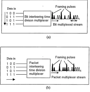
Two types of OTDM signal are illustrated in Figure 2.7. Optical signals representing data
streams from multiple sources are interleaved in time to produce a single data stream. The
interleaving can be implemented at the bit level as shown in Figure 2.7(a). Alternatively if
the data is sent in the form of packets, it can be accomplished at the packet level as shown
in Figure 2.7 (b). If the packets are of fixed length, the recognition of packet boundaries is
much simpler. In the following description, it is assumed that fixed-length packets are used.
For both bit and packet interleaving, a framing pulse must be used. In the packet
interleaving framing pulses mark the boundary between packets. In bit interleaving, if n
input data streams are to be multiplexed, then a framing pulse is used every n bits. As will
be seen later, these framing pulses are useful for demultiplexing of individual packets from
Framing pulses Data in
Bit interleaving time
divison multiplexer > • *
Bit multiplexed stream
(a)
Framing pulses Data in
Packet interleaving time division multiplexer
[image:48.612.129.430.63.369.2]Packet multiplexer stream
Figure 2.7 OTDM signal generation (a) Bit interleaving, and (b) Packet interleaving
As shown in Figure 2.7, pulses-much shorter than the bit period must be used in OTDM
systems. Ultra short pulses with widths of the order of a few ps can be generated using
mode-locked lasers. As the pulse widths are narrow, their spectral width will be large, pulse
broadening due to the chromatic dispersion is a problem that needs considering when
transmitting over a long span.
2.2.3.2 multiplexing and demultiplexing
At the inputs to the network, lower speed data streams are multiplexed optically into a
extracted from the higher-speed stream optically by means of a demultiplexing function.
Functionally, optical TDM is identical to electronic TDM. The only difference is that the
multiplexing and demultiplexing operations are performed in the optical domain at high
speeds.
Gating signal
Input data
A2 A1
C2 B2 A2 A1
Optical coupler
B2 B1 > - OTDM signal
C2
[image:49.612.104.484.146.408.2]Optical gates
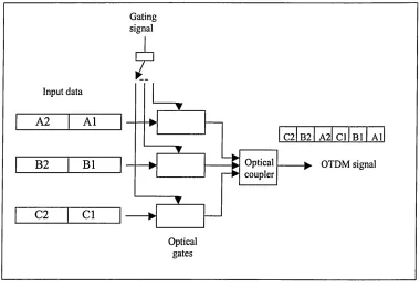
Figure 2.8 Basic elements of an optical time division multiplexer (OTDM).
In OTDM system, data bits for a particular channel, or data packets are allocated a
particular time slot, as shown in Figure 2.8. Input channels are optically multiplexed by
optically gating each input channel once every bit period.
At the receiver the signals can be demultiplexed using a gating procedure as shown in
Figure 2.9, The optical gate could be an electro-absorption modulator or a terahertz optical
Packet interleaved (Compressed) OTDM data
1 2 3 4
nn
Conliol . e ....Splitter
siannl Output
1 i 1 1 11
— * m t ~
!-A --- 4 --- 1 m m
" > 2
---(_A --- j ' --- ---
:---, 4
,JU
j r► . j
---1— A— i
---;---* * “
. A , _ J u j r --- 4---1
---* m r
k - L m
1 --- :--- 1---t M
---- > j 4
i J
■■ ---►
[image:50.612.133.474.51.311.2]AND gate
Figure 2.9 An optical demultiplexer to extract one channel from a packet- interleaved OTDM data stream
The demultiplexing operation can be achieved, in principle, by passing the OTDM bit
stream or packet compressed OTDM signal through a set of AND gates, to convert the
single (serial) high-speed data stream into multiple (parallel) lower-speed data streams that
can then be processed electronically [32]. Demultiplexing of a packet interleaved OTDM is
illustrated in Figure 2.9. Here, a bank of five AND gates is used to break up an incoming
high-speed OTDM packet stream into five parallel streams each with five times the pulse
spacing of the multiplexed streams. The procedure is identical to what would be used to
receive five bit-interleaved stream. One input to each AND gate is the incoming data
stream, and the other input is a control pulse stream where the pulses are spaced five times
apart. The control pulse streams to each AND gate are appropriately offset from each other
portion of the packet, for example, the packet header. This is useful in switch-based
networks for optical routing of packets at intermediate nodes in the networks, and will be
explored further in Section 5.4.2.
The logical AND operation shown in Figures 2.8 and 2.9 is performed optically at very
high speed. A number of mechanisms have been devised for this purpose. Note that the
logical AND operation between two inputs is that one input is the data signal and the other
is the control signal.
2.3 Optical TDM Network Architectures and Proposals
In common with WDM networks, OTDM networks can also be implemented using a
broadcast topology or more dynamically using optical switching. In the case of a broadcast
OTDM network, the topology used is usually a star or a bus. Photonic packet switching
networks that incorporate photonic switching and routing will be referred to as switch-
based networks.
In broadcast networks there is no routing or switching within the network. Switching
occurs only at the periphery of the network by means of tuneable transmitters and receivers.
Note that tuneability in the case of TDM networks refers to the ability to select one of
several time-multiplexed streams. E.g. for a bit-interleaved multiplexed signal, a tuneable
receiver, in a particular tuning state, will be able to receive a fixed time slot in a frame. The
switch-based networks perform routing and switching functions optically within the
photonic packet-switching networks is to provide packet-switched service at rates that are
outside the capabilities of electronic packet-switched networks. The tradeoff between
broadcast and switch-based photonic packet-switching OTDM networks are similar to those
of WDM networks. The broadcast networks suffer from large splitting losses, and are not
practically scalable. They are generally only suitable for LAN applications. The switch-
Chapter 3
All Optical Switches
3.1 Introduction
The speed and bandwidth of the world's fast-growing fibre optic communications networks
and of the Internet are limited by the speed constraints of the electronic switches required to
properly identify and route signals and information packets. Switching light in the light
domain eliminates these "bottlenecks". In the emerging