Abstract— In this paper, perfect trajectory tracking of a non-holonomic Wheeled Mobile Robot (WMR) is developed. The Feedback Linearization (FL) methods may be used to make convergence of WMRs on desired position, and orientation trajectories. Due to the weak performances against exogenous signals, the FL controller is replaced by a Sliding Mode Controller (SMC). Using the SMC with a saturation term may not remove the high range chattering; therefore, a Mamdani-type Fuzzy Sliding Mode Controller (FSMC) is proposed to decrease the chattering effects. The superiority of the proposed pure and fuzzy SMCs to the recent FL method has been revealed through simulations.
Index Terms—fuzzy, sliding mode controller, trajectory tracking, wheeled mobile robot
I. INTRODUCTION
heeled Mobile Robots (WMRs) play important tasks in shopping centers, hospitals and other industrial areas such as transportation, inspection, welding, painting, gluing, drawing and etc [1]. Due to increasing importance of WMRs in industry, they have been investigated by many authors in various applications. Most of the WMR controller systems in literature have been designed to a simple kind of mobile robots, whose center of mass is assumed coincide with the center of rotation. Therefore, most of the recent controllers may not be employed for industrial WMRs, which the robot’s center of mass is not placed on the center of rotation between two driving wheels. This paper is dealing with perfect trajectory tracking of mobile robots in which the center of mass doesn’t coincide with the center of rotation. So a more general kind of WMRs is considered to widen the applications [2].
Because of the nonlinear dynamics and non-holonomic constraints of the WMRs’ kinematics, the controller design is a difficult problem and there is not any routine methodology to solve this problem. Kinematic models of non-holonomic systems may be used as the base of path-following feedback controllers. The models that include dynamic effects are required for other purposes, for instance, using torques as control inputs.
In this paper a computed torque control is developed on the basis of the Feedback Linearization (FL) method.
Manuscript received Jan. 12, 2011; accepted Jan. 19, 2011.
Jafar Keighobadi is with the Faculty of Mechanical Engineering, University of Tabriz, Tabriz, 5166614766 Iran (phone/fax: +98-(0)411-3354153; e-mail: [email protected]).
Yaser Mohamadi was with the Faculty of Mechanical Engineering, University of Tabriz, Tabriz, 5166614766 Iran (e-mail: [email protected]).
However, this method is practical only when the dynamics of the robot is well known. In addition to the complexity of FL methods, the controller’s performance is highly limited due to persistent excitation condition, parameter uncertainties, external disturbances, measurement noises, and other inconsistencies affecting a real system. Furthermore, even if a nonlinear controller can be designed accurately based on the mathematical model, the controller may be too complicated to be implemented with software [2].
Robust sliding mode techniques have been considered recently to improve the performance of the nonlinear controllers [3], [4]. An ideal Sliding Mode Controller (SMC) using the PID sliding surface, provides system dynamics with an invariance property to uncertainties when the system dynamics is controlled. The SMC is robust with respect to uncertainties in the system and external disturbances [5]. However, this control methodology produces some drawbacks associated with a large control chattering. Most of these drawbacks have been tackled by many researchers through integration with different techniques in recent years [6]. One option to deal with high range of chattering has been introduced as using the saturation function as an alternative to the sign function in SMC. This can reduce the chattering limit but it cannot completely remove this phenomena.
It is well known that the fuzzy set theory is arisen from the desire of linguistic description for complex systems and can be used to formulate and translate the human experience to an appropriately automatic control strategy [7]. Fuzzy logic, first proposed by Zadeh, has proven to be a strong tool for controlling nonlinear systems, [8], [9]. In this paper, using the knowledge and experiences of expert engineers, a Mamdani type Fuzzy SMC (FSMC) is proposed to make perfect tracking of position, orientation and velocity trajectories. Due to using triangular membership functions, a simple and robust controller against both uncertainties and exogenous disturbances is developed. Therefore, the chattering phenomenon has been decreased and the WMR path tracking performance has been improved significantly. Due to the simple structure of the fuzzy controller, it may be implemented in real WMR systems which perform various tasks in industry.
The rest of the paper is organized as follows. Section II describes dynamical modeling of WMR. Section III presents FL and sliding mode controllers. In section IV, FSMC is proposed. The performances of developed controllers are evaluated by simulation in section V. Section VI is devoted to discuss simulation result and concluding remarks.
Fuzzy Sliding Mode Control of
a Non-Holonomic Wheeled Mobile Robot
Jafar Keighobadi, Yaser Mohamadi
II. DYNAMICAL MODELING
The kinematic model of the WMR is shown in Fig. 1. The generalized coordinates are: X Y, the Cartesian coordinates of the center of mass of the WMR; the robot orientation with respect to the axis X ; and x, y the relative coordinates along the body axes of the WMR.
The distance between two driving wheels along the body x-axis is 2b. The considered distance between the centers of rotation and mass of the WMR, a leads to enlargement of the application range of the proposed methods to industrial, service and entertainment robots.
The simple model of the nonholonomic WMR shows that the rear wheels are fixed parallel to the body and allowed to roll or spin but not slip. The WMR possesses a single universal wheel which is not a driving one and it is not included in the kinematic model. Kinematic equations of the WMR with respect to the center of mass are given as [2]:
sin cos cos sin 0 1 X a v Y a (1)
= /y a
(2) vx (3) where, v and
are the linear forward velocity of the WMR and its angular velocity around the vertical axis, respectively. The dynamics of the WMR has been obtained in the form of:( ) ( , )
TM q q V q q Cq D (4) where, TR2 represents the input torque vector to the driving wheels; the inertia matrix, M and the vector of centrifugal and coriolis torque, V are functions of the state vector q[X Y ]t in which the superscript t denotes the
transpose of a vector/ matrix; C and D are respectively, the dynamic friction coefficient and unknown but bounded noise/disturbance vector.
The elements of M q( ) and V q q( , ) are given as [1]:
I M R)sin
R ( cos ) I la R I aR l l R a M ( m z 2 1 2 2
11
(5)
I MR)cos
R ( sin ) I la R I aR l l R a M ( m z 2 1 2 2
12
(6)
I MR)sin
R ( cos ) I la R I aR l l MaR ( m z 2 1 2 2
21 (7)
I M R)cos
R ( sin ) I la R I aR l l MaR ( m z 2 1 2 2
22 (8)
1
2 1
( )( sin cos ) (
2 2
)( cos sin ) ( cos sin )
2 2
( cos sin )( sin cos )
2
z
MaR l R
v I I X Y I
l aR la R
R R
M X Y M X Y
a R
M X Y X Y
l (9) 2 2 1
( )( sin cos ) (
2 2
)( cos sin ) ( cos sin )
2 2
( cos sin )( sin cos )
2
z
MaR l R
v I I X Y I
l aR la R
R R
M X Y M X Y
a R
M X Y X Y
[image:2.595.311.510.52.227.2]l (10)
Fig 1. The schematics of WMR
III. SLIDING MODE CONTROLLER
Considering the dynamic model (4) not affected by noise/disturbance input D, the feedback Linearization control law is developed as:
( ) ( , )
T M q U V q q Cq (11) t
[ d, d] p d
U X Y k ek e (12) ( ) d( ) ( )
e t q t q t (13) The subscript d denotes the desired values of , which are the components of vector . The convergence rate of tracking errors
e
ande
to zero may be adjusted with respect to the control gains kd and kp. It has been shownby [2] that the FL control systems are sensitive to the exogenous disturbance/noise inputs and the modeling uncertainties which are bounded and can be simply considered as:
(14) The SMC which is proposed to overcome the problems of the FL method is designed based on the following PID sliding surface, s(t).
( ) p ( ) i ( ) d d ( )
s t K e t K e t dt K e t
dt
(15) where Kp, Kd and Ki are the positive proportional, integral and derivative gains, respectively. Therefore the SMC is proposed in the following well known form:( ( ))
eq r
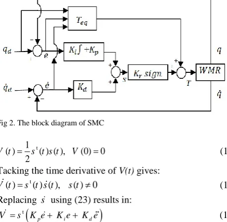
T T K sign s t (16) where, the equivalent control term is obtained using the nominal dynamics model of the WMR which is free of uncertainties. However the second term as a reaching control torque leads to an acceptable tracking performance of the SMC in the presence of probable modeling uncertainties and unknown exogenous inputs which both are considered bounded. Using the SMC according to the block diagram of Fig. 2. the convergence of WMR tracking error e(t) to zero is obtained through holding it on the stable sliding surface. In this way, the tracking error can be moved along the sliding surface to the origin. To guarantee this, the time derivative of the following positive function should be a negative value.
( ( ) ) ( , ) ( )
T M q M q V q q V C C qD
Y
X x
y
(X, Y)
a 2b
Fig 2. The block diagram of SMC
t
1
( ) ( ) ( ), (0) 0 2
V t s t s t V (17) Tacking the time derivative of V(t) gives:
t
( ) ( ) ( ), ( ) 0 V t s t s t s t
(18) Replacing s using (23) results in:
t
p i d
V s K e K eK e (19) Using (15), qis given as:
1 1
1 1
( ) ( ) ( )
( ) [( ) ( ) ]
q M M T M M V V q
M M V V C C q D
(20)
M M is the nonsingular inertial matrix under bounded uncertainties; therefore (20) is simplified as:
1 1 1 1
( ) ( ) ( )
q M M T V V C C qD (21) where, the subscript 1 denotes the new version of corresponding matrices in (14).
Now, t t 1 1 1 1 [ ( )] [ ( ) ( ) ( ) ]
p i d d
p i d d d d d
eq slid d
V s K e K e K q q
s K e K e K q K V K V K M M
T T D K C C q
(22) 1 1 1 1 [ ) ] ( )( ) T
p i d d d d d d
T
d eq slid
s K e K e K q K V K V K Cq K C q
s K M M T T D
(23)
The time derivative of (15) results in: 1
1 1 1
( ) [ ( )
( ) ]
p i d d
s t K e K e K q C C q
V V D M M T
(24) The equivalent control torque is obtained through converging solution of s t( ) for the nominal model in which
1
D and all of (24) are zero.
1 1 1
[ ]
eq d p d i d
T M K K e K K e q Cq V (25) Replacing (25) in (23) leads to
1 1 1 1 1 1 [ ] ( )( ) [ ] ( )( ) T T
p i d d d d d
T
d d d p i
T
d d d d d slid
s s s K e K e K q K V K V K C q
K C q s K M M K M K e K e
K q K Cq K V s K M M T D
(26) 1
1 1 1
1
1
( ) [
] ( ) (
)
T T T T
d d d d p i
T T
d d d d d slid d
s s s K V s K C q s K M K M K e K e K q K Cq K V s K M M T s K M
M D (27) 1 1
1 1 1 1
1
1 1 1
1 { [ ] ( ) ( ) ( )} ( ) T T d d
d d d p i
T
d slid
s s s K C M M C q K V M M V K M M D K q M M K e K e s K M M T
(28) 1
1 1 1
1 1
1 1 1
1
{ ( )
( ) }
( )
T T
d d d
d d p i
T
d slid
s s s K V M M V M M D K q K C M M C q K M M K e K e
s K M M T
(29)
where, the norm operator gives the largest magnitude of the eigenvalues of a matrix.
1
1 1 1
1
1 1 1
1 1 1 [ ( ) ] ( ( ) ( )) ( ) T T d d
d p i
T
d slid
s s s K C M M C q K V
M M D q M M K e K e
M M V s K M M T
(30)
The stability of the SMC (16) requires that s sT 0. Therefore the switching control term is obtained as:
1
1
sign( ) sign( )
( )
sl d
T s s
K M M
(31)
The performance of the SMC (16) strictly depends on the reaching control gain which should be designed with respect to the upper bound of the uncertainties. The high the upper bound of uncertainties the high switching gains should be considered. However, a large switching gain increases the chattering range while a small one cannot satisfy the stability conditions. The desire of reducing the chattering phenomena led to the idea for replacing the sign function with a saturation function which may not remove the chattering phenomena significantly. Therefore, a fuzzy sliding mode control signal is introduced to accelerate the reaching phase and to reduce the chattering while maintaining the sliding behavior.
IV. FUZZY SLIDING MODE CONTROLLER
Mamdani type fuzzy reaching control term is proposed to have the following form:
( ) ( )
r f f
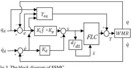
u t K u t (32) where is the normalizing factor. The output fuzzy variable, is continuously adjusted using an if-then rule base with respect to both s and s (s). The configuration of FSMC is shown in Fig. 3.
Using the expertise in design of sliding-mode controllers, a large switching gain will force the state trajectories to approach the sliding surface, s0 rapidly; but at the same time, the chattering is excited. By increasing the tracking errors the value of s will increase; therefore, the switching gain should be correspondingly increased and vice versa. Furthermore, when the state trajectories deviate from the sliding surface, s sT 0, if the value of sis large, the switching gain should be increased to force the trajectories back, and vice versa. When the state trajectories are approaching the sliding surface, s sT 0; therefore if the value of sis large the switching gain should be decreased in order to reduce chattering, and vice versa.
By applying the normalized input variables and , the FSMC law can be developed as:
( ) ( ) ( )
t eq r
Fig 3. The block diagram of FSMC
negative and zero, while S, M, and B denote small, medium, and big, respectively.
Corresponding to the seven membership functions for each input variable, 49 if-then rules of Table I are obtained using the expert engineering knowledge and experiences in the field of WMRs.
V. SIMULATION RESULTS
The effects of the proposed methods to improve the convergence of WMR to reference position and orientation trajectories are evaluated using software simulations. The following sample trajectories are used to produce the reference position and heading angle of the WMR in Cartesian coordinates.
4 3 6 4 8 5
3 10 7 10 5 10
cos (3.9596 ) sin (50 )
sin (3.9596 ) cos (50 )
t t t
aR
X R
b aR
Y R
b
(34)
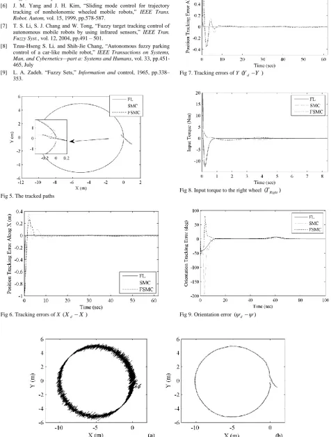
Figs. 5 to 9 show the performance of the designed controllers in the absence of uncertainties and external disturbances. As shown in Fig. 5, using all of the controllers, the WMR has tracked the reference circular trajectory in a significant accuracy. It can be seen from Fig. 6 trough 8 that the FL controller shows a better tracking performance for both position and orientation trajectories compared to those of the sliding mode controllers. However, as shown in Fig. 8, the magnitude of the input torques to the driving wheels is significantly larger when the FL method has been used. Due to the natural conservativeness of the fuzzy systems, the FSMC has resulted in small tracking errors in comparison with that of the SMC. However, the importance of both fuzzy and pure SMCs is understood during affecting the WMR by modeling uncertainties and exogenous unknown but bounded inputs. The simulated performances of the FL and sliding mode controllers to trajectory tracking of the WMR under modeling uncertainties and Gaussian white noises have been shown in Figs. 10 through 14. According to Fig. 10, the FL controller is highly sensitive to measurement noises. However, the SMCs show a relatively high robustness against both uncertainties and measurement noises. From Fig. 11 through 13, a considerable small tracking error along both position and orientation trajectories are resulted using SMC and FSMC methods compared with the FL method. Furthermore, the FSMC has shown a more reliable trajectory tracking performance compared to the SMC. As the other superiority with respect to FL method, the SMC request small input torques of driving wheel. For instance, as it is shown in Fig. 14, the input torque to the right driving wheel of the WMR is considerably large due to using FL controller. However, the requested torques by the SMCs are bounded to a small upper level.
TABLE I. FUZZY LOGIC CONTROLLER RULES
s
s NB NM NS Z PS PM PB
NB PB PB PM PM PS PS Z
NM PB PM PM PS PS Z NS
NS PM PM PS PS Z NS NS
Z PM PS PS Z NS NS NM
PS PS PS Z NS NS NM NM
PM PS Z NS NS NM NM NB
PL Z NS NS NM NM NB NB
Figure 4. Membership function of input/output variables s, sand uf
VI. CONCLUSION
In this paper, the SMCs have been designed to perform perfect trajectory tracking of a general kind of WMRs in which the center of mass is out of the center of rotation. The required input torques by the FL controller which uses a cartesian dynamic model of the WMR results in a superior tracking performance of position and velocity trajectories. However, during affecting the exogenous inputs and modeling uncertainties, the FL controller shows a weak tracking performance associated with high frequency errors. By use of a SMC associated with a PID sliding surface, the tracking performance of the WMR has been improved compared with that obtained using the FL controller. A Mamdani type FSMC has been proposed to further improving the tracking performance of WMR against the uncertainties and measurement noises. Unlike a pure fuzzy logic controller which is encountered to rule expanding problem, the FSMC uses 49 if-then rules in the rule base. Therefore it is more suitable for implementation in real WMR systems.
REFERENCES
[1] Jafar Keighobadi, Mohammad B.Menhaj, and Mansour Kabganan, ―Feedback- linearization and fuzzy controllers for trajectory tracking of wheeled mobile robots,‖ Kybernetes, vol. 39, pp.83-106, March 2010.
[2] Jafar Keighobadi and Mohammad B. Menhaj, ―From nonlinear to fuzzy approaches in trajectory tracking control of wheeled mobile robots,‖ in press.
[4] H. T. Yau, C. L. Kuo and J. J. Yan, ―Fuzzy sliding mode control for a class of chaos synchronization with uncertainties,‖ Int. J. Nonl. Sci. Num. Simul., vol. 7, 2006, pp.333-338.
[5] J. J. E. Slotine and W. Li,―Applied nonlinear control,‖ in Englewood Cliffs, New Jersey: Prentice-Hall, 1991.
[6] J. M. Yang and J. H. Kim, ―Sliding mode control for trajectory tracking of nonholonomic wheeled mobile robots,‖ IEEE Trans. Robot. Autom, vol. 15, 1999, pp.578-587.
[7] T. S. Li, S. J. Chang and W. Tong, ―Fuzzy target tracking control of autonomous mobile robots by using infrared sensors,‖ IEEE Tran. Fuzzy Syst., vol. 12, 2004, pp.491 – 501.
[8] Tzuu-Hseng S. Li, and Shih-Jie Chang, ―Autonomous fuzzy parking control of a car-like mobile robot,‖ IEEE Transactions on Systems, Man, and Cybernetics—part a: Systems and Humans, vol. 33, pp.451-465, July
[9] L. A. Zadeh. ―Fuzzy Sets,‖ Information and control, 1965, pp.338– 353.
[image:5.595.43.286.35.627.2]Fig 5. The tracked paths
[image:5.595.309.520.59.366.2]Fig 6. Tracking errors of X(XdX)
[image:5.595.46.523.96.724.2]Fig 7. Tracking errors of Y(Yd Y )
Fig 8. Input torque to the right wheel (TRight)
Fig 9. Orientation error (d )
Fig 11. Tracking errors of X (XdX); (a) FL; (b) dotted line for SMC and solid line for FSMC
Fig 12. Tracking errors of Y (YdY); (a) FL; (b) dotted line for SMC and solid line for FSMC
Fig 13. Orientation error (d ); (a) FL; (b) dotted line for SMC and solid line for FSMC
[image:6.595.62.519.425.568.2] [image:6.595.63.513.604.758.2]