A New Hydraulic Speed Regulation Scheme: Valve-pump Parallel
Variable Mode Control
Haigang Ding1, Jiyun Zhao1, and Quanmin Zhu2
1School of Mechatronic Engineering, China University of Mining and Technology, Xuzhou 221116, China
2 Department of Engineering Design and Mathematics, University of the West of England, Bristol 161QY, UK
Corresponding author: Haigang Ding (e-mail: haierdhg@ 126.com).
ABSTRACT To improve the comprehensive performances of hydraulic speed regulation systems, this work proposes and develops a new control scheme, valve-pump parallel variable mode control, which can adopt different control modes in different speed regulation stages and can also adjust the weight ratio between pump control and valve control in the control process. In this paper, we design a hydraulic speed regulation in valve-pump parallel variable mode control, explains its principle, establish the system mathematical model, analyze system parameters, build a test system to verify regulation performances. The experimental results show that during the speed adjustment process, the switching between different control modes is smooth, the change rule of proportional valve and variable pump is in accordance with the expectation, and the ratio of valve to pump is reasonable, and the proposed scheme can improve the comprehensive performance of speed governing systems. The valve-pump parallel variable mode control could make full use of advantages of valve control and pump control, and will makes hydraulic control systems more flexible and suitable, and enrich the current control schemes of hydraulic speed regulation systems.
INDEX TERMS hydraulic speed regulation systems; variable mode control; valve control; pump control; valve-pump weight ratio
I. INTRODUCTION
The traditional hydraulic speed control system has two basic forms: valve control and pump control [1-3]. The dynamic response of the valve control system is fast, but the efficiency is low [4,5]; the efficiency of the pump control system is high, but the dynamic response of the system is slow [6,7]. Valve-pump parallel control combines the advantages of the valve control system and the pump control system, and is mainly used to electrohydraulic actuators (EHA) in flights to achieve excellent control performances[8,9]. But at present, the control mode of valve-pump parallel control is too single, and can’t change the control mode according to the speed regulation requirements, so it is hard to apply the applications with obvious speed regulation process, such as hydraulic hoists [10,11]. In view of the above problems, this paper puts forward a valve-pump parallel variable mode hydraulic speed control system, which can adopt different control modes in different speed regulating stages, and can also adjust the weight ratio of pump control and valve control in the process of speed regulation. In this paper, we design the valve-pump parallel variable mode hydraulic speed control system firstly and clarify its working principle. Then, we set up the experimental system and carry out an experimental study of the speed regulation period. The valve-pump parallel variable mode control can enrich the speed regulating mode of the current hydraulic system, making the hydraulic speed regulating system more flexible and adaptable. It also has a wide application value in engineering.
II. SYSTEM DESIGN
In this section, a hydraulic speed regulation system in valve-pump parallel variable mode control is designed (as shown in Figure 1) and its operating principle is explained. In this system, a proportional variable pump (PVP) is parallel with a proportional directional valve (PDV) to regulate the motor speed together. The PDV can work in two states: oil drain and oil replenishing. When the PDV is working at the state of oil replenishing, the valve control source adds the oil to the motor high pressure cavity through the PDV, and the flow that adds into the motor is equal to the sum of the pump control flow and the valve control flow. At this time the system is working at the oil replenishing valve-pump parallel control (RVPC) mode. When the PDV is working at the state of oil drain, the oil liquid from the motor high pressure cavity leaks into the tank through the PDV, and the flow that adds into the motor is equal to the difference between the control flow of the pump and the control flow of the valve. At this time the system is working at the oil leaking valve-pump parallel control (LVPC) mode.
The proposed system is a closed loop control system with multiple input and single output, as shown in Figure 2. In order to show the role of valve control and pump control in the combined speed regulation, we propose a concept of valve-pump weight ratio:𝑘𝑣𝑝= 𝑘𝑣: 𝑘𝑝, where 𝑘𝑣 is the weight of valve control links, and 𝑘𝑝is the weight of pump
control links.
If 𝑘𝑣𝑝>1, it indicates that the function of valve control is
If 𝑘𝑣𝑝<1, it means that the function of pump control is
greater than valve control, so the system is mainly controlled by pump.
1- PVP; 2- valve oil control source; 3- PDV; 4- hydraulic motor; 5- speed encoder; 6-variable mode controller
Fig. 1 The schematic diagram of hydraulic speed regulation systems in valve-pump parallel variable mode control
𝐾𝑝
𝐾𝑣 PDV
PVP Hydraulic motor
Speed feedback
Speed
Ref.
Fig.2 Control principle of valve-pump parallel variable mode control
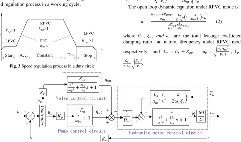
A complex speed regulation process, including start, acceleration, constant speed, deceleration, and stop, is used to hydraulic hoists. Different control performances are required at different stages. The proposed valve-pump parallel variable mode control is applied to the speed regulation process, and the control mode can vary with the control requirements at different stages. Fig. 3 shows the speed regulation process in a working cycle.
Fig. 3 Speed regulation process in a duty circle
(1) At the start-up and stop stages, to improve low speed stability, the system is under the RVPC mode keeping 𝑘𝑣𝑝>1.
(2) At the acceleration and deceleration stages, to save energy, the system is mainly controlled by the variable pump, so 𝑘𝑣𝑝<1, and the system is under parallel pump control
(PPC) mode, and. At this stage, the control valve can stay in the state of oil drain and oil replenishing.
(3)At constant speed stage, to achieve fast repose to load disturbance, the system is under RVPC mode keeping
𝑘𝑣𝑝>1.
III. SYSTEM MATHEMATICAL MODELING AND
PARAMETER ANALYSIS
A. SYSTEM MATHEMATICAL MODELING
The mathematical model of valve-pump parallel control system consists of three links: pump control, valve control and hydraulic motor [12]. We connect these three links and construct the control block diagram [13], as shown in Fig. 4. The open loop dynamic equation under LPVC mode is:
ω =
𝐾𝑝𝑞𝑝0−𝐾𝑣𝑞𝑣0
𝐷m −
𝐶𝑙
𝐷𝑚2(1+
𝑠 2ω𝑙𝜉𝑙)𝑇𝐿 𝑠2
𝜔𝑙2+
2𝜉𝑙
𝜔𝑙𝑠+1
(1)
where ω is the motor angular speed, 𝐷mis the motor
displacement, 𝑞𝑝0 and 𝑞𝑣0 are the pump flow and valve flow without load, respectively, 𝑇𝐿is the load torque, 𝐶𝑙,𝜉𝑙, and 𝜔𝑙 are the total leakage coefficient, damping ratio and natural frequency under LPVC mode, respectively, and 𝐶𝑙=
𝐶𝑡+ 𝐾𝑐𝑙, 𝜔𝑙= √𝛽𝑒𝐷𝑚2 𝑉0 𝐽 ,𝜉𝑙=
𝐶𝑙 2𝐷𝑚√
𝛽𝑒 𝐽 𝑉0.
The open loop dynamic equation under RPVC mode is:
ω =
𝐾𝑝𝑞𝑝0+𝐾𝑣𝑞𝑣0
𝐷m −𝐷𝑚𝐶𝑟2(1+2ω𝑟𝜉𝑟𝑠 )𝑇𝐿 𝑠2
𝜔𝑟2+
2𝜉𝑟
𝜔𝑟𝑠+1
(2)
where 𝐶𝑟, 𝜉𝑟, and 𝜔𝑟 are the total leakage coefficient, damping ratio and natural frequency under RPVC mode,
respectively, and 𝐶𝑟= 𝐶𝑡+ 𝐾𝑐𝑟 , 𝜔𝑟= √𝛽𝑒𝐷𝑚2 𝑉0 𝐽 , 𝜉𝑟= 𝐶𝑟
2𝐷𝑚√ 𝛽𝑒 𝐽
𝑉0.
C
ontr
oll
er
𝐾𝑞𝑥 𝑠2 𝜔𝑣2+
2𝜉𝑣 𝜔𝑣𝑠 + 1
𝑞𝑣0
𝑢𝑣
𝐾𝑢 𝑠 𝜔𝑏𝑝 + 1
𝑞𝑝0
𝐾𝑚
1 𝐷𝑚
𝐶𝑥
𝐷𝑚2
(1 + 𝑠 2ω𝑥𝜉𝑥
)
1
𝑠2 𝜔𝑥2+
2𝜉𝑥 𝜔𝑥𝑠 + 1
𝑢𝑝
𝑢𝑚 𝜔
𝐾𝑝 𝐾𝑣
60 2𝜋
Valve control circuit
Pump control circuit Hydraulic motor control circuit
𝑛𝑚 𝑇𝐿
LPVC PPC
M
o
to
r
sp
ee
d
Start Acc. Constant Stop
LPVC RPVC
Dec.
𝑘𝑣𝑝>1
𝑘𝑣𝑝>1 𝑘𝑣𝑝>1
[image:2.576.72.252.107.193.2] [image:2.576.49.267.248.314.2] [image:2.576.54.532.422.705.2]B. PARAMETER ANALYSIS
Comparing with the traditional pump control system, the parameters of the valve-pump parallel system have the characteristics as follow:
(1) The natural frequency of the system remains constant. According to the expression of the natural frequency of the system, the natural frequency is equal between the valve-pump parallel system and the single pump control system. We can find that the hydraulic natural frequency of the pump control system does not change after adding the valve control.
(2) The total leakage coefficient is increased and the change is significant. The total leakage coefficient of the traditional pump control system is 𝐶𝑡, and its value is small and stable [14]. When the valve control introduced, the total leakage coefficient of the valve-pump parallel system should plus the valve flow-pressure coefficient 𝐾𝑐𝑟 or 𝐾𝑐𝑙, and
𝐾𝑐𝑙= 𝐶𝑠𝑣𝑢𝑣
2√𝑃ℎ , 𝐾𝑐𝑟= 𝐶𝑠𝑣𝑢𝑣
2√𝑃𝑠−𝑃ℎ. 𝐾𝑐𝑟 and 𝐾𝑐𝑙 are both much
larger than 𝐶𝑡, and they have biggish change with the working point (valve input signal 𝑢𝑣 and system pressure 𝑃ℎ) [15], so compared with the single pump control system, the total leakage coefficient of the valve-pump parallel system is larger and more significant.
(3) The damping ratio increases and changes significantly with the working point. As the damping ratio is proportional to the total leakage coefficient of the system, the damping ratio of the valve-pump parallel system increases and changes with the working point significantly compared with the single pump control system.
(4) The speed stiffness dents. As the velocity stiffness is inversely proportional to the total leakage coefficient, and the total leakage coefficient of the valve-pump parallel system is much greater than that of the pump control system. So the speed stiffness of the valve-pump parallel system is less than the pump control system.
(5) The speed of response increases. As long as the 𝐾𝑝
and 𝐾𝑣 are set up reasonably, the opening gain of the
valve-pump parallel control system is greater than that of the separate valve control or pump control system, so that the response speed of the valve-pump parallel control system is greater than that of the separate valve control or pump control system.
IV. EXPERIMENT AND ANALYSIS
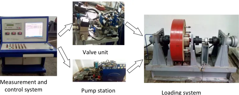
We build valve-pump parallel variable mode control experimental system, as shown in Fig. 5. The main parameters of the test system are as follows: rated pressure 20MPa, rated flow rate 50L/min (including pump control flow 40L/min and valve control flow 10L/min), maximum motor speed 90r/min, and rotational inertia 48kg∙m2. The system uses the hydraulic
motor to load, and the loading pressure regulates by a proportional relief valve.
PI compensation is used to correct the pump control circuit and pump circuit, and the PI parameters are shown in Table 1.
From Equations (1) and (2), we know valve-pump parallel variable model control system is unstable before compensation, so PI compensation is used to correct the
pump control circuit and pump circuit, and the its
transfer function is given by
𝐺𝑐= 𝐾𝑐(1 + 1
𝑇𝑖𝑠) = 𝐾𝑐+ 𝐾𝐼
𝑠 (3)
where 𝐾𝑐is the proportional gain, 𝑇𝑖is the internal time, 𝐾𝐼
is the internal gain and 𝐾𝐼= 𝐾𝑐/𝑇𝑖. The PI parameters for
different control circuits are shown in Table 1. A variable mode controller is developed, and control modes could be switched between LVPC, RPVC and PPC according to control requirements, and the setting of valve pump weight in each speed regulation stage [16] is shown in
Table 2.
Fig.5 Experimental System
Measurement and control system
Valve unit
[image:3.576.98.483.524.678.2]Table 1 PI parameter setting of different control circuits
Control circuit 𝐾𝑐 𝑇𝑖 𝐾𝐼
speed rang [r/min]
Pump control 0.3 0.18 1.67 All
Leaking Valve control
for
0.6 0.12 5 0~15
Replenishing
[image:4.576.42.275.212.651.2]Valve control 0.7 0.12 5.8 55~70
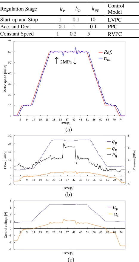
Table 2 Proportion Setting of valve and pump in different speed regulation stage
Regulation Stage 𝑘𝑣 𝑘𝑝 𝑘𝑣𝑝 Control Model
Start-up and Stop 1 0.1 10 LVPC
Acc. and Dec. 0.1 1 0.1 PPC
Constant Speed 1 0.2 5 RVPC
(a)
(b)
(c)
Fig. 6 Dynamic response in a speed regulation cycle. (a) speed response of driving motor;(b) pressure and flow; (c) controlling
voltage of pump and valve
Fig. 6 is the system dynamic response in a speed
uniform speed section. Here we can obtain the following results from the experiments.
(1)Compared with the pump control, the LVPC in the low speed section can improve the motor speed stability. The RVPV in the constant speed section can realize the rapid adjustment of the step load interference.
(2) During the whole speed regulation process, the speed tracking characteristics is good and the steady-state accuracy is well.
(3) The control mode switches smoothly, the signal of the change trend of control comes to expected and smooth conversion. It achieves the smooth changing between the valve control of oil drain and oil replenishing.
(4) During the whole speed adjustment process, the variable pump provides most of the flow while the proportional directional valve is in a small flow state, so the system efficiency is relatively high.
V. CONCLUSION
In this paper, to achieve excellent comprehensive performances for complex speed regulation systems, a new hydraulic control scheme called valve-pump parallel variable mode control is developed, which could vary control model with the control requirements, and different control modes are applied to different regulation stages. The LVPC mode is applied to the start-up and stop stages to improve the low speed stability; the RVPC is used to the constant speed stage to achieve the fast regulation to load disturbance; the PPC mode is applied to the acceleration and deceleration stages to save system energy.
Valve-pump parallel variable mode control, using double channels of valve control and pump control, is established by changing the weight ratio of valve and pump control which is based on control requirements and flexible control mechanism, to realize the comprehensive performance of high power hydraulic speed control system, such as low speed starting and stopping smooth, fast adjustment, high efficiency.
By combining the valve control, the leakage coefficient, damping ratio and other parameters of the valve-pump parallel variable mode hydraulic system changes with the change of the valve opening and the system pressure, which will increase the parameter prediction and control difficulty of the system. This paper only uses the traditional PID control. In the future, we will study the advanced control strategy to adapt to the changes of system parameters, so that we can improve the comprehensive performance of the system further more.
ACKNOWLEDGEMENTS
This work is supported by a Project Funded by the Priority Academic Program Development of Jiangsu Higher Education Institutions, and the Natural Science Foundation of Jiangsu Province of China (BK20150186). The authors
0 10 20 30 40 50 60 70
5 9 14 19 23 28 33 37 42 46 51 56 60 65 70 74
M
ot
or
sp
ee
d
[r/
m
in
]
Time [s]
设定转速 实际转速
0 2 4 6 8
-6 0 6 12 18 24 30
5 9 14 19 23 28 33 37 42 46 51 56 60 65 70 74
Fl
ow
[L
/m
in
]
Time [s]
泵流量 阀流量 高压侧压力
P
re
ss
ur
e
[M
P
a]
-6 -4 -2 0 2 4 6 8
5 9 14 19 23 28 33 37 42 46 51 56 60 65 70 74
C
on
tro
l v
ol
ta
ge
[V]
Time [s]
泵电压 阀电压
2MPa
─ Ref.
─ 𝑛𝑚
─𝑞𝑝 ─ 𝑞𝑣
─𝑃ℎ
would like to thank the editors and anonymous reviewers for their constructive advices.
CONFLICT OF INTEREST
The authors declare that there is no conflict of interest regarding the publication of this paper.
REFERENCES
[1] N. D. Manring, “Hydraulic Control Systems”, New York, John
Wiley & Sons, 2005.
[2] N. D. Manring, “Mapping the efficiency for a hydrostatic
transmission”, ASME J. Dynamic Systems, Measurement and
Control, 2007, 138(3), pp. DS-15-1105.
[3] T.L. Lin, L. Wang, Huang W. P., et al,, “Performance analysis of an automatic idle speed control system with a hydraulic accumulator for pure electric construction machinery”, Automation in Construction, 2017, 84, pp. 184-194,
[4] G. Shen, Z. C.Zhu, J. S. Zhao, et al., “Real-time tracking control of electro-hydraulic force servo systems using offline feedback
control and adaptive control”, ISA Transactions, 2017, 67(3),
pp. 356-370.
[5] M. Paloniitty and M. Linjama, “High-linear digital hydraulic valve control by an equal coded valve system and novel
switching schemes”, Proceedings of the Institution of
Mechanical Engineers, Part I, Journal of Systems and Control Engineering, 2018, 232(3), pp. 258 -269.
[6] J.Yao, P. Wang, X. M.Cao, et al., “Independent volume-in and volume-out control of an open circuit pump-controlled
asymmetric cylinder system”, Journal of Zhejiang University
SCIENCE A, 2018, 19(3), pp. 203-210.
[7] Z.Y. Quan, L. Quan, J.M. Zhang, “Review of energy efficient direct pump controlled cylinder electro-hydraulic technology”, Renewable and Sustainable Energy Reviews, 2014, 35(7), pp. 336-346.
[8] Z. L. Wang, “Modern electric hydraulic servo control”, Beihang University press, Beijing, 2004, pp. 120-130.
[9] R.J. Kang, Z.X. Jiao, S.P. Wang, “Design and Simulation of Electro-hydrostatic Actuator with a Built-in Power Regulator”, Chinese Journal of Aeronautic, 2009, 22(6), pp.700-706. [10] H. G. Ding, J. Y. Zhao, and L. Zhao, “Analysis on
electrohydraulic speed servo control schemes for anti-explosion
hydraulic hoisters”, Journal of the China Coal Society, 2011,
36(8), pp. 1407-1411.
[11] H. G. Ding and J. Y. Zhao, “Characteristic analysis of pump controlled motor speed servo in the hydraulic hoister”, International Journal of Modelling, Identification and Control, 2013, 19(1), pp. 64-74.
[12] H. G. Ding and J. Y. Zhao, “Dynamic characteristic analysis of replenishing/ leaking parallel valve control systems”, Automatika, 2017, 58(2), pp.182-194.
[13] H. G. Ding and J. Y. Zhao, C. Cao, “Valve–pump parallel variable mode control for hydraulic speed regulation of
high-power systems”, Advances in Mechanical Engineering, 2017,
9(10), pp. 1-16.
[14] B. Xu, R. Q. Ding, J. H. Zhang, et al., “Pump/valves coordinate control of the independent metering system for mobile
machinery”, Automation in Construction, 2015, 57, pp. 98-111.
[15] L. H Manring. and N. D. Manring, “Mapping the efficiency of a double acting, single-rod hydraulic-actuator using a critically centered four-way spool valve and a load-sensing
pump”, ASME J. Dynamic Systems, Measurement and
Control, 2018, 140(9), pp. DS-17-1367.
[16] H. G. Ding, J. Y. Zhao, G. Cheng, et al., “The influence of valve-pump weight ratios on the dynamic response of leaking valve-pump parallel control hydraulic systems”, Appl. Sci. 2018, 8 (7), pp.1201-1215.
Haigang Ding was born in Huaibei, Anhui, China in 1981. He received the B.S. in mechanical engineering from the Chang’ an University, China in 2004, M.S. degrees in mechanical design and theory from China University of Mining and Technology (CUMT), China in 2009, and the Ph.D. degree in mechatronic engineering from CUMT, China in 2014.
Since 2014, he has been a lecture with the School of Mechatronic Engineering, CUMT. Currently, he is acting as a master supervisor and header of Electro- hydraulic Control Lab of CUMT. He is the author of more than 20 articles cited by SCI/EI, and more than 5 inventions. His research interests include fluid transmission and control, electro-hydraulic control of construction machinery, and novel hydraulic components. Dr. Ding is also an invited reviewer of SCI international journals, such as IMechEng-Part C/ Part I, IEEE Access, IJMIC, AIME, etc.
Jiyun Zhao was born in Lianyungang, Jiang Su, China in 1966. He received the B.S. and M.S. degrees in mechanical engineering from CUMT, China in 1988 and 1992 and the Ph.D. degree in mechatronic engineering from Shanghai Jiao Tong University, China in 1999.
From 2003 to 2004, he was a public visiting scholar
with Mechanical and Electronic Engineering
Laboratory of the University of Toronto, Canada. Since 2004, he has been a Professor with the School of Mechatronic Engineering, CUMT, and acts as a doctor supervisor. He is the author of two books, more than 100 articles, and more than 20 inventions. His research interests include fluid transmission and control, water-based components and systems, mining machinery design and theory.
Quanmin Zhu was born in Xuzhou, Jiang Su,
China in 1955. He obtained the MSc degree at Harbin Institute of Technology, China in 1983 and the Ph.D. degree at the Faculty of Engineering, University of Warwick, UK in 1989. Since 1996, he has been a professor with the Department of Engineering Design and Mathematics, University of the West of England, Bristol, UK.