Multi-Level Inverter with Facts Capability for Reliable
Power Distributions Using Wind Energy as Source
K.Durga Prasad1,G.Venkateswarao2
M.Tech(research scholar)1,Assistant professor2in Dept. of electrical and electronics engineering kakinada institute of engineering & technology- 2
Email:[email protected];[email protected]
Abstract-The paper manages the multilevel converters control procedure for photovoltaic framework coordinated in dispersion matrices. The proposed control plan guarantees the infusion of the produced power in the conveyance network with quick element reaction, while giving an extra dynamic force sifting ability giving the required consonant and responsive streams to be considered. The control plan is accepted by method for reenactments with a course converter which interfaces to a dispersion network. Additionally, for DC join voltage control, it is required that balances out the voltage at the inverter data to protect a ceaseless stream of vitality trade between the matrix and the PV framework. Likewise, a LC channel is important to channel the yield current and voltage from the sounds and to shield the network from their ruinous impact. At long last, this paper presents nitty gritty demonstrating of the framework joined photovoltaic era framework parts, in Simulink/Mat lab programming. Recreation results displayed to approve the parts models and the picked control plans. The outline and correlation of multi-level inverter with D-STATCOM for wind vitality frameworks utilizing Modular Multi-level Converter (MMC). The point of the work is to outline diverse levels of inverter with FACTS gadgets to give utilities more learning about the appropriation frameworks, particularly toward the end focuses. Henceforth made the correlation between these levels of inverters where the yield of the framework does not change with the levels of inverter but rather the Total Harmonic Distortion (THD) of the framework will lessens as the level increments. This inverter is put between the wind turbine and the conveyance network where the dynamic and responsive force is direct which is required by the lattice. Recreations of the proposed inverter with 11 level and 17 level have been done in MATLAB/Simulink. The reenactment results accept the execution of the proposed control system.
Keywords—level Inverter, Modular Multi-level Converter (MMC), STATCOM
I. Introduction
Renewable energy sources (RESs) have encountered a quick development in the most recent decade because of mechanical enhancements, which have logically diminished their expenses and expanded their proficiency in the meantime [1]. In addition, the need to depend less on fossil energizes and to decrease outflows of nursery gasses, requires an increment of the power created by RESs. This can be proficient mostly by turning to wind and photovoltaic era, which, in any case, presents a few issues in electric frameworks administration because of the innate way of these sorts of RESs [2]. Truth be told, they are both portrayed by ineffectively unsurprising vitality generation profiles, together with exceedingly variable rates. As an outcome, the electric framework can't deal with these irregular force sources past specific points of confinement, bringing about RES
era diminishing’s and, thus, in RES infiltration levels
circumstances over customary vitality sources, for example, common gas or coal. They are perfect wellsprings of vitality that can be found in many districts without radiating any nursery gasses. Renewable vitality is rich and free, and by and large not influenced by political unsteadiness. The fundamental inconvenience of renewable vitality sources is that they are for the most part situated in remote ranges and far from substantial burdens. Also, the utilization of renewable vitality sources is restricted by the way that they are not generally accessible. Power electronic-based adaptable AC transmission System (FACTS) gadgets have been produced with a specific end goal to give more information and control on force frameworks. Customarily, capacitor banks have been utilized to control the responsive force on a force framework, yet with arrangement of force hardware in force frameworks, STATCOMs were conceived and got more consideration amid late years. The point of this work is to join the two ideas of inverters and D-STATCOMs into a supposed D-STATCOM inverter keeping in mind the end goal to appreciate the advantages of an inverter with DSTATCOM capacity with no extra cost. A multilevel D-STATCOM inverter is a force electronic gadget that is put between a renewable vitality source and a dissemination framework to give dynamic force, as well as to control receptive force on the framework. Multi-level converters have a few preferences contrasted with the customary two level converters. They have the ability to perform at a lower exchanging recurrence, they have lower aggregate consonant twisting (THD), and they have less dv/dt crosswise over switches and thusly less voltage weight on the gadgets [2-6]. The proposed D-STATCOM inverter in this paper could substitute existing inverters utilized for renewable vitality frameworks, particularly for little to medium sized wind applications.
II. Multilevel Inverteropologies And Control Techniques
Diode Clamped Inverter
Effective control technique for medium voltage high-power induction motor fed by cascaded neutral-point-clamped inverter [3]. [4], five/nine level twelve-switch inverter for three-phase high speed electric machines having a low per-unit leakage reactance is described. [5], used a new single-inductor multi-output dc/dc converter that can control the dc-link voltages of a single-phase diode clamped inverter asymmetrically to achieve voltage quality enhancement. [6], comparative analysis between the classical structure of Neutral Point Clamped (NPC) and the emerging Active NPC converters. [7], DC
bus short circuit protection is usually done using the sensed voltage across collector and emitter (i.e., VCE sensing), of all the devices in a leg. [8], introduced a new nine-level active neutral point- clamped (9L ANPC) converter for the grid connection of large wind turbines (WTs) to improve the waveform quality of the converter output voltage and current. [9], investigations of dc-link voltages balance with the use of a passive RLC circuit in a single-phase diode clamped inverter composed of two three-level legs. [10], three-level active neutral point- clamped zero-current-transition (3L-ANPC ZCT) converter for the sustainable energy power conversion systems. [11], new modulation techniques for three-phase transformer less neutral point clamped inverters to eliminate leakage currents in photovoltaic systems without requiring any modification on the multilevel inverter.[12], comparison between three level diode neutral-pointclamped zero-current transition (DNPC-3L ZCT) inverter and three-level active neutral-point clamped zero-current-transition (ANPC-3L ZCT) inverter, with respect to switching energy, volume, as well as parasitic inductance influence, the topologies are compared.
Cascaded Multilevel Inverter
of singlephase sub multilevel converter units and full-bridge converters then, the structure is optimized. Flying Capacitor Multilevel Inverter
Mathematical analyses of the balancing process in boost and buck–boost converters and investigations of voltage sharing stabilization with the use of passive RLC circuit in switch-mode flying capacitor dc–dc converters are presented. [23], topology of flying capacitor multilevel converter which has several terminals of different dc voltage and an ac voltage terminal proposed to utilize the topology as an integrated power conversion module.[24], control strategy of flying capacitors multilevel inverters. The analysis of the permissible switching states, especially the possibility of the multiple commutations is carried out. [25], the stabilization of the input DC voltages of five level flying capacitors (FLFC) voltage source inverters (VSI). A feedback control algorithm of the rectifier is proposed. [26], an experimental photovoltaic (PV) power conditioning system with line connection in which the conditioner consists of a flying capacitors multi-cell inverter fed by a dc-dc boost converter is carried out. [27], two active capacitor voltage balancing schemes are proposed for single-phase (Hbridge) flying-capacitor multilevel converters, based on equations of flying capacitor converters. The methods are effective on capacitor voltage regulation in flying-capacitor multilevel converters.
Sinusoidal Pwm
multicarrier sub-harmonic pulse width modulation (PWM), called disposition band carrier and phase-shifted carrier PWM (DBC-PSC-PWM), method is developed to produce output voltage levels of (n ×m + 1) and to improve the output voltage harmonic spectrum with a wide output frequency range. [29], carrier-based closed-loop control technique has been developed to reduce the switching losses based on insertion of ‗no switching‘ zone within each half
cycle of fundamental wave. [30], five-level pulse width modulation inverter configuration, including chopper circuits as DC current-power source circuits using small smoothing inductors, is verified through computer simulations and experimental tests. [31], designed a seven-level flying capacitor multilevel inverter by using sinusoidal pulse width modulation technique. [32], addressed a modified Sinusoidal Pulse Width Modulation (SPWM) modulator with phase disposition that increases output waveform up to 7- level while reducing output harmonics.[33], pulsewidth modulation (PWM) for single-phase five-level inverter via field-programmable gate array (FPGA) is carried out.
Space Vector Pwm
Two discontinuous multilevel space vector modulation (SVM) techniques are implemented for DVR control to reduce inverter switching losses maintaining virtually the same harmonic performance as the conventional multilevel SVM for high number of levels. [35], two carrierbased modulation techniques for a dual two-level inverter with power sharing capability and proper multilevel voltage waveforms were introduced. Their main advantage is a simpler implementation compared to SVM. [36], focused a novel 3-D space modulation technique with voltage balancing capability for a cascaded seven-level rectifier stage of SST.
IV. About Wind System
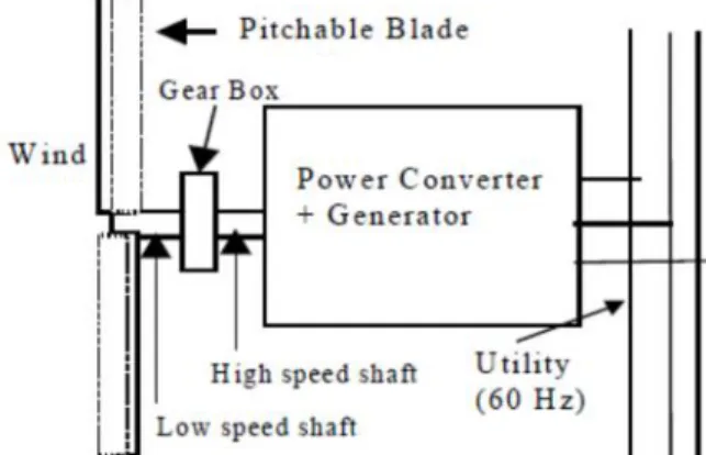
Wind is a form of solar energy. Winds are caused by the uneven heating of the atmosphere by the sun, the irregularities of the earth's surface, and rotation of the earth. Wind flow patterns are modified by the earth's terrain, bodies of water, and vegetative cover. This wind flow, or motion energy, when "harvested" by modern wind turbines, can be used to generate electricity. The terms "wind energy" or "wind power" describe the process by which the wind is used to generate mechanical power or electricity. Wind turbines convert the kinetic energy in the wind into mechanical power. This mechanical power can be used for specific tasks (such as grinding grain or pumping water) or a generator can convert this mechanical power into electricity to power homes, businesses, schools, and the like.
Fig. wind energy system
photovoltaic, and wind turbines. Globally, the long-term technical potential of wind energy is believed to be five times total current global energy production, or 40 energy system time’s current electricity
demand. This could require wind turbines to be installed over large areas, particularly in areas of higher wind resources. Offshore resources experience average wind speeds of ~90% greater than that of land, so offshore resources could contribute substantially more energy.
V. Boost Circuit And Its Control
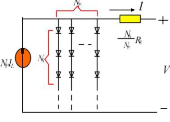
Since the output voltage of PV cell is low, the use of boost circuit will enable low-voltage PV array to be used, as a result, the total cost will be reduced. A capacitor is generally connected between PV array and the boost circuit, to reduce high frequency harmonics. Figure 5 shows the configuration of the boost circuit and its control system. The modeling of this converter depends on the analysis of the various sequences of operation whereas it has been supposed that durations fixed by a control element U. There are two sequences of operation depending on the state of the switch S, each one can be represented by a differential equation as explained in references.
Figure. Boost circuit and its control VI. Details Of Inverter With D-Statom Configuration of the MMC Topology
At this time, the modular multilevel converter (MMC) is the newest topology for large scale commercial applications. Fig. 2 shows the configuration of the MMC topology. The structure of this topology is based on several modules in which each module consists of a floating capacitor and two switches. This topology is an ideal choice for FACTS applications if the capacitor voltages are kept balanced. It requires only one DC source which is proper for renewable energy inverters, it is easy to design for higher levels, and it can deliver active and reactive power regardless of the load characteristics. MMC has a modular design based on identical converter cells [9],[10],[11] which make it a suitable choice for high-level applications. The main drawback of this topology is that it requires large capacitors in comparison with similar topologies
which may affect the total cost of the inverter. However, this problem can be alleviated by the lack of need for any snubber circuits. Each leg of an n-level MMC inverter consists of several basic sub modules (SMs) and two inductors which are in series.
Fig. Complete configuration of the proposed D-STATCOM inverter system
VII. Proposed System
The proposed inverter is equipped with a D-STATCOM option to regulate the reactive power of the local distribution lines and can be placed between the wind turbine and the grid, same as a regular WEI without any additional cost. The function of the proposed inverter is not only to convert dc power coming from dc link to a suitable ac power for the main grid, but also to fix the PF of the local grid at a target PF by injecting enough reactive power to the grid. In the proposed control strategy, the concepts of the inverter and the D-STATCOM have been combined to make a new inverter, which possesses FACTS capability with no additional cost. The proposed control strategy allows the inverter to act as an inverter with D-STATCOM option when there is enough wind to produce active power, and to act as a D-STATCOM when there is no wind. The active
power is controlled by adjusting the power angle δ,
which is the angle between the voltages of the inverter and the grid, and reactive power is regulated by the modulation index m.
There are a large number of publications on integration of renewable energy systems into power systems. A list of complete publications on FACTS applications for grid integration of wind and solar energy was presented in some publications. In some published papers, new commercial wind energy converters with FACTS capabilities are introduced without any detailed information regarding the efficiency or the topology used for the converters. In one published paper, a complete list of the most important multilevel inverters was reviewed. Also, different modulation methods such as sinusoidal pulse width modulation (PWM), selective harmonic elimination, optimized harmonic stepped waveform technique, and space vector modulation were discussed and com-pared. Among all multilevel topologies, the cascaded H-bridge multilevel converter is very well known for STATCOM applications for several reasons. The main reason is that it is simple to obtain a high number of levels, which can help to connect STATCOM directly to medium voltage grids. The modular multilevel converter (MMC) was introduced in the early 2000s. With reference to some published papers describes a MMC converter for high voltage DC (HVDC) applications. This project mostly looks at the main circuit components. Also, it compares two different types of MMC, including H-bridge and full-bridge sub modules. In a publication new single-phase inverter using hybrid-clamped topology for renewable energy systems is presented.
The proposed inverter is placed between the renewable energy source and the main grid. The main drawback of the proposed inverter is that the output current has significant fluctuations that are not compatible with IEEE standards. The authors believe that the problem is related to the snubber circuit design. Several other applications of custom power electronics in renewable energy systems exist, including an application of a custom power interface where two modes of operation, including an active power filter and a renewable energy STATCOM. Another application looks at the current-source inverter, which controls reactive power and regulates voltage at the point of common coupling (PCC). Varma et al, an author propose an application of photovoltaic (PV) solar inverter as STATCOM in order to regulate voltage on three-phase power systems, for improving transient stability and power transfer limit in transmission systems. The authors called their proposed system PV-STATCOM. Similar to wind farms (when there is no wind), solar farms are idle during nights. We proposed a control strategy that makes the solar farms to act as STATCOMs during night when they are not able to produce active
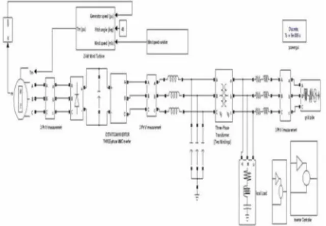
power. The main purpose of the PV-STATCOM system is to improve the voltage control and the PF correction on three-phase transmission systems. In this project, the proposed WEI utilizes MMC topology, which has been introduced recently for HVDC applications. Replacing conventional inverters with this inverter will eliminate the need to use a separate capacitor bank or a STATCOM device to fix the PF of the local distribution grids. Obviously, depending on the size of the power system, multiple inverters might be used in order to reach the desired PF. The unique work in this project is the use of MMC topology for a single-phase voltage-source inverter is able to control the PF of the grid regardless of the wind speed Fig.1.1 shows the complete grid-connected mode configuration of the proposed inverter. The dc link of the inverter is connected to the wind turbine through a rectifier using MPPT and its output terminal is connected to the utility grid through a series-connected second-order filter and a distribution transformer.
VII. Simulation Results
This is divided into two parts. First shows the design of an 11-level MMC inverter was carried out in MATLAB/Simulink. The simulation is 20 s long and contains severe ramping and de-ramping of the wind turbine. The goal is to assess the behavior of the control system in the worst conditions. Second part shows the design of 17 level inverter showing the improved power factor and less THD.
Eleven Level inverter
The following figures describe the 11 level inverter and its sub components. Fig 6.1 shows the simulation circuit diagram for 11 level inverter. As inverter used is a 3 phase system each phase has a multi module converter. Depending on the level of the inverter number of sub modules is presented. Fig 6.2 shows 3 phase multi module converter. Fig 6.3 shows multi module converter. Fig 6.4 shows circuit diagram for sub module.
Fig 6.2 Three phase multi module converter
Fig. 6.6. Simulated output active power from the wind turbine.
Fig 6.6 shows the output active power from the wind turbine. In the simulation, the local load makes the PF 0.82. When the simulation starts, the inverter provides enough compensation to reach the target PF 0.90.
Fig. 6.8 Active and reactive power of the power lines
Fig. 6.7 and Fig 6.8 show the output active and reactive power from the wind turbine and the power lines. After t = 6 s, the output power of the wind turbine is increased, and as a result the level of active
power provided by the feeder line is decreased by the same amount.
Fig. 6.9 Simulated output voltage of an 11-level inverter.
The simulated output voltage of the inverter before the filter is shown in Fig. 6.9 and Fig. 6.10 shows the PF of the grid.
Fig 6.13 Grid voltage and Current
Fig 6.14 THD analysis report
Fig 6.14 shows THD analysis report. By this can say that THD of the system 10.87%.
. Fig 6.16 3 Phase multi module converter
Fig 6.20 Output voltage of 17 level inverter In the figure the output voltage is from -1700 to 1700 voltage level clearly saying that it is alternating. By keeping the filters at the output of the inverter we convert into the smoother waveform.
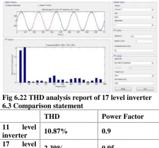
Fig 6.22 THD analysis report of 17 level inverter 6.3 Comparison statement
THD Power Factor
11 level
inverter 10.87% 0.9
17 level
inverter 2.39% 0.95
Table 6.2 Comparison statement
By seeing above table 6.2 we can say THD was reduced and power factor is increased. In seventeen
level inverter, what happens was that the inverter transfers the whole active power of the wind, excluding its losses, to the grid. The amount of reactive power is dictated by the target PF. When the active power from the wind turbine increases, the controller increases the power angle δ in order to output more active power to the grid in order to decrease the dc link voltage.
IX. Conclusion And Future Scope Conclusion
In this project, the concept of a new multilevel inverter with FACTS capability for small-to-mid-size wind installations is presented. The proposed system demonstrates the application of a new inverter with FACTS capability in a single unit without any additional cost. Replacing the traditional renewable energy inverters with the proposed inverter will eliminate the need of any external STATCOM devices to regulate the PF of the grid. Clearly, depending on the size of the compensation, multiple inverters may be needed to reach the desired PF. This shows a new way in which distributed renewable sources can be used to provide control and support in distribution systems. The proposed controller system adjusts the active power by changing the power angle (delta) and the reactive power is controllable by the modulation index m. The simulation results for an 11-level inverter and 17 level inverter with D-STATCOM capability are simulated in MATLAB Simulink. Active power, reactive power, power factor and THD of 11 level inverter with facts capability are presented which within specified ranges. Power factor and THD of 17 level inverter with D-STATCOM capability are improved as compared with corresponding parameters of 11 level inverter with facts capability.
Future scope
In 17 level inverter needs 8 bridges , each H-bridge 4 switches. The total switches used in designing 17 level inverter was 32 switches in which circuits become complicated, cost and size increases. So I decided to create a reduced switch count i.e., creating 17 level inverter with 17 switches in which circuit less complicated ,reduced cost and size References
[1] Kuo-Ching Tseng and Chi-Chih Hung “High
step-up High-Efficiency Interleaved Converter With Voltage Multiplier Module for Renewable energy system”, IEEE Trans. Ind.Electron., vol. 61, no. 3, pp. 0278–0046, March. 2014.
[2] Y. P. Hsieh, J. F. Chen, T. J. Liang, and L. S.
Yang, “Novel high step-up DC–DC converter for
[3] Y. Zhao, X. Xiang, W. Li, X. He, and C. Xia,
“Advanced symmetrical voltage quadrupler rectifiers
for high step-up and high output-voltage converters,”
IEEE Trans. Power Electron., vol. 28, no. 4, pp. 1622–1631, Apr. 2013
[4] A. Beekmann, J. Marques, E. Quitmann, and S.
Wachtel, “Wind energy converters with FACTS
capabilities for optimized integration of wind power
into transmission and distribution systems,” inProc.
CIGRE/IEEE PES Joint Symp. Integr. Wide, Scale Renew. Resour. Power Del. Syst. , Jul. 2009, pp. 1–9. [5] J. Rodriguez, J. S. Lai, and F. Z. Peng,
“Multilevel inverters: Survey of topologies, controls, and applications,” IEEE Trans. Ind. Appl. , vol. 49,
no. 4, pp. 724–738, Aug. 2002.
[6] F. Z. Peng, J. S. Lai, J. W. McKeever, and J.
VanCoevering, “A mul-tilevel voltage-source inverter with separate DC sources for static Var
generation,” IEEE Trans. Ind. Appl. , vol. 32, no. 5,
pp. 1130–1138, Oct. 1996.
[7] L. M. Tolbert and F. Z. Peng, “Multilevel
converters as a utility interface for renewable energy
systems,” in Proc. IEEE Power Eng. Soc. Summer
Meeting, vol. 2. Jul. 2000, pp. 1271–1274.
[8] S. Kouro, M. Malinowski, K. Gopakumar, J. Pou,
L. G. Franquelo, B. Wu, et al., “Recent advances and
industrial applications of multilevel converters,”
IEEE Trans. Ind. Electron. , vol. 57, no. 8, pp. 2553–
2580, Aug. 2010.
[9] C. Tareila, P. Sotoodeh, and R. D. Miller,
“Design and control of a single-phase D-STATCOM
inverter for wind application,” in Proc. PEMWA, Jul.
2012, pp. 1–5.
[10] B. Gultekin and M. Ermis, “Cascaded multilevel
converter-based trans-mission STATCOM: System design methodology and development of a 12 kV ±
12 MVAr power stage,” IEEE Trans. Power Electron.