R E S E A R C H
Open Access
A cross-layer optimization framework for
congestion and power control in cognitive
radio ad hoc networks under predictable
contact
Long Zhang
1*, Fan Zhuo
1and Haitao Xu
2Abstract
In this paper, we investigate the cross-layer optimization problem of congestion and power control in cognitive radio ad hoc networks (CRANETs) under predictable contact constraint. To measure the uncertainty of contact between any pair of secondary users (SUs), we construct the predictable contact model by attaining the probability distribution of contact. In particular, we propose a distributed cross-layer optimization framework achieving the joint design of hop-by-hop congestion control (HHCC) in the transport layer and per-link power control (PLPC) in the physical layer for upstream SUs. The PLPC and the HHCC problems are further formulated as two noncooperative differential game models by taking into account the utility function maximization problem and the linear differential equation constraint with regard to the aggregate power interference to primary users (PUs) and the congestion bid for a bottleneck SU. In addition, we obtain the optimal transmit power and the optimal data rate of upstream SUs by taking advantage of dynamic programming and maximum principle, respectively. The proposed framework can balance transmit power and data rate among upstream SUs while protecting active PUs from excessive interference. Finally, simulation results are presented to demonstrate the effectiveness of the proposed framework for congestion and power control by jointly optimizing the PLPC-HHCC problem simultaneously.
Keywords:Cognitive radio, Cross-layer optimization, Congestion control, Power control, Predictable contact
1 Introduction
1.1 Background and motivation
Cognitive radio (CR) [1] has been widely recognized as a
critical technique to mitigate the spectrum scarcity problem and enhance the overall efficiency of spectrum usage, aim-ing to accommodate for the evolution of wireless systems
towards 5G [2]. In a CR network (CRN), unlicensed
sec-ondary users (SUs) are allowed to opportunistically access the spectrum allocated to licensed or primary users (PUs) without interfering with the coexisting PUs. That is, the SUs do not violate the quality of service (QoS) require-ments of the PUs. Most of the existing research efforts in CRNs mainly focus on the issues of the physical and media access control (MAC) layers for an infrastructure-based
single-hop scenario, including spectrum sensing, spectrum
access, and sharing techniques [3–5]. In addition, SUs can
also form a multi-hop decentralized ad hoc network with-out the support of infrastructure. In a multi-hop cognitive
radio ad hoc network (CRANET) [6], SU can access the
licensed spectrum by seeking to overlay, underlay, or
inter-weave its signal with the existing PUs’signals [7]. For the
underlay approach, SUs are permitted to concurrently share the licensed spectrum with PUs while guaranteeing the power of interference and noise at the PU not beyond the interference temperature limit. In this context, the inter-ference caused by the SUs should be controlled and miti-gated through effective power control strategies. Many studies on power control for CRNs have been reported from different perspectives, such as imperfect channel
knowledge [8], arbitrary input distributions [9], and social
utility maximization [10].
* Correspondence:[email protected]
1School of Information and Electrical Engineering, Hebei University of Engineering, Handan 056038, China
Full list of author information is available at the end of the article
In comparison with the lower layer solutions as stated before, recent work indicates that there are many new challenges towards routing problem at the network layer in multi-hop CRANETs, aiming to give more insights into the impact of spectrum uncertainty
on routing strategies [11, 12]. However, the
con-straints and challenges with regard to SUs including random mobility, low deployment density, and limited resource along with discontinuous spectrum availabil-ity will give rise to intermittent connectivavailabil-ity of links
among SUs in a decentralized CRANET [13]. Clearly,
stochastic link outage further has a bearing on the successful transmission of data packets between a pair of SUs. To describe effective continuous transmission of SUs, the paradigm contact has been presented from
different types [14], e.g., persistent contact,
on-demand contact, and scheduled contact. Conceptually, a contact can be defined as a communication oppor-tunity during which two adjacent SUs can communi-cate with each other. In a scheduled contact-based CRANET, multiple contacts or the set of communica-tion opportunities can be easily derived from the statistical data of a priori available contact. In this case, the scheduled contact can be predicted and calculated accurately.
Similar to a wireline Internet or most other trad-itional wireless networks, network congestion in CRNs will also occur when the offered data load ex-ceeds the available capacity of SU due to buffer over-flow caused by accumulated data packets injected from upstream SUs. This therefore leads to aggressive retransmission, queuing delay, and blocking of new flows from upstream SUs. Indubitably, congestion control policy in the transport layer is essential to balance resource load and to avoid excessive conges-tion. However, the conventional Transmission Control Protocol (TCP) as a congestion control mechanism
via window-based or acknowledgement-triggered
methods is initially designed and optimized to per-form in reliable wired links with constrained bit error
rates (BERs) and round trip times (RTTs) [15]. Recent
study by [16] has reported that the performance of
HTTP download deteriorates as much as 40% under the TCP window control in an IEEE P1900.4-based cognitive wireless system using User Datagram Proto-col (UDP) and TCP transport protoProto-cols. Alternatively, to accommodate for the challenging multi-hop wire-less environments, some other research efforts about congestion control techniques have been conducted from the perspective of finding methods to modify
TCP protocol [17]. Unfortunately, it has been also
shown that these schemes of TCP modifications and extensions cannot be applied into CRANETs because of sudden large-scale bandwidth fluctuation and
periodic interruption caused by spectrum sensing and
channel switching [18,19].
It is also noted that the TCP congestion control is targeted to regulate the data rate of upstream SUs so that the total accumulated data load does not exceed the available capacity of SU. In principle, the link capacity between a pair of SUs depend strongly on transmit power of SU coupled with wireless channel
conditions [20]. By leveraging the congestion control
technique, on the one hand, the attainable data rate on a wireless link between a pair of SUs depends on the interference level, which in turn rests on power control policy. On the other hand, each SU is expected to increase its transmit power in order to obtain as much link capacity that each flow requires
[21]. However, increasing the link capacity on one link
may reduce the link capacities on other links owing to mutual interference of SUs. From the above discus-sions, we can see that jointly optimizing transmit power in the physical layer and data rate in the trans-port layer for attaining the optimal link capacity becomes highly valuable. With a joint cross-layer design, the physical layer is able to share its informa-tion and configurainforma-tion about optimal transmit power with the transport layer without breaking the hierarch-ical structure of the traditional layered architecture
[22]. This motivates us to reinvestigate the cross-layer
coupling between capacity supply by power control and rate demand by rate control.
1.2 Related works
Congestion control in wireless multi-hop networks has been widely discussed via the NUM optimization problem maximizing the total utility, subject to some different constraints including the efficiency and
fair-ness of resource allocation [22], heterogeneous traffic
[22], lossy link [23], and multipath transmission [24].
Under the condition of outage probability caused by
lossy links, another work [25] investigates the
rate-effective network utility maximization problem to meet with delay-constrained data traffic requirement. However, although all of the aforementioned studies consider some realistic constraints, they apply to the traditional wireless multi-hop networks only and do not consider the spectrum uncertainty in CRNs. To the best of our knowledge, some studies on conges-tion control for CRNs have been reported recently, although the mainstream research effort is aimed at
the problems of the physical and MAC layers. In [26],
background traffic and capacity variation. It is found that
[26] is not suitable for decentralized CRANET scenario
due to a lack of centralized control and global informa-tion. Unlike the condition of infrastructure-based CRN,
other studies in [18, 27, 28] have been undertaken in
multi-hop CRN scenarios. In [27], Song et al. proposed an
end-to-end congestion control framework without the aid of common control channel by taking into account the non-uniform channel availability. The explicit feedback mechanism without timeouts and the timeout mechanism
were also investigated. In [28], Zhong et al. presented a
TCP network coding dynamic generation size adjust scheme by jointly considering network coding gain and delay. The proposed scheme can significantly reduce the retransmissions and guarantee the QoS and enhance the
TCP performance. In [18], Al-Ali et al. proposed an
end-to-end equation-based TCP friendly rate control mechan-ism, which achieves rate adjustment by identifying network congestion. However, the end-to-end control
policy in [18, 27] is ill suited for operation over wireless
transmission links characterized by higher RTTs, particu-larly if the links present the feature of intermittent connectivity in CRANET under predictable contact. On the contrary, the hop-by-hop control reacts to congestion faster where the rates are adjusted at upstream nodes by feedback information about the congestion state of inter-mediate nodes.
Other recent schemes that exploit the cross-layer interaction information try to deal with congestion control problem in decentralized CRNs from a cross-layer design perspective. The objective of these schemes is to improve the overall network utility while
protecting active PUs’communications from excessive
interference introduced by SUs. In [29], Cammarano
et al. presented a distributed cross-layer framework for joint optimization of MAC, scheduling, routing, and congestion control in CRAHNs, by maximizing the throughput of a set of multi-hop end-to-end
packet flows. However, similar to [18, 27], it is not
clear how good the performance of the end-to-end rate control is compared under a wireless transmission
environment with higher RTTs. In [30], Nguyen et al.
proposed a cross-layer framework to jointly attain both congestion and power control in OFDM-based CRNs through nonconvex optimization method. By means of the adaptation of dual decomposition
tech-nique also used by [20], the distributed algorithm was
developed to obtain the global optimization. In [31],
Nguyen et al. further devised an optimization frame-work achieving trade-off between energy efficiency and network utility maximization for CRAHNs. By adjusting transmit power, persistence probability, and data rate simultaneously via the interaction between MAC and other layers, the proposed framework can
jointly balance interference, collision, and conges-tion among SUs However, both of the frameworks
in [30, 31] fail to take into account the impact of
predictable contact or priori available contact
between any pair of SUs on overall cross-layer performance.
1.3 Our approach and contributions
Our work in this paper mainly focuses on a decentra-lized CRANET under predictable contact in that it is easy to obtain the set of communication opportunities derived from the statistical available contacts among SUs. Owing to a lack of global information to achieve
the centralized schedule, the cross-layer coupling
between capacity supply by power control and rate demand by rate control needs to be carried out distribu-tively by each SU via local information. Distributed implementation for power control and rate control depends on interactive processes among competitive SUs to figure out the cross-layer coupling relationships. Moreover, the objectives of SUs to maximize their utility functions are conflicting and their decisions are inter-active. Apparently, it will be far more realistic to dynamically adjust transmit power and data rate accord-ing to the current instant time in the practical dynamic environment. The reason for adopting a differential game model rather than other decentralized optimization approaches is that the differential game is a continuous time dynamic game to investigate interactive decision making over time. In a differential game, the interactions among individual players are characterized by time dependency. This is in line with the nature of dynamic spectrum environment in practical CRANET scenario. Therefore, motivated by cross-layer coupling between capacity supply by power control and rate demand by rate control, we present a cross-layer optimization framework for CRANET under predictable contact by achieving the joint congestion and power control using a differential game theoretic approach. The main contributions of this paper are summarized as follows:
To measure the uncertainty of contact between
a pair of SUs, a predictable contact model is presented by deriving the probability distribution of contact via a mathematical statistics theory. By using Shannon entropy theory, we further devise an entropy paradigm to characterize quantitatively the probability distribution of contact.
We propose a distributed cross-layer
noncooperative differential game models, by taking into account the utility function maximization and linear differential equation constraint with regard to the aggregate power interference to PUs and congestion bid for bottleneck SU.
We convert the noncooperative differential
game models for the PLPC and the HHCC problems into two dynamic optimization problems. By adopting dynamic programming and maximum principle, we obtain the optimal transmit power and the optimal data rate of upstream SUs, respectively. The cross-layer optimization framework is implemented in a distributed manner through the cross-layer coordination mechanism between capacity supply by power controller and rate demand by rate controller.
1.4 Organization and notation
The rest of this paper is organized as follows. We
firstly describe the system model in Section 2. Then,
the problem formulation is presented in Section 3. In
Section 4, we derive the optimal solutions to the
pro-posed noncooperative differential game models and propose the distributed implementation approach to construct the cross-layer optimization framework.
Simulation results are provided in Section 5, followed
by the conclusions in Section6.
Notation:Adenotes a set, andjAjdenotes the
cardin-ality for any set A. We use a boldface capital to denote
vector A to discriminate vectors from scalar quantities.
|⋅| and‖⋅‖represent the absolute value of a polynomial
function and the Euclidean distance between the pair of
variables, respectively. E½ stands for the statistical
expectation operator.
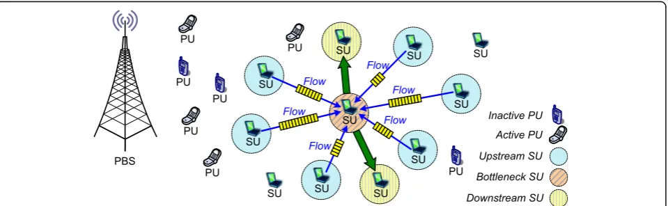
2 System model 2.1 Network model
Consider an underlay multi-hop CRANET coexisting
with a cellular primary network as depicted in Fig. 1,
wherein PUs can send their data traffic to a primary base station (PBS) via the licensed uplink channels.
We denote the set of uplink channels by ℋ= {ch1,
ch2,⋯,chϕ} where ϕ is the number of uplink
chan-nels. The uplink channel is either occupied by PUs or unoccupied. We employ the independent and
identi-cally distributed alternating ON-OFF process to
model the occupation time length of PUs in uplink channels. Specifically, the OFF state indicates the idle state where the uplink channels can be freely occu-pied by SUs. By performing spectrum sensing on all
the uplink channels periodically, S SUs leverage the
OFF state to access the unoccupied uplink channels
by PUs. Let V ¼ fv1;v2;⋯;vSg refer to the set of S
SUs. Each SU is equipped with two radio transceivers. One with a cognitive radio is used to opportunistic-ally access the uplink channels for transmissions of data packets. The other is used for exchange of con-trol signaling. Due to the randomness of data traffic and the dynamic behavior of PUs, we assume that the licensed uplink channels are available for usage by SU
vi with a probability of δi, for vi∈V. Based on the
aforementioned ON-OFF process, the occupancy
probability of uplink channel chξ by PUs is defined as
αξ/(αξ+βξ) [32], where αξ is a probability that uplink
channel ξ transits from OFF to ON state, andβξis
prob-ability that uplink channel ξ transits from ON to OFF
state, forξ= 1, 2,⋯,ϕ. It is assumed that SUs can
deter-mine the occupancy probability of uplink channels by PUs
through a priori knowledge of PUs’ activities and local
spectrum sensing. Owing to the mutually independent
oc-cupancy probability of uplink channelchξ, the probability
δiof uplink channels used by SUvican be expressed as:
δi¼
Yϕ
ξ¼1
1− αξ
αξþβξ !
: ð1Þ
Different from the assumption that time is divided into fixed time slots in a discrete way, we exploit the continuous time model to represent the operation duration of the CRANET. The continuous-time operation is confined to a predefined time interval [t0,T]. Useϑi(t) andz(t) to denote
the positions of SUvi, PUzat timet∈[t0,T], respectively.
LetRTandRIstand for the maximum transmission range
of SU and the interference range of PU, respectively.
With-out interference with PUs, a pair of SUvi and SUvj can
successfully communicate with each other on channel chξ
at timetonly if the Euclidean distance between SUviand
SUvjsatisfies‖ϑi(t)−ϑj(t)‖≤RTand when there is no any
PU z on channel chξ, i.e., ‖ϑi(t)−z(t)‖>RI and ‖ϑj(t)−
z(t)‖>RI, for vi;vj∈V andξ= 1, 2, ⋯, ϕ. In this context,
there exists a successful transmission link denoted byl(i,j)
from SUvito SUvjon channelchξat timet. For the sake
of conciseness, instant timetwill be restricted to the time
interval [t0,T] henceforth.
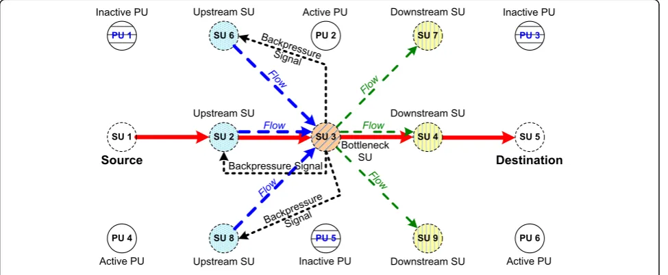
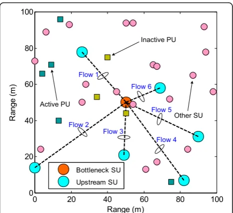
Under the constraint of successful transmission links, we assume that there are multiple different sessions from source SUs to destination SUs. Each session is associated
with a route from a source SU to a destination SU. Figure2
illustrates an example of logical topology of the underlay multi-hop CRANET, where a series of red solid line denote a session along a route from source SU1 to destin-ation SU5, which is one of the different routes. It is assumed that a session consists of several per-link flows
with elastic traffic. We use the term per-link flow to
describe a sequence of data packets with elastic traffic transmitted along a successful transmission link. With
regard to the route from source SU1 to destination SU5, data packets of a flow enter upstream SU2, travel via sin-gle hop, then converge at bottleneck SU3 and, finally, move to downstream SU4. We focus on a scenario that multiple different sessions converge at bottleneck SU, aiming to reinvestigate the cross-layer coupling between capacity supply by power control and rate demand by rate
control at upstream SUs. From Fig.2, the convergence of
multiple flows from upstream SU2, SU6, and SU8 via single hop may result in a possible congestion at bottle-neck SU3 when the offered data load exceeds the available capacity of SU3 due to a buffer overflow, although the amount of data packets has been delivered to downstream
SU4, SU7, and SU9. We assume that there areNflows of
elastic traffic along the successful transmission links from
Nupstream SUs to bottleneck SUvbvia single hop, forvb
∈V andN<S. Let VUP and N ¼ f1;2;⋯;Ng represent
the set ofNupstream SUs and the set of flows of elastic
traffic from N upstream SUs to bottleneck SU vb, for
VUP⊂V. For notational simplicity, the flow of elastic
traffic along link l(i,b) from upstream SU vi to
bottle-neck SUvbis described by flowi, for i∈N and vi∈VUP.
Assuming that flow i of elastic traffic along link l(i,b)
arrives as a Poisson process of flow arrival intensity λi
with a size drawn independently from a common
distri-bution of mean E½λi [33]. When Ψ(i,b)< 1, the
trans-mission link load, denoted by Ψ(i,b), induced by elastic
traffic along linkl(i,b)is equal to [33]:
Ψð Þi;b ¼
λiE½ λi Cð Þi;bð ÞP
; ð2Þ
where C(i,b)(P) denotes the capacity of link l(i,b), and P = {p1(t),p2(t),⋯,pN(t)} corresponds to the transmit
power vector ofNupstream SUs at timet. Here, we use
pi(t) to represent the instant transmit power of upstream
SUviat timet. Noticing that the transmit powerpi(t) of
upstream SUvican be adjusted in a continuous way but
is also limited by a maximum transmit power threshold denoted by pi, i.e., piðtÞ∈½0;piÞ. Based on elastic traffic
model for each flow, the expected duration Diof flow i
with sizeE½λiis given by [33]:
Di¼ E½ λi
Cð Þi;b ð Þ P 1−Ψð Þi;b: ð3Þ
Under spectrum underlay scenario, SUs can simultan-eously transmit with PUs but have to strictly control their transmit power to avoid interfering with coexisting PUs. Note that the simultaneous transmissions among SUs along a successful transmission link must be undertaken on the same channel, which will further incur the co-channel multiple access interference. We assume that the
simultan-eous transmissions amongNSUs along a successful
trans-mission link on channel chξcan be undertaken under the
CDMA-based medium access in the physical layer [34].
The reason for adopting the CDMA-based medium access model is that transmit power of upstream SU can be controlled to induce a different signal-to-interference-plus-noise ratio (SINR) of successful transmission link due to a
co-channel multiple-access interference [20, 35, 36]. In
principle, link capacity under this scenario cannot remain fixed but depends on SINR of successful transmission link
between a pair of SUs. Let SINR(i,b)(P) be the received
SINR of bottleneck SU vbalong linkl(i,b)on channel chξ.
Therefore, the capacity of linkl(i,b)from upstream SUvito
bottleneck SUvbcan be characterized by a global and
non-linear nonconvex function of the transmit power vector
and channel conditions as follows [20]:
Cð Þi;bð Þ ¼P Τ1 s
log21þχSINRð Þi;bð ÞP ; ð4Þ
where Τs is a symbol period and χ= −φ1/log2(φ2⋅ BER) is a constant processing gain factor with φ1 and φ2 depending upon an acceptable BER along with the specific modulation and coding scheme. We assume that a large-scale slow-fading channel model is adopted to describe the line-of-sight wireless transmission environment. In this case, channel gain is subject to distance-dependent power attenuation or log-normal shadowing. As for the practical non-line-of-sight scenario, we use a Rayleigh fading model, in which the channel gain is assumed to be independent exponentially distributed random vari-ables with unit mean [37]. Let G(i,b) and F(i,b) de-note the large-scale slow-fading and the Rayleigh fading channel gain of link l(i,b) from upstream SU vi to bottleneck SU vb, respectively. Thus, we have
the normalized Rayleigh fading channel gain E½Fði;bÞ
¼1 . By using the certainty-equivalent transmit power and interference power [34, 37], the received SINR of link l(i,b) at bottleneck SU vb can be
expressed as:
SINRð Þi;bð Þ ¼P
pið Þt Gð Þi;b IiþIpþn0;
ð5Þ
where n0 is the thermal noise power at bottleneck SU vb, Ip is the interference caused by the PBS, and
Ii is the aggregate power interference introduced by
other upstream SUs except upstream SU vi. The
ag-gregate power interference is given by Ii¼Pj∈N nipjð tÞGðj;bÞ. In what follows, we are targeted at the
line-of-sight wireless transmission environment with the large-scale slow-fading channel gain. How to apply the dynamic fast-fading or Rayleigh fading model under the non-line-of-sight scenario into the cross-layer optimization framework for CRANET will be our further work in the future. Under spectrum underlay scenario, the interference power constraint shall be imposed to protect active PUs’ communica-tions from harmful interference caused by all the upstream SUs. We assume that the interference measurement point is located at bottleneck SU vb
for convenience. Hence, the total interference caused by all the upstream SUs should be kept below the interference temperature limit ϖPBS at the interfer-ence measurement point of PBS:
X
i∈N
pið Þs Gð Þi;b ≤ϖPBS: ð6Þ
2.2 Predictable contact model
Considering that a contact is viewed as a communi-cation opportunity during which two adjacent SUs can communicate with each other, we move on to model the predictable contact between a pair of SUs from a priori available contact perspective. Based on
the insight into successful transmission link l(i,j) as
noticed earlier, an encounter e(i,j) is defined as an
ef-fective continuous transmission between SU vi and
SU vj with a certain duration, for vi;vj∈V. It is worth
pointing out that an encounter rests on the time of incidence and the duration of an effective
continu-ous transmission between a pair of SUs [38]. Let t0,
(i,j)
and Δt(i,j) represent the time of incidence and
the duration of an encounter e(i,j), respectively, for 0
<Δt(i,j)<T−t0. Therefore, an encounter e(i,j)
eð Þi;j ¼ vi;vj;t0;ð Þi;j;Δtð Þi;j
n o
: ð7Þ
Suppose that there existKencounters between SUviand
SUvjwithin a predefined time interval [t0,T]. In particular,
the ℓth encounter eðiℓ;jÞ between SUvi and SU vj with a
durationΔtðiℓ;jÞ, forℓ= 1, 2,⋯,K, is given as:
eð Þℓi;j ¼ vi;vj;tℓ0;ð Þi;j;Δtð Þℓi;j
n o
: ð8Þ
where t0ℓ;ði;jÞ refers to the time of incidence of the ℓth encounter eðℓi;jÞ. For mathematical tractability, we use the durationΔtðℓi;jÞin (8) to characterize theℓth encounter, i.e.,
eℓði;jÞ≜Δtℓði;jÞ. Thus, within time interval [t0,T], contactCði;jÞ between SUviand SUvjcan be rigorously regarded as the
set of all encounters, i.e.,Cði;jÞ¼ fe1ði;jÞ;e2ði;jÞ;⋯;eðKi;jÞgandj Cði;jÞj ¼
K. Note that the ℓth encounter eðℓi;jÞ in contact Cði;jÞ
can be referred to a random variable due to the uncer-tainty of communication opportunity between SU vi and
SUvj. In this way, we turn to employ a mathematical
statis-tics theory to attain the probability distribution ϒði;jÞ¼ f
ρði;jÞ
1 ;ρ
ði;jÞ
2 ;⋯;ρ
ði;jÞ
M g of contact C ði;jÞ
, which has been derived from Algorithm 1. In Algorithm 1, we introduce a coefficient M to denote the number of the subintervals, which is obtained by dividing interval [a,b] equally. According to the approximate derivation of the sample dis-tribution in mathematical statistics, coefficientMshould be reasonably assigned, depending on the number of encoun-ters of K. That is, when K≤100, coefficient M can range from 5 to 12. Obviously, it will be possible to measure the uncertainty of contactCði;jÞbetween SUviand SUvjby the
aid of the probability distributionϒ(i,j). Thus, by analyzing the statistical data of a priori available contact or all en-counters between a pair of SUs, it is implicitly understood that the contact can be in a sense predicted very accurately.
Table 1 summarizes the constrained relationship
between the number of encounters within subinterval
(dl−1,dl] and contact probability ρ
ði;jÞ
l in Algorithm 1,
for l= 1, 2,⋯, M. It is important to emphasize that the
probability distribution ϒ(i,j) belongs to a complete
probability distribution, i.e., PMl¼1ρðil;jÞ¼1 . Technically, the entropy paradigm is widely used for a measure of the uncertainty or randomness associated with a random
variable in information theory [39]. In order to
characterize quantitatively the probability distribution
ϒ(i,j)
, we put forward an entropy paradigm by using Shannon entropy theory to measure the uncertainty of
contact Cði;jÞ. Specifically, the entropy H(ϒ(i,j)) of the
probability distributionϒ(i,j)can be given as:
H ϒð Þi;j
¼−XM
l¼1
ρð Þi;j
l log2ρ
i;j ð Þ
l : ð9Þ
Based on Algorithm 1, it is obvious to find that
co-efficient M impacts the structure of the probability
distribution ϒ(i,j). Thereby, the entropy H(ϒ(i,j)) will
depend on the selection of coefficient M. Recall that
the probability δi of uplink channels used by SU vi
determines the stability of successful transmission link
l(i,j) or even the contact Cði;jÞ between SU vi and SU
vj due to the impact of PUs’ activities on the licensed
uplink channels. As such, we formally devise a contact affinity metric to describe the stability of the contact between a pair of SUs. Without losing
gener-ality, the contact affinity metric A(i,j) between SU vi
and SU vj within time interval [t0,T] is formally
Að Þi;j ¼H ϒð Þi;j
δiδj: ð10Þ
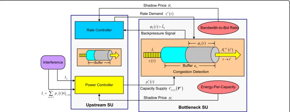
3 Problem formulation
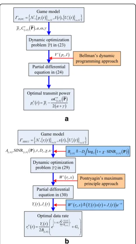
In this section, we intend to employ the differential game theoretic approach to formulate the PLPC problem in the physical layer and the HHCC prob-lem in the transport layer. Clearly, the distributed strategy needs to be used to design the cross-layer optimization framework for congestion and power control due to the lack of centralized control and global information under an underlay CRANET
sce-nario. As depicted in Fig. 3, each upstream SU will
serve as power and rate controller in charge of joint optimized allocation of transmit power in the phys-ical layer and data rate in the transport layer. Note that the change of power and rate will be continu-ous in time due to the fact that dynamic congestion and power control will be more realistic in a prac-tical environment.
3.1 Per-link power control in the physical layer
Given the channel conditions, the capacity of suc-cessful transmission link between a pair of SUs is a
nonconvex function of transmit power vector P. In
fact, increasing the link capacity on one link may
reduce the link capacities on other links because of
the mutual interference caused by SUs [20]. Instead,
each SU is expected to increase its transmit power to provide as much link capacity that per-link flow
requires [21]. However, this adjustment of power will
generate extra interference to other SUs. It is neces-sary to achieve an optimal per-link power allocation in the physical layer for upstream SUs to meet link capacity supply for all the flows. By letting the
trans-mit power of upstream SU vi equals the maximum
transmit power threshold, we can easily obtain the
maximum transmit power vector P¼ fp1;p2;⋯;pNg.
The transmission loss along link l(i,b) from upstream
SU vi to bottleneck SU vb on channel chξ is denoted
by η(i,b). Due to the line-of-sight wireless
transmis-sion environment with slow-fading channel model,
the transmission loss along link l(i,b) is represented
by η(i,b)= [c/(4πfξ⋅‖ϑi(t)−ϑb(t)‖)]2, where fξ is the
carrier frequency operating on channel chξ and c is
the speed of light. Therefore, the maximum transmit
power threshold pi of upstream SU vi along link l(i,b)
from upstream SU vi to bottleneck SU vb can be
for-mulated as:
pi¼p
ref
i;b ð Þ
ηð Þi;b
; ð11Þ
where prefði;bÞ is the received reference power at bottle-neck SUvbalong linkl(i,b). Given the maximum trans-mit power threshold pi, the capacity of link l(i,b)from upstream SUvito bottleneck SUvbcan be denoted by
Cði;bÞðPÞ. Owing to maximum transmit power
thresh-old, the value of power reduction for upstream SU vi
is equal to pi−piðtÞ. Recall that bits-per-Joule capacity
usually serves as a metric to measure the energy
Fig. 3Illustration of cross-layer optimization framework for hop-by-hop congestion control and per-link power control Table 1Constrained relationship from algorithm 1
Subinterval Number of encounters Contact probability
(d0,d1] qð1i;jÞ ρ
ði;jÞ
1 ¼q
ði;jÞ
1 =K
(d1,d2] qð2i;jÞ ρ
ði;jÞ
2 ¼q
ði;jÞ
2 =K
⋮ ⋮ ⋮
(dM−1,dM] qðMi;jÞ ρ
ði;jÞ M ¼q
efficiency of a communication system [40]. Consider-ing the impact of power reduction on energy efficiency with a link capacity constraint, energy efficiency for power reduction is formally defined as the power reduction achieved per capacity obtained under the maximum transmit power threshold. Thus, we plan to use the energy efficiency for power reduction to characterize a pricing factor of energy-per-capacity, aiming to design the revenue function of power reduc-tion for upstream SU. Given the maximum transmit power vector P, the pricing factorΦi(t) of
energy-per-capacity of upstream SU vi at time t can be formally
defined as:
Revisiting the pricing factor of energy-per-capacity of
upstream SUvi, we define the revenue function of power
reduction for upstream SU vi at timet by attaining the
product of the pricing factor together with power reduc-tion value, i.e., ΦiðtÞðpi−piðtÞÞ. Let ω denote the pricing
factor announced by upstream SUvito measure the cost
of the amount of aggregate power interference to PUs. The amount of aggregate power interference to PUs is
denoted by I(t). The cost function of aggregate power
interference to PUs for upstream SUviat timetis given
by ωI(t). Note thatI(t) is a dynamic variable influenced
by transmit power pi(t) of upstream SU vi and instant
levelI(t) within time interval [t0,T]. Thus, the aggregate
power interference I(t) can be characterized as a linear
differential equation given as:
dI tð Þ
where γ> 0 is a penalty factor of the amount of aggregate power interference and It0 is an initial aggregate power interference to PUs at time t0. Therefore, based on both revenue and cost func-tions as mentioned, the utility function Ui
1ðtÞ of up-stream SU vi at time t is given as:
Ui1ð Þ ¼t pi−pið Þt
Cð Þi;b P ðpi−pið Þt Þ−ωI tð Þ: ð14Þ
Note that utility function Ui
1ðtÞ is a continuously
differentiable function of pi(t) and I(t). We can find
that utility function in (14) mainly relies on pricing factor of energy-per-capacity in that the marginal effect on utility function stems from aggregate
power interference. As shown in Fig. 3, we
figura-tively define pricing factor Φi(t) as a shadow price
ℵi which is a function of transmit power of
up-stream SU vi. Our optimization objective is to
maximize utility function Ui1ðtÞ by choosing optimal
transmit power p#iðtÞ of upstream SU vi according discount factor a is an exponential factor between 0 and 1 by which the future utility must be multi-plied in order to obtain the present value under the underlying structure of differential game. Hence, utility function Ui
1ðtÞ has to be discounted by the factor e−aðt−t0Þ. Formally, the PLPC problem in the physical layer is formulated as a differential game model ΓPLPC: the upstream SUs in the PLPC problem as power controllers playing the game. Note that upstream SU vi stands for the ith player which is a rational
policy maker and acts throughout time interval [t0,T].
Set of strategies fpiðtÞgi∈N: The strategy of the
ith player refers to its instant transmit power limited by the maximum transmit power threshold, i.e., piðtÞ∈½0;piÞ.
State variableI(t): The state variable of theith player corresponds to the amount of aggregate power interference to PUs.
Set of utility functionsfUi1ðtÞgi∈N:Ui1ðtÞis the utility function of theith player. The objective of theith player is to maximize its utility function by rationally selecting optimal strategyp#iðtÞand optimal stateI#(t).
3.2 Hop-by-hop congestion control in the transport layer
Under the scenario that multiple flows from
upstream SU2, SU6, and SU8 via single hop
con-verge at bottleneck SU3 in Fig. 2, bottleneck SU3 is
due to buffer overflow. The amount of data packets
with elastic traffic in the buffer of bottleneck SU vb
at time t is denoted by φb(t). Given time t, t′∈[t0,
T] and t<t′, the amount of data packets φb(t) of
bottleneck SU vb within the time interval [t,t′]
satisfies the following iterative equation:
φbð Þ ¼t0 max min φbð Þ þt φt→t
packets accumulated in the buffer of bottleneck SU
vb and the amount of data packets that could be
delivered successfully to downstream SUs, respect-ively. Considering the constraint of the saturation value ^Lb of the buffer of bottleneck SU vb, we have
the buffer constraint φbðtÞ≤Lb^ to guarantee that bottleneck SU vb will not become the real
con-gested SU.
In the end-to-end congestion control, the conges-tion detecconges-tion informaconges-tion is piggybacked over data packets to the destination and then sent to the source through the acknowledgement packet from the destination. However, to feed the congestion detection information back to the upstream SU2, SU6, and SU8, bottleneck SU3 will generate a back-pressure signal to notify that the congestion occurs
as shown in Fig. 2. Compared with the end-to-end
mechanism, the backpressure signal is directly sent back to the corresponding upstream SUs from the bottleneck SU3 via single hop. Instead of passing the congestion detection information sent to the source in an end-to-end approach, the idea of hop-by-hop congestion control policy in this paper is
that upstream SU vi directly adjusts the data rate
ri(t) according to the backpressure signal of
bottle-neck SU vb when φbðtÞ>^Lb. Based on the radio
transceiver equipped by each SU, the backpressure signal is assumed to be transmitted through a com-mon control channel.
Given the received SINR of link l(i,b), we proceed
to derive the required bandwidth of upstream SU vi
for transmissions of data packets with elastic traffic.
According to Shannon’s capacity formula, the
required bandwidth of upstream SU vi can be
expressed by ri(t)/log2(1 +χ⋅SINR(i,b)(P)). We
fur-ther assume that bottleneck SU vb acts as a bidder
and pays for upstream SU vi to accommodate the
consumption of its network resources while
regulat-ing the data rate ri(t). We use x(t) to represent the
congestion bid that bottleneck SU vb is willing to
pay. We then characterize a bandwidth-to-bid ratio
aiming to describe the efficiency of bid with regard
to the required bandwidth, i.e., [ri(t)/log2(1 +χ⋅
SINR(i,b)(P))]/x(t). Hence, the cost function Ci(t) of
upstream SU vi at time t can be defined as:
Cið Þ ¼t rið Þ t
rið Þt=log21þχSINRð Þi;bð ÞP
x tð Þ Di: ð18Þ
We also use the bandwidth-to-bid ratio to figuratively
express the shadow price ℵi which is a function of the
data rate of upstream SUvi. Note that the shadow priceℵi
depends on an optimal per-link power allocation in the PLPC problem due to the constraint of the received SINR
of linkl(i,b)in bandwidth-to-bid ratio. In this way, we turn
our attention to the cross-layer coordination mechanism between capacity supply by power controller and rate
de-mand by rate controller based on shadow pricesℵiandℵi
as shown in Fig.3. By taking into account the stability of
the contact between a pair of SUs, we conclude thatA(i,
b)x(t) is the accumulated revenue obtained by upstream
SUvithat bottleneck SUvbneeds to pay. We also remark
that the congestion bid x(t) is a dynamic variable
influ-enced by rateri(t) as well as by instant level ofx(t) within
time interval [t0,T]. Accordingly, the congestion bid x(t)
can be formulated as a linear differential equation:
dx tð Þ
where xt0 is an initial congestion bid that bottleneck SU vb needs to pay at time t0 and υ is an average bid per rate, which is assumed to be a unit value for all the upstream SUs, i.e., υ= 1. Formally, based on both revenue and cost functions as stated before, the utility function Ui2ðtÞ of upstream SU vi at time t
can be expressed as:
Ui2ð Þ ¼t Að Þi;bx tð Þ−Cið Þ:t ð20Þ
Noticing that utility function Ui
2ðtÞ is also a
con-tinuously differentiable function of ri(t) and x(t).
Our optimization objective is to maximize utility
function Ui
2ðtÞ by choosing optimal data rate r#iðtÞ
of upstream SU vi while satisfying the buffer
con-straint at the same time:
Maximize:
where τ is a discount factor, for 0 <τ< 1. Similarly,
ΓHHCC ¼ N;frið Þt gi∈N;x tð Þ; Ui2ð Þt all the upstream SUs in the HHCC problem as rate controllers playing the game. Upstream SUvi is also known as theith player which
is a rational policy maker and act throughout time interval [t0,T].
Set of strategiesfriðtÞgi∈N: The strategy of theith player corresponds to its instant data rateri(t).
State variablex(t): The state variable of the
ith player refers to the congestion bid that bottleneck SUvbis willing to pay.
Set of utility functions fUi2ðtÞgi∈N: Ui2ðtÞ is the utility function of the ith player. The objective of the ith player is to maximize its utility function by rationally choosing optimal strategy r#iðtÞ and optimal statex#(t).
4 Optimal solution and distributed implementation
Conventionally, upstream SUs as players of the game are expected to act cooperatively and maximize their joint util-ity functions with fairness for players by constituting the collaborative coalition. As a result, the global optimization of transmit power and data rate will be attained through cooperation among players with group rationality, which has been recently reported in a cooperative bargaining
game [41]. However, each upstream SU is unwilling to
jointly adjust the power and rate because of the selfish be-havior in forwarding data packets. This is a natural idea due to the fact that the transmissions lead to the consumption of network resources of upstream SUs, such as energy and spectrum. Therefore, the cross-layer optimization frame-work for congestion and power control will be restricted to noncooperation scenario. In the noncooperative differential
game modelsΓPLPCandΓHHCC, theith player competes to
maximize the present value of its utility function derived
over time interval [t0,T]. For mathematical tractability, we
define the starting time of the differential game models
ΓPLPCandΓHHCCast0= 0 hereinafter, but the results can be
easily extended to more general cases.
4.1 Optimal solution toΓPLPC
For the noncooperation scenario, we formulate a
dynamic optimization problem ℙ1 to derive the optimal
solution to the noncooperative differential game modelΓPLPC
by taking into account the utility function maximization problem coupled with the linear differential equation con-straint in (13):
We aim at deriving an optimal solution to ℙ1 by
employing the theory of dynamic programming
devel-oped by Bellman [42]. Remark that the optimal solution
is also viewed as a Nash equilibrium solution toℙ1 if all
the players play noncooperatively. Here, we relax the
terminal time ofΓPLPC to explore whenTapproaches∞
(i.e.,T→∞) as an infinite time horizon. It is more
realis-tic to obtain the long-term optimal power allocation for upstream SUs due to spectrum underlay strategy with
cellular primary network. We use p#iðtÞto represent the
optimal solution to ℙ1 and assume that there exists a
continuously differentiable function Vi(pi,I) satisfying
the following partial differential equation:
aVip
4.1.0.1 Theorem 1 A vector of optimal transmit powerP# ¼ fp#1ðtÞ;p#2ðtÞ;⋯;p#NðtÞg of upstream SUs constitutes a Nash equilibrium solution to ℙ1 if and only if the optimal transmit power p#iðtÞof the ith player and the continuously differentiable function Vi(pi,I)can be formulated as follows:
p#ið Þ ¼t pi−ωC
From Theorem 1, we can observe that the exist-ence and uniqueness of the Nash equilibrium point
to ℙ1 are guaranteed under the constraint of
analyt-ical solution in (25) and (26). It is also revealed that
the optimal transmit power p#iðtÞhas been
character-ized by a fixed and unique value in (25). Evidently, Theorem 1 mathematically ensures the convergence
of p#iðtÞ to a Nash equilibrium point. The key point
to derive the optimal solution to the differential
game model ΓPLPC is illustrated with a block diagram
shown in Fig. 4a.
optimal transmit power p#iðtÞ of the ith player should follow the interference power constraint:
Y
i∈N
p#ið Þt ≤G1 Y
i∈N
ϑið Þt −ϑbð Þt
k k4: ð
27Þ
Proof: See Appendix 2.■.
Note that the optimal transmit power p#iðtÞ of the ith
player is fully constrained by the Euclidean distance
between upstream SUvi and bottleneck SU vbunder the
given channel model. Substituting forp#iðtÞwith its
expres-sion from Theorem 1 and taking into account the previous
expression of shadow priceℵi, we can easily rewriteℵias:
ℵi¼ ω
2ðaþγÞ: ð28Þ
Apparently, shadow priceℵitends to be a constant value
for all the upstream SUs. Although (25) and (26) offer an
analytical solution to ℙ1, it still remains to design an
algo-rithm to ensure fast convergence of the update of optimal transmit power. Therefore, we devise a distributed optimal transmit power update (OTPU) strategy given in
Algo-rithm 2 to update the optimal transmit power vectorP#for
upstream SUs. Similar to [43], shadow price ℵi in
Algo-rithm 2 needs to carefully be chosen to ensure fast
conver-gence of the update of instant transmit power p⊙i ðtÞ. It is
also noted that the update of instant transmit power p⊙i ðtÞ
for upstream SUvican be made locally according to its
opti-mal transmit power p#iðtÞ along with interference power
constraint.
4.2 Optimal solution toΓHHCC
For notational simplicity, we begin by defining a notation
B(i,b)≜ −Di/log2(1 +χ⋅SINR(i,b)(P)). For the
noncoopera-tion scenario, we formulate a dynamic optimizanoncoopera-tion
problemℙ2 to derive the optimal solution to the
nonco-operative differential game model ΓHHCC by taking into
account both the utility function maximization problem and the linear differential equation constraint in (19):
ℙ2 Maximize
rið Þt
:
Z T
0
Að Þi;bx tð Þ þBð Þi;b
r2
ið Þt
x tð Þ
e−τtdt
Subject to:dx tð Þ dt ¼x tð Þ−
X
i∈N
rið Þt ;
x tð0¼0Þ ¼x0:
ð29Þ
We turn to take advantage of the theory of maximum
principle developed by Pontryagin [42] to derive an optimal
solution or a Nash equilibrium solution to ℙ2. We further
use r#iðtÞ to represent the optimal solution toℙ2 and
as-sume that there exists a continuously differentiable function
−∂Wiðri;xÞ
For tractability, we introduce two extra introduced aux-iliary variablesYi(t) andJi(t) to characterizeWi(ri,x).
Spe-cifically, we defineWi(ri,x)≜(Yi(t)x(t) +Ji(t))e−τt.
4.2.0.1 Theorem 2 A vector of optimal data rateR#¼ f r#1ðtÞ;r#2ðtÞ;⋯;r#NðtÞgof upstream SUs constitutes a Nash equilibrium solution toℙ2if and only if the optimal data rate r#iðtÞof the ith player can be expressed as:
4.2.0.2 Proposition 2 The auxiliary variable Yi(t)in the
Nash equilibrium solution r#iðtÞ to ℙ2 can be further
Fig. 4The block diagram of the dynamic optimization problemsℙ1 andℙ2 coupled with their optimal solutions:aoptimal solution to ΓPLPCandboptimal solution toΓHHCC
Substituting B(i,b)≜ −Di/log2(1 +χ⋅SINR(i,b)(P)) into
(36), we can rewriteYi(t) as follows:
Let G3 be a constant number. Based on (31) and
(29), the optimal data rate r#iðtÞ and the optimal
From (38), we can see that the optimal data rate
r#iðtÞ is determined by both B(i,b) and auxiliary
vari-able Yi(t) under the received SINR SINR(i,b)(P) of
link l(i,b). Unfortunately, it is difficult to directly
ob-tain the relationship between SINR(i,b)(P) and r#iðtÞ
through an analytical derivation because Yi(t) cannot
be further simplified into a concise structure.
Thereby, given the channel gain G(i,b) of link l(i,b)
under the large-scale slow-fading channel model, we use the numerical simulations to validate the
effect-iveness of the optimal data rate r#iðtÞ of upstream
SU vi. We further remark that Theorem 2 and
Prop-osition 2 characterize the existence of the Nash
equilibrium point to ℙ2. It should be also admitted
that the optimal data rate r#iðtÞ has been formulated
as a fixed and unique value in (38) by using auxiliary
variable Yi(t) in (37). Correspondingly, Theorem 2
mathematically ensures the convergence of r#iðtÞ to a
Nash equilibrium point. The key point to derive the optimal solution to the differential game model
ΓHHCC is also illustrated with a block diagram
depicted in Fig. 4b. With the help of vectors R# and
P#
, shadow price ℵi can be calculated as:
ℵi¼
4.2.0.3 Proposition 3For the given vectorR#and vector P#
, a strict lower bound of shadow price ℵi can be
ap-proximately calculated as follows:
ℵi≥ log2 χ
from upstream SUvi to bottleneck SUvb. To guarantee
the constraint of the saturation value of the buffer of
bottleneck SU vb, we design a distributed algorithm to
obtain the optimal data rate update (ODRU) for
up-stream SUs as summarized in Algorithm 3, where R
= {r1(t),r2(t),⋯,rN(t)} denotes the data rate vector of N
upstream SUs at timet. A simple yet effective way to
lo-cally adjust the instant data rater⊙i ðtÞof upstream SUvi
is to employ the optimal data rater#iðtÞunder the
condi-tion of buffer constraint φbðtÞ≤L^b. Also, baseline rate
rbase
ði;bÞ in Algorithm 3 should be carefully chosen to ensure
4.3 Distributed implementation
So far, we have devised Algorithms 2 and 3 to sat-isfy the interference power constraint along with buffer constraint by locally adjusting the optimal transmit power and the optimal data rate, respect-ively. In what follows, we would like to describe the distributed implementation strategy to realize the cross-layer optimization framework for congestion and power control by jointly optimizing PLPC-HHCC simultaneously. In conclusion, the cross-layer optimization scheme for joint PLPC-HHCC design is implemented in a distributed manner as follows:
4.3.1 Shadow price
Update shadow price ℵiusing (28) and shadow price ℵi
using (40), respectively.
4.3.2 Power controller in the physical layer
For each upstream SU, we initially assign optimal
transmit power p#iðtÞ using (25) to update instant
transmit power p⊙i ðtÞat power controller. Due to the
interference power constraint in (6) to protect PUs,
p⊙i ðtÞ should satisfy the following distributed
power-update function when Pi∈NpiðtÞGði;bÞ>ϖPBS via
OTPU algorithm:
p⊙ið Þ ¼t p
⊙
ið Þ−ℵt ipi
; for 0<ℵi<1
p⊙ið Þ−t ð Þℵi−1pi
; for ℵi≥1
ð42Þ
4.3.3 Rate controller in the transport layer
For each upstream SU, we also initially assign optimal
data rater#iðtÞusing (38) to update instant data rater⊙i ð
tÞat rate controller. Owing to the buffer constraint φbðt
Þ≤^Lbto guarantee that bottleneck SUvbwill not become
congested, r⊙i ðtÞ should be subject to the following
dis-tributed rate update function when φbðtÞ>L^b via
ODRU algorithm:
r⊙i ð Þt ←r⊙i ð Þt −ℵirbaseð Þi;b: ð43Þ
4.3.4 Cross-layer coordination mechanism
With the aid of the updated power p⊙i ðtÞ, the link
capacity supply C(i,b)(P⊙) with respect to each
up-stream SU is regulated by power controller by using
(4) as shown in Fig. 3. The rate demand depends on
instant data rate r⊙i ðtÞ regulated by rate controller,
which is nonlinear function of instant transmit
power vector P⊙ according to (37) and (38).
5 Simulation results 5.1 Simulation settings
The simulation scenario is shown in Fig. 5, which
consists of one bottleneck SU and N= 6 randomly
more randomly distributed upstream SUs. Our sim-ulations pay more attention to evaluate the effect of the cross-layer optimization framework for conges-tion and power control on both optimal data rate and optimal transmit power of six different per-link flows. Different from the channel with carrier fre-quency of 890.4 MHz used by SUs, we assume that active PUs in simulation scenario occupy other
up-link channels from set ℋ.This can make possible
the successful transmissions of data packets from
upstream SUs to bottleneck SU. The probability δi
of uplink channels used by each SU is assumed to
be 0.65. The channel gain of link l(i,b) is defined
with large-scale slow-fading model, given by G(i,b)=
100g0‖ϑi(t)−ϑb(t)‖−4 [34], where the reference
chan-nel gain g0 is set to 9.7 × 10⁻⁴ [44]. We adopt a
processing gain factor χ= −1.5/log2(5BER) where
the target bit error rate is BER = 10−3 for multiple
quadrature amplitude modulation with a symbol
period of Τs= 52.5 μs. The thermal noise power at
bottleneck SU and interference caused by PBS are
assumed to be n0=−50 dBm and IP= 10 dBm,
re-spectively. In addition, the receiving reference power
at bottleneck SU is chosen as prefði;bÞ¼−37 dBm for
each upstream SU. With regard to the elastic traffic
modeled by Poisson process [32], the flow arrival
intensity is set to a normalized value λi= 125 bps
for each upstream SU, and the mean of flow size is
given as E½λi ¼2 Mbits . Under our differential
game models ΓPLPC and ΓHHCC, we choose the
pricing factor ω= 22, the penalty factor γ= 0.7, two
constant numbers G2= 5.5 and G3= 360.
Due to the lack of empirical data about available contact or all encounters between a pair of SUs, to
evaluate the uncertainty of contact Cði;bÞ along link
l(i,b), we assume that the minimum and maximum
values of encounter duration for all encounters
within contact Cði;bÞ is offered in Fig. 6. Note that
Flow i in Fig. 6 corresponds to contact Cði;bÞ along
link l(i,b), for i= 1, 2, ⋯, 6. We set the number of
subintervals in Algorithm 1 to M= 8 for all
up-stream SUs in that the number of encounters K
seems to be a lower value because of the short time interval in the simulations. In fact, game time or time interval is just set to [0, 5] s in the following simulations. Under this setting, the probability
distri-bution ϒ(i,b) of contact Cði;bÞ derived from
Algo-rithm 1 is assumed to comply with the contact
distribution as provided by Fig. 7.
The proposed OTPU algorithm for the PLPC problem is compared with the existing classical
distributed constrained power control (DCPC)
algorithm in [45]. The DCPC algorithm is a
SINR-constrained power control algorithm which distribu-tively and iteradistribu-tively searches for transmit power
updated from the ς th iteration to the (ς+ 1) th
it-eration. Let SINRtar
i denote the target SINR for
upstream SU vi to maintain a certain QoS
requirement. In the simulations, the target SINR can
be set as SINRtari ¼8 dB. Therefore, the iterative
function of transmit power update in the DCPC
al-gorithm with number of iteration ς= 0, 1, 2, ⋯ is
specifically given as [45]:
Fig. 6Comparison between minimum value and maximum value of encounter duration among different per-link flows
pðiςþ1Þ¼ min pi; SINR tar i
SINRð Þð Þςi;bð ÞP p ς ð Þ i
8 < :
9 =
;: ð44Þ
6 Results
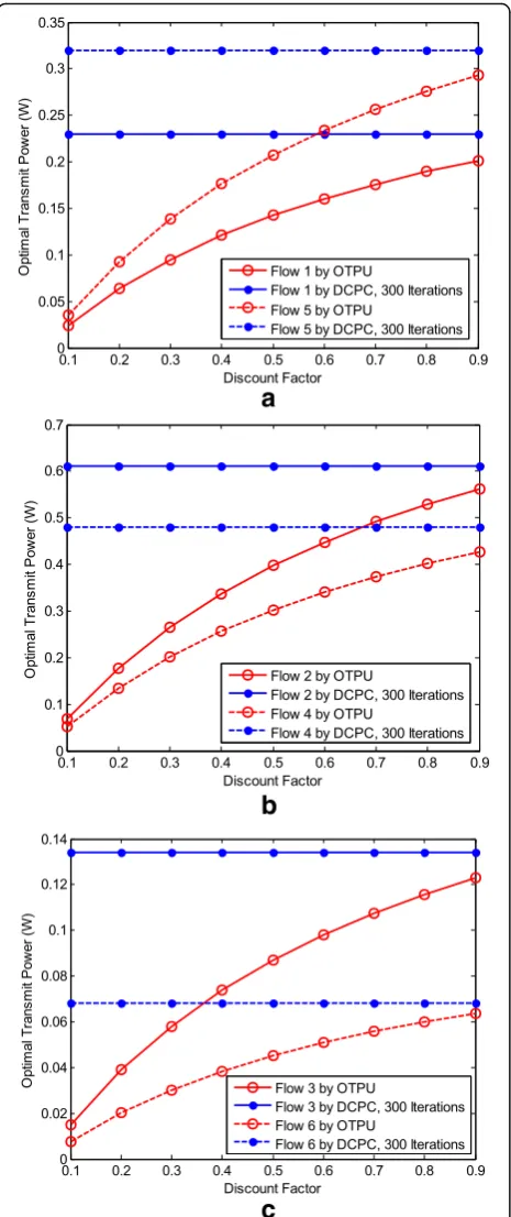
6.1 Performance of OTPU algorithm
Figure 8 shows the optimal transmit power
com-parison for six per-link flows between the OTPU
al-gorithm with the evolution of discount factor a and
the DCPC algorithm with ς= 300 iterations. This
figure clearly depicts that an increased discount fac-tor from 0.1 to 0.9 will increase the optimal trans-mit power of each flow under the OTPU algorithm. Apparently, this is a direct consequence of discount
factor a on the optimal transmit power according
to (25). However, it is observed that the optimal transmit power of each flow via the DCPC algo-rithm presents a fixed constant value. This is due to the fact that the optimal transmit power of each flow via the DCPC algorithm converges to an ex-pected equilibrium point after 300 iterations. It is worth mentioning that Theorem 1 mathematically makes the optimal transmit power of each upstream SU converge to a Nash equilibrium point distribu-tively. From the results, we can also see that the optimal transmit power of each flow by the OTPU algorithm is obviously lower than that of the DCPC algorithm. This can be explained by the fact that
DCPC algorithm gives rise to more power
consumption for maintaining a certain SINR for each upstream SU. However, the optimal transmit power of each flow based on the OTPU algorithm mainly depends upon the maximum transmit power threshold of upstream SU. On the other hand, the instant power level can be further reduced via the
change of discount factor a.
6.2 The impact of discount factor on optimal transmit power
Figure 9 illustrates the optimal transmit power
com-parison for six per-link flows via the OTPU algo-rithm under different discount factors. It is noted that the total interference caused by six upstream
SUs satisfies the interference temperature limit
ϖPBS= −10 dBm according to the constraint of (6).
As the discount factor increases, the optimal trans-mit power of six flows obtained by the OTPU algo-rithm will raise as well. As expected, the optimal transmit power of flow 6 can achieve the minimum transmit power level with approximately 50 mW, and the optimal transmit power of flow 2 can ob-tain higher transmit power level with the maximum value nearly 570 mW. However, the increasing rate of the optimal transmit power in regard to flows 6,
3, and 1 flattens out after discount factor a= 0.6.
The reason is as follows. Firstly, based on (25), the discount factor effect is in direct proportion to the optimal transmit power. One the other hand, with even higher Euclidean distance between upstream
SU and bottleneck SU, the maximum transmit power threshold will increase as well according to (11). Under the simulation scenario, the higher Eu-clidean distance of the successful transmission link of flow 2 leads to a higher transmit power level accordingly.
6.3 Optimal data rate performance of ODRU algorithm
Figure 10 exhibits the evolution of the optimal data
rate for six per-link flows obtained by the ODRU
al-gorithm versus game time t∈[0, 5]s under the
con-dition of discount factor τ= 0.2 and saturation value
^
Lb¼1 Mbps. From the results, we can see the
opti-mal data rate for six flows gradually increase with
the growth of game time t. Meanwhile, the optimal
data rate levels of six flows are very close from 0 to
4 s. When game time t is more than 4 s, the gaps
among the optimal data rate levels will be enlarged. This demonstrates that the optimal data rate has large values during the game time of the end
inter-val of the game. Under discount factor τ= 0.2, the
optimal data rate value of flow 2 is much larger than those of other flows with maximum value of 300 kbps, and the optimal rate of flow 6 has the lowest level within 50 kbps. It can also be observed that the optimal data rate of flow 2 yields significant performance gains than other flows under the condi-tion of the fixed discount factor. According to
satur-ation value L^b¼1 Mbps, we can observe that the
total data rate generated by six upstream SUs is
subject to the buffer constraint φbðtÞ≤^Lb such that
the instant data rate levels should not be adjusted through the ODRU algorithm.
a
b
c
Fig. 8Optimal transmit power comparison between our proposed OTPU algorithm and DCPC algorithm with 300 iterations under different per-link flows:aFlows 1 and 5,bflows 2 and 4, and
cflows 3 and 6
Figure11depicts the optimal data rate update compari-son for six per-link flows with the aid of the ODRU
algo-rithm on the condition of discount factor τ= 0.2 and
saturation value L^b¼490 kbps. It is implicitly revealed
that the total data rate caused by six upstream SUs fail to
guarantee the buffer constraintφbðtÞ≤^Lbsuch that the
in-stant data rate levels must be updated according to the ODRU algorithm. Hence, the evolution of the optimal data rate levels of six upstream SUs will enter the rate
up-date zone (i.e., shadow area in Fig.11) when the constraint
φbðtÞ>^Lb. From the results, we can see that the large
values of the optimal data rate have been considerably dwindled according to the distributed rate update function
in (41) when instant game timet= 4.3 s in order to meet
the buffer constraint of bottleneck SU.
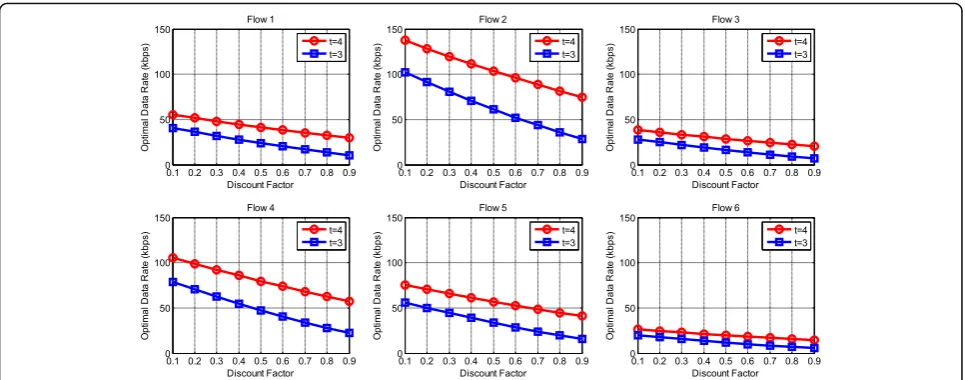
6.4 The impact of discount factor on optimal data rate
Figure 12 displays the evolution of the optimal data
rate for six per-link flows via the ODRU algorithm
versus discount factor τ under the condition of two
fixed instant game time point t (i.e., t= 3 and t= 4)
and saturation value ^Lb¼950 kbps. From the results,
we can see the total data rate generated by six up-stream SUs accommodates for the buffer constraint
φbðtÞ≤^Lb. It can be also observed that as the discount
factor increases from 0.1 to 0.9, the optimal data rate of six flows obtained by the ODRU algorithm will de-crease accordingly. The reason for this is that the utility function of each upstream SU must be
dis-counted by the factor e−τt at time t under the
differ-ential game structure ΓHHCC. As we expected, the
optimal data rate of flow 6 can obtain the minimum rate level within approximately interval [6, 26] kbps, and the optimal data rate of flow 2 can gain the max-imum value of data rate with nearly interval [30, 140] kbps. This can be explained by the fact that the higher Euclidean distance of the successful transmis-sion link of flow 2 will result in a higher transmit power level accordingly. This result of higher transmit power level of flow 2 will lead to the more link cap-acity supply. It implies that the upstream SU has the enough link capacity supply to achieve higher data rate in the proposed cross-layer optimization frame-work. Essentially, this signifies the importance of cross-layer coordination mechanism on the coupling between rate demand regulated by rate controller and capacity supply regulated by power controller.
7 Conclusions
In this paper, a distributed cross-layer optimization framework for congestion and power control for CRANETs under predictable contact has been pro-posed. Particularly, we introduced a predictable con-tact model by achieving the probability distribution of contact between any pair of SUs, aiming to measure the uncertainty of contact. Also, an entropy paradigm was presented to characterize quantitatively the prob-ability distribution of contact. We employed a differ-ential game theoretic approach to formulate the PLPC problem and the HHCC problem, and obtained the optimal transmit power and the optimal data rate of upstream SUs via dynamic programming and max-imum principle. To guarantee the interference power constraint for active PUs and the buffer constraint of bottleneck SU, we developed two distributed update algorithms to locally adjust optimal transmit power and optimal data rate of upstream SUs. Finally, we presented a distributed implementation strategy to construct the cross-layer optimization framework for
Fig. 11Optimal data rate comparison among six per-link flows through our proposed ODRU algorithm under saturation value^Lb¼490 kbps
congestion and power control by jointly optimizing PLPC-HHCC simultaneously and validated its per-formance with simulations. What we have discussed in this paper is the portion of foundation for the cross-layer optimization framework in CRANETs. In the future work, a joint objective function to achieve congestion and power control will be considered. Moreover, it will be interesting and important to in-vestigate a trade-off parameter as a whole to reflect the benefits of the proposed framework.
8 Appendix 1 8.1 Proof of Theorem 1
According to the dynamic optimization problemℙ1,
per-forming the maximization operation of the right hand
side of (24) with respect topi(t) yields the following
opti-mal solution:
Upon solving the differential equation in (46),Viðp#
i;IÞ
can be easily shown to be equivalent to the following equation:
Thus, an optimal transmit power p#iðtÞ which
consti-tutes a Nash equilibrium solution toℙ1 is given by:
p#ið Þ ¼t pi−ωC
9.1 Proof of Proposition 1
By substituting the vector of optimal transmit power P#
¼ fp#1ðtÞ;p#2ðtÞ;⋯;p#NðtÞg into the interference power constraint inequality in (6), we can obtain:
X
i∈N
p#ið Þt Gð Þi;b ≤ϖPBS: ð49Þ
After taking the logarithm of both sides of (49), we have:
Through rearranging terms, we have:
log2Y
i∈N
p#ið Þ þt log2Y
i∈N
Gð Þi;b ≤ log2ϖPBS: ð51Þ
By taking into account the large-scale slow-fading channel model to describe the wireless transmission
environment, the channel gain of link from upstream SU
where g0 is a reference channel gain at a distance of 100 m [34]. We substitute G(i,b) in (52) into (51) and
Thus, (53) can be rewritten as follows:
Y
have the solution of (27).
10 Appendix 3 10.1 Proof of Theorem 2
According to the dynamic optimization problem ℙ2, by
performing the maximization operation of the right
hand side of (30) with respect tori(t), we can obtain:
Hence, this completes the proof.
11 Appendix 4
11.1 Proof of Proposition 2
Owing to the symmetric form of Yi(t) and Yj(t) in (57),
we can immediately denote (57) by Riccati equation:
dYið Þt
As such, the form of (59) can be rearranged by differ-ential equation as:
make equation in (61) an exact form by multiplying it on both sides of (61). Here, we can easily obtain:
ℑðYið Þ;t tÞ ¼
. By integrating (64)
and (65) with respect toYi(t), we have:
G2is a constant number. Upon solving (66) as follows:
t−1
Solving the above equation in (68) with respect to

![Figure 12and saturation valueoptimal data rate of flow 6 can obtain the minimumrate level within approximately interval [6, 26] kbps,and the optimal data rate of flow 2 can gain the max-imum value of data rate with nearly interval [30,140] kbps](https://thumb-us.123doks.com/thumbv2/123dok_us/922862.1111848/19.595.57.290.87.265/figure-saturation-valueoptimal-minimumrate-approximately-interval-optimal-interval.webp)