ISSN(Online): 2319-8753 ISSN (Print): 2347-6710
I
nternational
J
ournal of
I
nnovative
R
esearch in
S
cience,
E
ngineering and
T
echnology
(An ISO 3297: 2007 Certified Organization)
Vol. 5, Issue 6, June 2016
Comparitive Simulation of a Centrifuger Bowl
by Using Composite Laminates
Kondru Nagendra Babu1, D.Manoj Kumar 2 , P.Sai Kishore 3
Assistant Professor, VNR Vignan Jyothi Institute of Engineering and Technology, Hyderabad, A.P India1
P.G. Student, Department of Mechanical Engineering, R.V.R &J.C Engineering College, Guntur, A.P India2
P.G. Student, Department of Mechanical Engineering, VNR College of Engineering, Ponnur, Guntur, A.P India3
ABSTRACT: A decanter centrifuge separates solid materials from liquids in slurry and therefore plays an important role in wastewater treatment .This paper deals with a mathematical and comparative computational simulation of the bowl of the Centrifuge Decanter to improve the efficiency . A bowl is the key parts of centrifuge which contain scroll assembly which subject to more wears, stress and material deformation in separating the solids and water The outcome of this project was to improve the performance of bowl which contains scroll for solid removal operation. A composite laminate has been added to bowl and comparative stress simulation was done on bowl with and without adding composite laminate.
KEY WORDS: composite laminate, factor of safety, hydrostatic stress, carbon epoxy, tensile test
I. INTRODUCTION
A centrifuge is a device that uses centripetal force to separate mixtures of solids and liquids [1]. Centrifuges can be used to separate almost any mixture, ranging from drilling mud to fish oil. A decanter centrifuge is a particular type of centrifuge that uses a scroll conveyor in the bowl to allow for continuous separation of mixtures with up to three different phases. A. The performance of a decanter can be quantified in several ways, including, concentrate clarity, solids dryness, or solids recovery fraction. While the decanter centrifuge utilizes modern manufacturing technology to improve balance and increase operating speed, the materials and design have remained relatively unchanged since the modern decanter was developed in the 1970s. While work has been completed to develop variations of decanter centrifuges, there has been little research on improving the current design by applying new materials and scientific analysis methods. There is a clear opportunity to develop the existing design of a decanter centrifuge to reduce power consumption and improve performance.
TABLE-1
Specifications of HC 350 decanter centrifuge
Inside bowl diameter 347mm
Bowl length 1050 mm
Maximum bowl speed 3476rpm
Acceleration 2349*g
Relation of bowl length and diameter
3:1
ISSN(Online): 2319-8753 ISSN (Print): 2347-6710
I
nternational
J
ournal of
I
nnovative
R
esearch in
S
cience,
E
ngineering and
T
echnology
(An ISO 3297: 2007 Certified Organization)
Vol. 5, Issue 6, June 2016
II. PRODUCT TRANSPORT
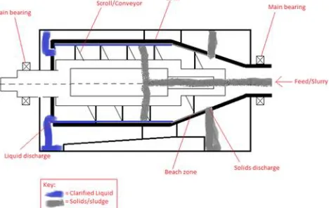
Once the solids have settled against the bowl wall they are transported to the solids discharge ports by the scroll conveyor shown in figure.1. A large normal force acts on the bowl wall due to the high centripetal acceleration. This high normal force, combined with the constant relative motion gives rise to friction , it is this friction that consumes a large amount of power. The power consumed by friction is a function of the coefficient of friction between the settled solids and the machine components. The coefficient of friction is a function of material, surface finish, product, and product wetness [4].Product transport is the process of the scroll conveyor moving the solids that have settled against the bowl wall to the solids discharge ports. Understanding the product transport is important in the design and operation of any centrifuge as it strongly influences product quality and consumes a substantial portion of the total power required by the centrifuge. The product transport is influenced by many design features and operating parameters. The operating parameters include those controllable during operation, such as flow rate, bowl and differential speed, pool depth, and feed temperature. Other operating parameters that were explored include flow paths, cake dryness, hydrostatic pressure, and lifting of the solids. Design features that are discussed here include the bowl geometry .These design features are fixed during design and manufacturing and cannot usually be varied during operation. The primary resistance to product transport is Coulomb friction between the settled solids, also known as the cake, and the bowl wall and scroll blade faces.
Figure 1: Descriptive view of decanter centrifuge IIa. BOWL RADIUS
The bowl speed is one of the most important operating parameters of a centrifuge as it is related to the centripetal acceleration in the cylindrical section by the expression
a = ω2*r0 (1) Where r0 is inner radius of the bowl in the cylindrical section.
Higher bowl speeds result in higher centripetal acceleration, which results in faster separation and higher clarity of the centrate. The bowl speed has varying effects on different types of solids; for crystalline solids the dryness increases with speed,. While increasing the speed and bowl radius leads to higher output. It also increases the transport torque and power consumption due to the increased normal force on the bowl wall. Generally the radius of bowl to be 175mm. By adding the composite layer of 8 mm which is made of carbon epoxy cause increase in centripetal acceleration. it can also be act as resistance to crystalline solids as dryness increases with speed, so composite bowl reduce wear
III. COMPOSITE LAMINATE
ISSN(Online): 2319-8753 ISSN (Print): 2347-6710
I
nternational
J
ournal of
I
nnovative
R
esearch in
S
cience,
E
ngineering and
T
echnology
(An ISO 3297: 2007 Certified Organization)
Vol. 5, Issue 6, June 2016
majority of the load and is the major contributor to the composite material properties. The resin helps to transfer load between fibres, prevents them from buckling and binds the materials together. The range offered is based upon composite sheets produced by stacking carbon fibre fabrics one upon another and then infusing the stack with resin under vacuum [10].
IV .MATERIAL DESCRIPTION
The material commonly used for bowl is ALSI 314 stainless steel. The composition and material properties of stain less steel are shown in (table 2,3&4) .Later a carbon epoxy laminate of 8 mm is added to bowl
TABLE-2: Composition of ALSI 314 stainless steel
component c cr fe mn ni p
Wt% 0.25 26 47 2 22 0.045
TABLE-3: Material properties ALSI 314 stainless steel
density 7.8g/cc
Ultimate tensile strength
689mpa
Yield strength 345mpa
Modula’s of elasticity
200mpa
Specific heat capacity
15.1u/mm
Thermal conductivity
17.5w/m-k
TABLE-4: Carbon epoxy properties
density 1.6g/cc
Coefficient of thermal expansion(ln) 2.1*10-6k-1
Coefficient of thermal expansion(tr) 2.1*10-6k-1
Young’s modulus(ln) 70gpa
Young’s modulus(tr) 70gpa
Tensile yield strength(ln) 600mpa
Tensile yield strength(tr) 600mpa
Compressive yield strength(ln) 570mpa
Compressive yield strength(tr) 570mpa
volume fraction of fibre 50
Ex 0.3
ISSN(Online): 2319-8753 ISSN (Print): 2347-6710
I
nternational
J
ournal of
I
nnovative
R
esearch in
S
cience,
E
ngineering and
T
echnology
(An ISO 3297: 2007 Certified Organization)
Vol. 5, Issue 6, June 2016
IV b. FIBRE ORIENTATION
For carbon epoxies the strength and stiffness parameters depends up on angle of orientation of fibre. For the bowl
carbon epoxy laminate structure can be used which is easy to manufacture the carbon epoxy laminate. In
general, composite laminates are assemblies of layers of fibrous composite materials which can be joined to provide required engineering properties, including in-plane stiffness, bending stiffness, strength, and coefficient of thermal expansion. In this paper carbon epoxy laminate was considered with 4 layers each of 2mm thickness and each layer have different orientations of fibre.
V. COMPOSITE ANALYSIS
Three composite laminates were considered for analysis with same carbon fibre orientation angles (00, ±450) and same
resin but differ in arrangement of layers. Since with arrangement of layers stiffness of material varies Analysis was done using finite element analysis [11]. Factor of safety of the composite was determines to optimize the best laminate
Va. Composite laminate-1
This laminate structure has four layers. The first layer has fibre orientation with an angle of -450.second and third layer has fibre orientations 00.Fourth layer has fibre orientation of+450 which were carried out with the help of ANSYS software by considering shell element 281 widely used for laminate analysis The arrangement of layers as shown in 2).composite analysis was done for layers and results of maximum stress and minimum stress shown in (figure-3).
Fig.2: Sequential Arrangement of layers of laminate1 which was done in ANSYS software by considering each layer thickness 2 mm
Fig.3: stress distribution of laminate-1. the composite material subject to maximum stress of 0.25e10 n/m 2and
minimum stress of0.24e9 n/m2
Vb. Composite laminate-2
ISSN(Online): 2319-8753 ISSN (Print): 2347-6710
I
nternational
J
ournal of
I
nnovative
R
esearch in
S
cience,
E
ngineering and
T
echnology
(An ISO 3297: 2007 Certified Organization)
Vol. 5, Issue 6, June 2016
Fig-4:sequential Arrangement of layers of laminate-2 which was done in ANSYS software by considering each layer of thickness 2mm
Fig-5: stress distribution of laminate-2. the composite material subject to maximum stress of 0.4e10 n/m 2and minimum
stress of 0.14e9 n/m2
V c. Composite laminate-3
This laminate structure has four layers. The first layer has fibre orientation with an angle of -00.second and third layer has fibre orientations -450,0 0 Fourth layer has fibre orientation of +450 The arrangement of layers as shown in (figure-6).composite analysis was done for layers and results of maximum stress and minimum stress shown in (figure-7).by changing the arrangement of layers there is chance of increase in stability of laminates to withstand transverse and shear force
ISSN(Online): 2319-8753 ISSN (Print): 2347-6710
I
nternational
J
ournal of
I
nnovative
R
esearch in
S
cience,
E
ngineering and
T
echnology
(An ISO 3297: 2007 Certified Organization)
Vol. 5, Issue 6, June 2016
Fig.7: Stress distribution of laminate-3 the composite material subject to maximum stress of 0.10e9 n/m 2and minimum
stress of 0.28e7 n/m2
VI. MATERIAL TESTING
A flat panel was produced to test the tensile strength, toughness, the composite. Two panels, measuring 500 mm x 500
mm were made carbon fibres were inserted with specific angles as mentioned above (±45 0,0 0) by hand lay up. The
fibre orientations are given in (Table 5). There are more fibres on the 0° axis as the stress in the hoop direction is larger than in the axial direction. The 45° layers are included for shear strength and they are required to support the bolts that are included in later models. five tensile specimens were cut in each of two directions 00 and 45 0. By using universal testing machine the ultimate tensile strength and young’s modulus of the material were found and platted on the (table.5)
TABLE-5: Tensile strength and Young’s modulus for the tensile test specimens cut from flat panel
450 00
sample Uts (mpa) E (gpa) sample Uts (mpa) E(gpa)
1 598.74 66.75 1 588.6 67.43
2 598.63 68.96 2 590.4 68.27
3 599.35 69.37 3 589.3 66.26
4 598.0 69 4 586.4 66
5 599 69.93 5 589.5 68.23
average 598.74 68.8 average 588.4 67.23
From the above table we can see that there is a slight variation in average values between 00 and 450. So ultimate tensile strength and young’s modulus place major role in designing the system for determining factor of safety and to simulate failure criteria’s .It is always better to consider the maximum values so ultimate tensile strength of 600 mpa and young’s modulus of 70 gpa has been preferred. Factor of safety for the constructed laminates has been found out by considering the ultimate tensile strength
VIa .FACTOR OF SAFETY
Factor of safety is a term describing the capacity of material beyond exceptational loads, essentially
Fos =yield stress / maximum stress (2)
ISSN(Online): 2319-8753 ISSN (Print): 2347-6710
I
nternational
J
ournal of
I
nnovative
R
esearch in
S
cience,
E
ngineering and
T
echnology
(An ISO 3297: 2007 Certified Organization)
Vol. 5, Issue 6, June 2016
VII. COMPOSITE BOWL
The original design of a decanter centrifuge used either steel or stainless steel for the majority of components. Some of the other materials used in decanters include titanium, nickel, and alloyed aluminium . There were several potential benefits to redesigning the bowl using different materials, including:
• Increased lifespan of components due to higher wear resistance
• Reduced power consumption and product destruction due to a lower coefficient of friction between the settled solids and the bowl wall
• Lower bearing loads, leading to extended life and lower power consumption • Potential to increase operating speed due to higher specific strength materials
The design process of the new composite bowl for a Centrifuge Decanter is presented in this project. The chapter includes a description of the current design, design specification, load calculations, concept generation, material selection, material testing, final design, and the manufacturing process. the bowl which is made up of ALSI 316 steel of 347mm diameter. Composite laminate .3 which is found to have better factor of safety is attached to internal layer of bowl. .For determining the loading conditions acting on bowl consider a case study were decanter separating poly vinyl chloride and water and various variables has been found out an plotted in (table6).
Table-6: Case study variables for Centrifuge Decanter separating PVC
Solid density (ρs) 1400 kg/m3
Liquid density (ρl) 1000 kg/m3
Solid flow mass rate (ms) 1.2 t/h
Liquid flow mass rate (ml) 10.8 t/h
Total mass flow rate (mt) 12 t/h
Bowl radius including composite layer (r0) 173.6 mm
Liquid discharge radius (rdl) 132.6mm
Solid discharge radius (rds) 122mm
VIII. PROBLEM STATEMENT
The wear of the bowl can be very high, in some applications the centrifuge may need to be refitted within six months. When the scroll flights and the inside surface of the bowl become too worn the centrifuge is no longer able to operate effectively. For this composite laminate of 8 mm thickness is added If the wear of the material is able to be decreased, the interval between overhauls can be increased, leading to less plant downtime and decreased plant maintenance cost. Foreign materials, such as pieces of steel or stones, can enter the centrifuge; therefore, the new material must be able to withstand these passing through.
IX. MODELLING
ISSN(Online): 2319-8753 ISSN (Print): 2347-6710
I
nternational
J
ournal of
I
nnovative
R
esearch in
S
cience,
E
ngineering and
T
echnology
(An ISO 3297: 2007 Certified Organization)
Vol. 5, Issue 6, June 2016
Fig.8: Geometry model of bowl in CATIA V5 by considering dimensions as bowl inside diameter 355mm and cone angle140
Fig.9: Mesh model of bow with a total of 5802 nodes and 828 elements with the help of ANSYS software
X. LOAD CALICULATIONS
In this section the loads acting on the bowl are theoretically calculated. There are five main loads that give rise to appreciable stress within the bowl: hydrostatic hoop stress, hydrostatic axial stress, hoop stress from bowl mass, axial stress from solids transport, and shear stress from solids transport .Among them bowl subject to hydraulic stress was maximum compare to other stresses. This project deals with hydraulic stress
Xa. HYDRAULIC HOOP STRESS (σh h)
The hoop stress in a pressure vessel is equal to the pressure acting on the wall multiplied by the radius r0 and divided by
the wall thickness. The hoop stress in the bowl as a function of the operating and design variables is
σh h = r0 *ρs *ω2 (r02 – ri2 )/2t (3)
ri = radius of scroll hub =91.5mm
r0= bowl radius including composite laminate =355mm
X b. HYDROSTATIC AXIAL STRESS (σA h)
The axial stress due to hydrostatic pressure is the axial load divided by the cross sectional area of the bowl and is equal to
σA h = (ρs *ω2/4π r0t) * (r03/3 - ri2 r0+2 ri2/3) (4) The hydraulic hoop stress for bowl is 14.6Mpa and hydrostatic axial stress is 20.3Mpa
XI. FINITE ELEMENT ANALYSIS
Comparative analysis was done in this project by considering load calculations . Initially structural analysis was done on bowl without adding composite laminate. Results obtained shown (figures 9 &10).Later structural analysis was don on bowl by adding composite laminate of thickness8mm.The results were plotted on (fugures11 &12)
X1a.ANALYSIS OF BOWL BY ADDING COMPOSITE LAYER
ISSN(Online): 2319-8753 ISSN (Print): 2347-6710
I
nternational
J
ournal of
I
nnovative
R
esearch in
S
cience,
E
ngineering and
T
echnology
(An ISO 3297: 2007 Certified Organization)
Vol. 5, Issue 6, June 2016
Fig.9: Stress distribution of bowl when subject to hydrostatic stress .At the end of cone section of bowl subject to
maximum stress of 90621 n/mm2due to feed accelerator
Fig.10: deformation of bowl when subject to hydrostatic stress where Maximum deformation of 1.14e-7 m at the end of cylindrical section
X1b.ANALYSIS OF BOWL WITH OUT ADDING COMPOSITE LAYER
After performing structural analysis of bowl by adding composite layer it is recommended to perform structural analysis of bowl without adding composite layer. stress distribution and deformation of bowl was shown in (figures11&12)
Fig.11: Stress distribution of bowl when subject to hydrostatic stress .At the end of cone section of bowl subject
ISSN(Online): 2319-8753 ISSN (Print): 2347-6710
I
nternational
J
ournal of
I
nnovative
R
esearch in
S
cience,
E
ngineering and
T
echnology
(An ISO 3297: 2007 Certified Organization)
Vol. 5, Issue 6, June 2016
Fig.12: deformation of bowl when subject to hydrostatic stress where Maximum deformation 4.235e-7m at the end of cylindrical section
XII. CONCLUSIONS
Table-7: results of static structural analysis
parameters Bowl without composite Bowl with composite
Maximum vonmises stress 79813pa 90621pa
deformation 4.235e-7 1.14E-7
Depending up on type of solids and hours of operation centrifuge bowl must be able to withstand maximum
amount of stress. Bowl with composite can be able to withstand maximum amount of stress and subject to low deformation
Composite laminate -3 with fibre orientation 00 , -450 , 00 +450 posses maximum factor of safety and laminate
could withstand maximum amount of stress 0.287e7n/m2 (fig -7)
It is optimum to add composite laminate to the bowl to withstand maximum amount of stresses during product
transport of solids
XIII. ACKNOWLEDGEMENTS
The author would like to thank “Hindustan Coca-Cola. Beverages Pvt. Ltd” for its constructive scientific effort and support in helping the author to produce this research paper
REFERENCES
[1] Pasol. L., Dousset, C.Huyghe, “New centrifuge pond level control system handles variable feeds. Filtration & Separation”, 47 (5), 18-21. [2] Minaker. V.E., “Prospects For Future Developments in Screw-Conveyor Sedimentation Centrifuges”. Chemical and Petroleum Engineering, 1995, 31
(3), 8-13.
[3] Reif. F., Stahl, W., “Transportation of moist solids in decanter centrifuges”. Chemical Engineering Progress, 1989, 85 57-67. [4] Leung, W.W.F., Torque requirement for high-solids centrifugal sludgede watering. Filtration & Separation, 1998, 35 (9), 883-887.
[5] Fainerman. I.A., Paramonov. I.A., “ Calculation of the power of centrifuge drives required for the acceleration of suspensions”. Chemical and Petroleum Engineering, 1985, 21 (4), 184-186.
[6] Leung, W.W.F., “Industrial Centrifugation Technology”. McGraw-Hill, New York,1998. [7] Journal of Composite Materials 1998; 32: 1247-1272