Bandwidth Improvement of Microstrip Patch
Antenna Using Partial Ground Plane &
Circular Slot
Amrit Chakraborty 1, Saikat Paul2, Sayan Basu 3, Mritunjoy Mondal 4, Tarun Yadav 5, Shirshendu Pandit6
U.G. Student, Department of Electronics & Communication Engineering, SDET-Brainware Group of Institutions,
Barasat, Kolkata, India1-5
Assistant Professor, Department of Electronics & Communication Engineering, SDET-Brainware Group of Institutions,
Barasat, Kolkata, India6
ABSTRACT: In wireless communication system antenna plays vital role. Therefore, there is demonstrated need that antenna used in any communication system should be low weight, low profile, low cost, smaller in dimension and conformity. A Microstrip patch antenna fulfills all these requirements. In this paper A large number of methods have been suggested, which can reduce the limitations of the antenna, thus improving the performance, with no deviations in the basic advantages of the antenna The area of research interests are like changing the geometrical dimensions of the antenna, especially changing the dimensions of the ground plane of the antenna using partial ground, introducing radius slot in our circular patch.
KEYWORDS: Microstrip antenna, narrowband, circular polarization, enhanced bandwidth, high return loss, coaxial feed, Radiation Pattern, Antenna efficiency, Radiation Efficiency, bandwidth enhancement, circular slot, partial ground.
I. INTRODUCTION
In recent years, the current trend in commercial and government communication systems has been to develop low cost, minimal weight, low profile antennas that are capable of maintaining high performance over a large spectrum of frequencies. This technological trend has focused much effort into the design of micro strip (patch) Antennas. The approach of the microstrip antenna enjoys all the advantages of printed circuit technology.
Apart from these all benefits, the microstrip antenna has some limitations too, that is, they suffers from narrow bandwidth operation, low efficiency, surface wave excitations and poor end fire radiations. The Q-factor of the antenna can be improved by considering a thick substrate, but that will lead to more power delivered to the surface waves, This results in unwanted power losses.
Fig. 1. Circular Microstrip Patch Antenna
II. RELATED WORK
In [fig 4] a microstrip patch antenna is designed for a wireless communication application, which is operating at a Frequency of 2.25 GHz. In this paper a RMSA is designed having substrate material as Rodger 5880 (εr=2.2) & height
of substrate is 0.5 cm. A 200 MHz bandwidth is obtained by using this design. A coaxial probe feed RMSA design is presented in [fig 2(b)]; this antenna can be used in radar application & also have application in Geotechnical, Engineering, Environmental.
III. DESIGNING OF ANTENNA
The designing of Microstrip patch antenna depends upon three parameters which are dielectric constant of substrate Thickness of the substrate and dimension of patch. Depending on the dimension, the operating frequency, radiation Efficiency, directivity, returns loss is influenced. Due to presence of fringing fields between patch and ground plane, Geometrical dimensions of patch are smaller than electric dimension.
Design parameters of proposed circular microstrip patch antenna are as following:
Size of substrate(x,y) 10 cm,9cm
Thickness of substrate 0.5cm
Radius of patch 1.5cm
Feeding point (x,y) -0.5cm,0cm
Parameters of microstrip patch antenna
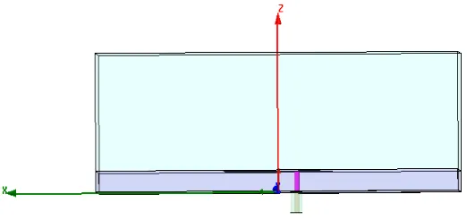
2(a) stack up and feeding mechanism
Fig 2(b) indicates side view of antenna.
After feeding we create a circular patch of 1.5 cm radius. Now the design looks like this.
Fig 2(b) indicate top view of antenna.
2(b) top view Fig 2(c) indicates side view of antenna.
2(c) side view
Fig 3(a) indicate antenna figure before reducing ground plane.
3(a) before reduce ground plane
Fig 3(b) indicate antenna figure after reducing ground plane.
3(b) after reduce ground plane
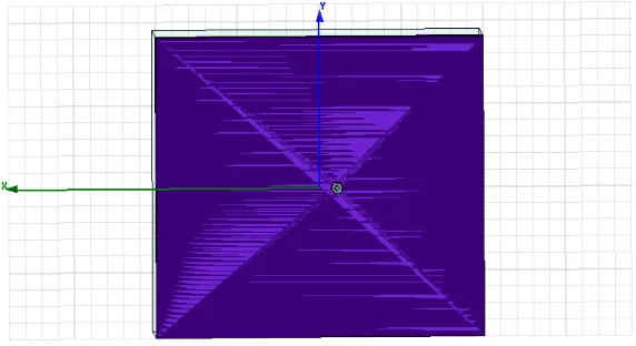
Fig 4 indicate final diagram of proposed antenna.
4 top view of final antenna
IV. SIMULATION AND RESULTS
On analyzing the antenna with circular patch, the corresponding Rectangular Plot was obtained, from which, it was found that the antenna gave a Bandwidth of 140 MHz at 2.25GHz resonating frequency. The Rectangular Plot for the Return loss value of the antenna is given below:
5(a) rectangular plot of circular patch antenna
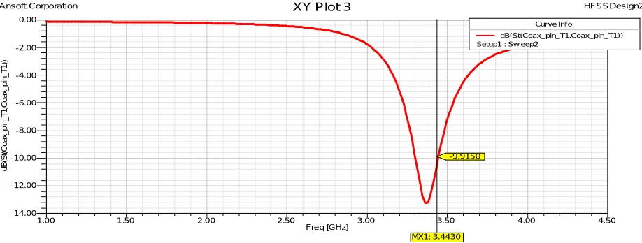
Now to increase bandwidth we use partial ground technique now bandwidth 160MHz with same resonating frequency. The Rectangular Plot for the Return loss value of the antenna is given below:
1.00 1.50 2.00 2.50 3.00 3.50 4.00 4.50
Freq [GHz] -14.00 -12.00 -10.00 -8.00 -6.00 -4.00 -2.00 0.00 d B (S t( C o a x _ p in _ T 1 ,C o a x _ p in _ T 1 ))
Ansoft Corporation XY Plot 3 HFSSDesign2
-9.9150
MX1: 3.4430
Curve Inf o
5(b) Rectangular plot of circular patch antenna with partial ground
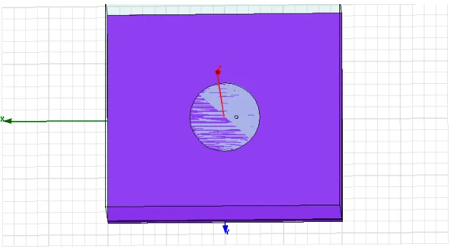
Now we add 0.70 cm radius slot in our circular patch so bandwidth greatly improved now BW: 200 MHz The Rectangular Plot for the Return loss value of the antenna is given below:
5(c) Rectangular plot of circular patch antenna with partial ground & circular slot.
1.00 1.50 2.00 2.50 3.00 3.50 4.00 4.50
Freq [GHz] -15.00 -10.00 -5.00 0.00 d B (S t( C o a x _ p in _ T 1 ,C o a x _ p in _ T 1 ))
Ansoft Corporation XY Plot 1 HFSSDesign2
-9.9638
MX1: 3.4266
Curve Inf o
dB(St(Coax_pin_T1,Coax_pin_T1)) Setup1 : Sw eep2
1.00 1.50 2.00 2.50 3.00 3.50 4.00 4.50
Freq [GHz] -25.00 -20.00 -15.00 -10.00 -5.00 0.00 d B (S t( C o a x _ p in _ T 1 ,C o a x _ p in _ T 1 ))
Ansoft Corporation XY Plot 2 HFSSDesign2
-10.0870
MX1: 3.2216
Curve Inf o
The Radiation pattern of the antenna is given below:
5(d) radiation pattern patch antenna with partial ground & circular slot.
V. CONCLUSION
We can analyze that by using partial ground & introducing circular slot in the patch we can achieve modified bandwidth. The antenna band width is increased up to 14.2% and it resonates at 2.25GHz resonance frequency. Along with band width antenna directivity, efficiency and radiation pattern also improved. The proposed antenna has high bandwidth which can be used for wireless Communication of high data rate Compared with normal Circular patch antenna.
REFERENCES
1. Pammi Kumari, Shyam Sunder Sonkar, Akhilesh Kumar, R. K. Prasad“Circular Microstrip Patch Antenna Using Coaxial Feed for S-Band Application”, IJRET, Vol.11, pp.94-107, 2009.
2. Deepender Dabas, Abhishek “Design of Circular Micro strip Patch Antenna with different Slots for WLAN & Bluetooth Application”,IJERT, Vol. 2 Issue 9, September – 2013.
3. Munna Singh Kushwaha, Chandan, R.K. Prasad “Improvement of Bandwidth of Microstrip Patch Antenna by Multiple Notches” , Advances in Communication and Control Systems ,2013.
4. Siju J Thomas, Mehajabeen Fatima “Bandwidth Improvement of Microstrip Patch Antenna using Partial Ground Plane” , IJERT, Vol. 4 Issue 05, May-2015.
5. Shirshendu Pandit , Supriya Jana , Geetali Chakrabarty “International Journal of Engineering Trends and Technology”, International Journal of Engineering Trends and Technology , IJETT ,VOL-8,NO-4.
-14.30 -13.60 -12.90 -12.20
90 60 30
0
-30
-60
-90
-120
-150
-180
150
120
Ansoft Corporation Radiation Pattern 1 HFSSDesign2
Curve Inf o
dB(rETotal) Setup1 : LastAdaptive Phi='0deg'