Scholarship@Western
Scholarship@Western
Electronic Thesis and Dissertation Repository
4-21-2014 12:00 AM
Characterization of Fine Powders and Development of Processes
Characterization of Fine Powders and Development of Processes
for Powder Coatings
for Powder Coatings
Jing Fu
The University of Western Ontario
Supervisor Dr. Jesse Zhu
The University of Western Ontario Joint Supervisor Dr. Hui Zhang
The University of Western Ontario
Graduate Program in Chemical and Biochemical Engineering
A thesis submitted in partial fulfillment of the requirements for the degree in Doctor of Philosophy
© Jing Fu 2014
Follow this and additional works at: https://ir.lib.uwo.ca/etd
Part of the Polymer Science Commons, and the Process Control and Systems Commons
Recommended Citation Recommended Citation
Fu, Jing, "Characterization of Fine Powders and Development of Processes for Powder Coatings" (2014). Electronic Thesis and Dissertation Repository. 2026.
https://ir.lib.uwo.ca/etd/2026
This Dissertation/Thesis is brought to you for free and open access by Scholarship@Western. It has been accepted for inclusion in Electronic Thesis and Dissertation Repository by an authorized administrator of
CHARACTERIZATION OF FINE POWDERS AND DEVELOPMENT OF PROCESSES FOR POWDER COATINGS
(Thesis format: Integrated Article)
By
Jing Fu
Graduate Program in Engineering Science Department of Chemical and Biochemical Engineering
A thesis submitted in partial fulfillment of the requirements for the degree of
Doctor of Philosophy
The School of Graduate and Postdoctoral Studies Western University
London, Ontario, Canada
ii
Powder coating process is a dry coating technology which utilizes resin based powders
(medium particle size between 35 to 60 µm) as coating materials. It is green and
economical since the use of harmful solvents can be avoided and most of the overspray
materials can be recycled. However, the poor appearance provided by powder coatings
has always been a big drawback. Fine powder coating (medium particle size less than 30
µm) was first introduced in around 2001. It was able to provide much smoother coating
finishes due to the smaller powder particles. However, fine powder coating has still not
been widely used yet because of the unstable fluidization performances. This thesis study
comprehensively investigated the fluidization performances and various powder processes
of both regular and fine powder coatings. Moreover, it developed numbers of new
techniques and methods for powder coating productions and applications.
The flowability of a powder that represented the ability of the powder to be handled used
to be assessed by the medium particle size and the amount of small particles in the powder.
Yet, experiments conducted in this study disclosed that the conventional methods to
characterize the flowability of the fine powders were not accurate, since the flowabllity
results scattered with respect to the medium particle size and the amount of small particles.
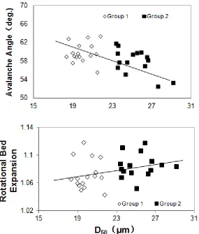
Instead, the parameter, span, which represents the particle size distribution, was found to
have a much more accurate correlation with the flowability of the fine powders.
In addition, the material processes of fine powder coatings were investigated. The current
processes are designed to aim for the maximum production throughput. Nevertheless, it
lacks of the control for the particle size distribution which is crucial for fine powders. The
study developed novel designs of grinder and cyclone to reduce the produced powder
iii
grinder. On the other hand, the new cyclone design could also provide significant
reduction in the span of the powder. At the same time, it could still retain reasonable
collection efficiency.
The study also investigated the electrical property of the fine powder coatings according
to the application of the electrostatic spraying. The influence of moisture content of the
fine powder coatings was discovered. The experiments indicated that additional moisture
on the surfaces of the fine powder particles could significantly reduce the resistivity of the
powder so as to enhance the transfer efficiency. However, the regular powder coating had
less significant reduction in the resistivity after humidification. As a result, it received less
significant improvement on the transfer efficiency. The experiment also disclosed that the
improvement on the transfer efficiency of the powder coating was progressive with
respect to the increases of the humidification level.
Moreover, a multi-electrode corona spray gun with alternative charging pattern was
developed for improving the Faraday Cage resistance. The results obtained from the
experiments indicated that the new spray gun could improve the Faraday Cage resistance
of the corona spraying with the fine powder sample for various gun voltages. On the other
hand, the improvement of the Faraday Cage resistance with regular powder sample was
not noticeable until a high gun voltage of -90 kV was reached. The transfer efficiency
provided by the new spray gun with fine powder sample was comparable to a
conventional spray gun, whereas, the transfer efficiency with regular powder sample was
iv
powder coating were revised. By utilizing the invented dry blending catalyst, pre-curing
problems of the low-cured powder coatings could be solved. Moreover, experimental
results indicated that the new technique could provide similar curing performances as the
conventional low-cure powder sample. More importantly, the new technique could also
provide much improved coating quality and much prolonged shelf life of the low-cured
powder coating. On the other hand, the bonding problem of the metallic color powder
coatings was solved by incorporating the liquid bonder in the blending of powder particles
and the metallic pigment. Experiment found that the same concentration of the metallic
pigment measured in both pre-sprayed powders and post-sprayed powder could be
achieved by using the new technique. It indicated that the liquid bonder could provide
good bonding strength between the metallic pigment and powder particles so as to
eliminate the separations between the two materials during spraying.
Nowadays, finer powder coatings become more popular to use, since better coating films
has to provided for fulfilling higher aesthetic requirements in the applications. The
discoveries of the thesis study contributed to the development of the powder coating
technology. It provided useful suggestions to the understanding of the fine powder
flowability. Furthermore, it also developed several new methods and techniques for
improving the current processing of powder coatings.
v
Dr. Jesse Zhu and Dr. Hui Zhang provided full supervision and guidance to this PhD thesis study.
Related publications:
1. Title: Improvement on the first pass transfer efficiency of fine polymer coating powders for corona spraying process
Authors: Jing Fu, Hui Zhang, Jesse Zhu
All the research works were conducted by Jing Fu under the supervision of Dr. Hui
Zhang and Dr. Jesse Zhu. The final version of the manuscript was published on
vi
In the beginning, I would like to express my greatest gratitude to Dr. Jesse Zhu, a
professor in the Department of Chemical and Biochemical Engineering of Western
University and a fellow of Canadian Academy of Engineering. Along my PhD study,
Dr. Zhu provided invaluable guidance and enormous encouragement to me. The
appreciation was extended to Dr. Hui Zhang, a research professor in the Department of
Chemical and Biochemical Engineering of Western University. I had been working
with him closely on a daily basis. His detailed instructions and suggestions were vital
to the success of this thesis study. I had been deeply infected by his enthusiasm and
precision of research.
I am also grateful to Dr. Andy Sun, a professor in the Department of Mechanical and
Material of Western University, Dr. Charles Xu, a professor in the Department of
Chemical and Biochemical of Western University, and Cedric Briens, a professor in
the Department of Chemical and Biochemical of Western University. They provided
useful knowledge as well as helpful recommendations to this thesis study from the
aspects of their expertises.
In addition, I would like to thank Mr. Bin Xi, the technical manager of Azuratech Fine
Powder Coating (MianYang, China) and Ms. JiangPing Yu, the general manager of
Azuratech Fine Powder Coating (MianYang, China) for giving me the opportunity to
visit their factory site.
Moreover, my appreciations continue to Michael Zhu and Jianzhou Wen for their
vii
analysis tests on the experimental samples; to Meysaa Hussein and Hanmeng Qi for
their assistances on conducting a part of the experiment works of my PhD study; to
my colleagues, Danni Bao, Dangchen Xue, Rezwana Yeasmin, Mohammad Bhuiyan,
Nicholas Hou, Qingliang Yang, Xi Zhang, Shan Gao, Yijun Dong, Tang Li, Jiangshan
Liu and Jingsi Yang for the enjoyments of working with them.
Furthermore, I would like to thank OGS (Ontario Graduate Scholarship) and QEII
(Queen Elizabeth II Graduate Scholarship) for providing the financial supports to
myself as well as my PhD study.
Particularly, I want to deliver the deepest thankfulness to the most important people in
my life: my father Shilin Fu, my mother Xueqin Liu, my daughter Yvonne Fu, my
wife Yifan Chu, my mother-in-law Chungui Li and the other family members. Their
viii
ACKNOWLEDGEMENTS ... vi
TABLE OF CONTENTS ... viii
LIST OF FIGURES ... xii
LIST OF TABLES ... xvii
LIST OF ABBREVIATIONS AND SYMBOLS ... xx
CHAPTER 1: GENERAL INTRODUCTION ... 1
1.1 Introduction ... 1
1.1.1 Powder ... 1
1.1.2 Powder Coating ... 1
1.2 Challenges and Opportunities of Powder Coating Application ... 2
1.3 Research Objectives and Overview ... 3
1.4 Thesis Structure ... 5
1.5 Major contributions ... 7
CHAPTER 2: LITERATURE REVIEW ... 10
2.1 Powder ... 10
2.1.1 Powder Characterizations ... 10
2.1.3 Flow Additive for Cohesive Powders ... 12
2.2 Powder Coating Technology ... 13
2.3 Manufacturing Processes for Powder Coatings ... 15
2.4 Application of Powder Coatings ... 25
ix
CHARACTERIZATION OF FINE POWDER COATINGS ... 37
3.1 Introduction ... 37
3.2 Materials and Methods... 39
3.2.1 Flowability Measurements ... 39
3.2.2 Particle Size Measurement ... 41
3.3 Results and Discussion ... 42
3.4 Conclusion ... 49
CHAPTER 4: DEVELOPMENT OF A NOVEL CLASSIFYING CYCLONE FOR REDUCING PARTICLE SIZE DISTRIBUTION OF FINE POWDER COATINGS ... 53
4.1 Introduction ... 53
4.2 Numerical Modeling ... 56
4.4 Experimental Study... 71
4.4.1 Materials and Methods ... 72
4.4.2 Results and Discussion ... 75
4.4.3 Observations ... 84
4.5 Conclusions ... 85
CHAPTER 5: THE INFLUENCE FROM A REVISED GRINDER DESIGN ON THE PARTICLE SIZE DISTRIBUTIONS OF FINE POWDER COATINGS ... 89
5.1 Introduction ... 89
5.2 Materials and Methods... 91
5.3 Results and Discussion ... 93
x
CHAPTER 6: FURTHER STUDY ON THE INFLUENCE OF HUMIDITY ON IMPROVING FISRT PASS TRANSFER EFFICIENCY OF POWDER
COATINGS DURING CORONA CHARGE SPRAYING... 105
6.1 Introduction ... 105
6.2 Materials and Methods... 107
6.3 Results and Discussion ... 114
6.3.1 Effect of Humidity on the Electrical Properties of the Powders ... 114
6.3.2 Spraying Test ... 116
6.3.4 Effects of the Humidity on Powder Flowability ... 120
6.3.5 Effect of Humidity on Coating Quality ... 123
6.4 Conclusion ... 126
CHAPTER 7: IMPROVEMENT ON THE FARADAY CAGE RESISTANCE BY REVISED CORONA CHARGE SPRAY GUN ... 129
7.1 Introduction ... 129
7.2 Materials and Methods... 131
7.3 Results and Discussion ... 135
7.3.1 Fine Powder Coating ... 135
7.3.2 Coarse Powder Coating ... 142
7.4 Conclusion ... 148
CHAPTER 8:DEVELOPMENT OF THE DRY BLENDING TECHNIQUE FOR PROCESSING LOW-CURE POWDER COATINGS... 154
8.1 Introduction ... 154
xi
8.3.1 Influences of the DBC on Coating Qualities ... 160
8.3.2 Optimization of the DBC ... 162
8.3.3 Evaluation of the DBC Low-cure powder coating ... 167
8.4 Conclusion ... 174
CHAPTER 9:DEVELOPMENT OF THE COLD BONDING TECHNIQUE FOR PROCESSING METALIC COLOR POWDER COATINGS ... 176
9.1 Introduction ... 176
9.2 Materials and Methods... 178
9.3 Results and Discussion ... 182
9.3.1 Spraying test ... 182
9.3.2 Observations of the Bonding of Powder Particles and Metallic Pigment184 9.3.3 Observations of Metallic Effect ... 186
9.4 Future Work ... 187
9.5 Conclusion ... 188
CHAPTER 10: GENERAL DISSCUSSION ... 191
CHAPTER 11: GENERAL CONCLUSIONS ... 198
APPENDICS ... 202
Appendix I Modeling Setup and Boundary Conditions for the Cyclone Simulation 202 Appendix II Experimental data ... 203
Appendix III Related Publications ... 219
xii
Figure 2-1: Geldart’s chart for powder classifications ... 11
Figure 2-2: A typical hot extrusion process ... 16
Figure 2-3: A grinder mill for powder coating ... 17
Figure 2-4: A classifier for powder coating ... 19
Figure 2-5: Forces acting on particle within a rotating classifier (Top view) ... 20
Figure 2-6: A typical cyclone for collecting powder coatings ... 21
Figure 2-7: Diagram of grade efficiency curve characteristics. ... 23
Figure 2-8: A typical air classifying mill (ACM) operation ... 24
Figure 2-9: A thermal spraying gun ... 25
Figure 2-10: A fluidized bed application of powder coating ... 26
Figure 2-11: A corona charge spraying ... 28
Figure 2-12: A tribo charge spraying ... 29
Figure 3-1: An example of particle size distribution ... 41
Figure 3-2: Flowabilities of the fine powder samples with respect to D50 ... 43
Figure 3-3: Flowabilities of the fine powder samples with respect to D10 ... 45
Figure 3-4: Flowabilities of the fine powder samples with respect to the span ... 46
Figure 3-5: Flowability with respect to the span less than 1.45 ... 47
Figure 4-1: The cyclone structure. ... 54
Figure 4-2: Forces acting on small particles (left) and large particles (right) on a cross-section of the cyclone ... 55
Figure 4-3: Diagram of grade efficiency curve characteristics. ... 56
xiii
Figure 4-6: Insert to provide the secondary air inlet with air guiders. ... 59
Figure 4-7: Measured ACM dimensions of the original cyclone used in this study ... 60
Figure 4-8: Meshed cyclone model by GAMBIT: ... 61
Figure 4-9: Velocity vectors of the air in Model O ... 63
Figure 4-10: The axial velocity contour in Model O on the XZ plane ... 64
Figure 4-11: The axial velocity at the solids outlet in Model O ... 65
Figure 4-12: Velocity vectors of the air in Model SA ... 66
Figure 4-13: The axial velocity contour in Model SA on the XZ plane ... 67
Figure 4-14: The axial velocity at the solids outlet in Model SA... 68
Figure 4-15: Velocity vectors of the air in Model SAG ... 69
Figure 4-16: The axial velocity contour in Model SAG on the XZ plane ... 70
Figure 4-17: The axial velocity at the solids outlet in Model SAG ... 71
Figure 4-18: The scheme of the experimental process ... 72
Figure 4-19: An example of particle size distribution ... 74
Figure 4-20: Comparisons of D10, D90 and the span with respect to D50 with the straight-vane classifier installed ... 76
Figure 4-21: The collection efficiency of cyclones with straight-vanes classifier installed ... 78
Figure 4-22: Comparisons of D10, D90 and the span with respect to D50 for angled-vane classifier blade set-up ... 81
Figure 4-23: The collection efficiency of the cyclones with the angled-vane classifier installed ... 83
xiv
Figure 5-1: Proposed grinder design for grinding of fine powders ... 90
Figure 5-2: The blade of the grinder ... 91
Figure 5-3: Comparison between original and modified blades ... 92
Figure 5-4: The medium particle size with respect to the grinding duration ... 94
Figure 5-5: D10 and D90 of the produced fine powders with respect to D50 ... 95
Figure 5-6: The span of the produced fine powders with respect to D50 ... 96
Figure 5-7: A typical mechanical mill for powder coating manufacture – The air classifying mill (ACM) ... 97
Figure 5-8: The 1st modification of the grinding element of the lab scale ACM ... 99
Figure 5-9: The measured spans of the powders ground by the lab scale ACM with the 1st modified grinding elements ... 99
Figure 5-10: The 2nd modification of the grinding element of the lab scale ACM ... 100
Figure 5-11: The measured spans of the powders ground by the lab scale ACM with the 2nd modified grinding elements ... 100
Figure 5-12: The 3rd modification of the grinding element of the lab scale ACM ... 101
Figure 6-1: A demonstration of charged particles on a metal substrate ... 109
Figure 6-2: Development of back ionization ... 110
Figure 6-3: Schematic diagram of the apparatus setup for powder humidification .... 111
Figure 6-4: The changes in moisture content of the humidified powders ... 114
Figure 6-5: Changes in resistivity of the humidified powders ... 116
Figure 6-6: FPTE from the preliminary experiment (Method of using humidified fluidizing air) ... 117
xv
the fluidized air ... 119
Figure 6-9: FPTE of powder C3 in the full scale experiment (method of humidified fluidizing air) ... 120
Figure 6-10: The moisture content of the powders after stagnated in an extreme humid environment ... 121
Figure 6-11: Visual inspection of the powders in different exposure time. ... 122
Figure 6-12: SEM images of the powder particles (humidification of 60 minutes) .... 124
Figure 6-13: SEM images of the coating surfaces (humidification of 60 minutes) .... 125
Figure 7-1: The particle size distributions of the powder samples ... 131
Figure 7-2: The revised corona gun ... 132
Figure 7-3: The charging scheme of the revised corona spray gun ... 133
Figure 7-4: The Panel geometry and the panel size for Faraday Cage measurements 134 Figure 7-5: TheFaraday Cage and transfer efficiency for –30kV (Fine powder) ... 136
Figure 7-6: An illustration of corona quenching ... 137
Figure 7-7: The Faraday Cage and transfer efficiency for –60kV(Fine powder) ... 138
Figure 7-8: The Faraday Cage and transfer efficiency for –90kV (Fine powder) ... 139
Figure 7-9: The current density pattern with one or two gun electrodes ... 140
Figure 7-10: The effects of electrode positions of the new spray gun ... 141
Figure 7-11: The comparison between the original and the new spray gun with the gun voltage of –90kV and the spraying duration of 8s ... 142
Figure 7-12: The Faraday Cage and transfer efficiency for –30kV (Coarse powder) . 143
Figure 7-13: The Faraday Cage and transfer efficiency for –60kV (Coarse powder) . 145
xvi
Figure 8-1: Comparison between the original nano silica (left) and the coated nano silica (right) under the TEM ... 157
Figure 8-2: The images of the powder particle with nano additive on the surface taken from the SEM ... 158
Figure 8-3: Image identifications of different coating surfaces ... 160
Figure 8-4: The images of the coating by samples with different curing performances ... 166
Figure 8-5: The comparison of the coating quality between DBC, extruded and control samples ... 169
Figure 8-6: Dynamic run on the DSC of the three samples with heating rate of 20oC/min. ... 171
Figure 8-7: Images of the samples extracted during the shelf life tests ... 173
Figure 9-1: The influence of the blending time on the metallic effect of the coating . 180
Figure 9-2: SEM image of the metallic pigment during blending ... 181
Figure 9-3: Change in the content of the aluminum measured from the coated powder comparing with the according virgin powder ... 184
Figure 9-4: Images of the metallic powder coatings taken from SEM observations .. 185
xvii
Table 4-1: The list of the cyclones tested in the experiment ... 72
Table 6-1: Particle sizes of the test powders ... 108
Table 6-2: Flowabilities of the powders during humidity exposure ... 123
Table 8-1: The influences of DBC on the gloss of the coating... 161
Table 8-2: The influences of DBC’ on the gloss of the coating ... 162
Table 8-3: Curing performances of the control sample and the samples with different dosage of promoter A and B for 15 minutes of curing period at 170oC ... 164
Table 8-4: Comparisons of the control sample, the DBC sample and extruded sample with various curing temperatures. ... 168
Table 8-5: Comparisons of the control sample, the DBC sample and extruded sample with various curing time. ... 170
Table 9-1: Samples of the metallic powder coating prepared by the new technique for the spraying test ... 182
Table 9-2: The measured content of the samples from spraying tests ... 183
Table A-1: Measured particle sizes and flowabilities of fine powder coating samples (Group 1 samples) ... 203
Table A-2: Measured particle sizes and flowabilities of fine powder coating samples (Group 2 samples) ... 204
Table A-3: The performances of various cyclones with straight-vanes classifier installed ... 205
Table A-4: The performances of various cyclones with angled-vanes classifier installed ... 206
xviii
fluidization with humidified air ... 207
Table A-7: The measured resistivity of the powder samples with respect to the fluidization time (humidification in a fluidized bed) ... 208
Table A-8: The FPTE of powder A with 30%RH of the fluidization air ... 209
Table A-9: The FPTE of powder A with 50%RH of the fluidization air ... 209
Table A-10: The FPTE of powder A with 70%RH of the fluidization air ... 210
Table A-11: The FPTE of powder A with 90%RH of the fluidization air ... 210
Table A-12: The measured performances of an ordinary powder spray gun (with fine powder coating) ... 211
Table A-13: The measured performances of a modified powder spray gun (with fine powder coating and spraying duration of 4s) ... 211
Table A-14: The measured performances of a modified powder spray gun (with fine powder coating and spraying duration of 8s) ... 212
Table A-15: The measured performances of a modified powder spray gun (with fine powder coating and spraying duration of 12s) ... 212
Table A-16: The measured performances of an ordinary powder spray gun (with coarse powder coating) ... 213
Table A-17: The measured performances of a modified powder spray gun (with coarse powder coating and spraying duration of 4s) ... 213
Table A-18: The measured performances of a modified powder spray gun (with coarse powder coating and spraying duration of 8s) ... 214
Table A-19: The measured performances of a modified powder spray gun (with coarse powder coating and spraying duration of 12s) ... 214
xix
different electrode locations at gun voltage of -60kV (with fine powder coating;
spraying duration of 8s; distributor voltage of 4V) ... 215
Table A-22: The measured performances of a modified powder spray gun with different electrode locations at gun voltage of -90kV (with fine powder coating;
spraying duration of 8s; distributor voltage of 4V) ... 216
Table A-23: The measured performances of a modified powder spray gun with
different electrode locations at gun voltage of -30kV (with coarse powder coating;
spraying duration of 8s; distributor voltage of 4V) ... 216
Table A-24: The measured performances of a modified powder spray gun with
different electrode locations at gun voltage of -60kV (with coarse powder coating;
spraying duration of 8s; distributor voltage of 4V) ... 217
Table A-25: The measured performances of a modified powder spray gun with
different electrode locations at gun voltage of -90kV (with coarse powder coating;
spraying duration of 8s; distributor voltage of 4V) ... 217
xx Abbreviations:
AVA Avalanche Angle
AOR Angle of Repose
RBER Rotational Bed Expansion Ratio
D10, 50, 90 particle diameter, where 10, 50 or 90 volume % of the powder smaller than the
diameter (µm)
VOC Volatile Organic Compound
SEM Scanning Electron Microscope
DSC Differential Scanning Calorimetry
DBC Dry blended catalyst
ACM Air classifying mill
Symbols:
A Hamaker constant
Atc Cross-sectional area of the test cell for the resistivity measurements (m2)
H The separation distance between two particles (µm)
R Particle radius (µm)
W Powder weight (g)
η Collection efficiency (%)
r Powder feeding rate (g/s)
Ep Electrostatic field strength of powder coating (V/m)
R Resistance of powder coating (ohm)
FPTE First Pass Transfer Efficiency (%) ρp Resistivity of powder coating (ohm-m)
μ Velocity (m/s)
J Corona current (A/m2)
CHAPTER 1: GENERAL INTRODUCTION
1.1Introduction 1.1.1 Powder
Powders are solid substances in the form of loose particles. Generally, powders can be either
obtained by a top-down technique such as pulverizing from their bulk materials or a
bottom-up technique such as synthesising from atom to atom [1]. Powders have larger
specific surface areas than corresponding bulk materials. Owing to that, they are favorable in
many applications for example: chemical reactor, pharmaceutical delivery, coating and so on.
Yet, finer powders are more difficult to be handled in process of fluidization, pneumatic
transportation and spraying due to the increased powder cohesion. Flowability has been used
to determine the ability of the powder to be handled. In 1973, Geldart studied the powder
flowability with respect to the powders’ sizes and densities. He raised the famous “Geldart’s
Powder Classification” which divided powder materials into four groups based on their flow
characteristics [2]. His theory has been used by researchers as a guideline for the studies of
powders.
1.1.2 Powder Coating
Powder coating, which utilizes solid particles as the coating material, is one of the powder
applications. Powder coating was first developed in 1960s and the motivation of this
innovation, at that time, was to get away from the pollution penalties due to the elimination
of the organic solvents [3]. In the applications, other benefits of powder coating were also
realized such as the recyclable overspray materials and stronger coating film. As yet, powder
Modern processes for manufacturing powder coatings consist of extrusion, grinding and
spraying. Raw materials like resin, curing agent, degassing agent, flow agent, filler and
pigment are first hot extruded. During the hot extrusion, the raw materials are mixed into a
homogeneous material under high shears. The extruded material is then ground and
classified into powders with desired particle sizes. Finally, the powders are sprayed on the
coating parts followed by the curing process in a baking oven.
1.2Challenges and Opportunities of Powder Coating Application
The medium particle sizes of regular powder coatings (can be also called as coarse powder
coatings) are in between 30 and 60 μm. After curing, the provided coating film is thick and
the coating finish is rough comparing with conventional liquid coatings. Therefore, the
applications of powder coatings have always been limited to lower-end products such as
coatings on hand tools, office furniture and home appliances that do not have high aesthetic
requirements.
The film qualities can be improved by utilizing powders with smaller particle sizes, called
fine powder coatings. With the medium particle size reduced below 30 μm, fine powder
coatings are able to provide smoother and thinner coating films. Nowadays, fine powder
coatings have been used by auto makers for the coatings on the car bodies. General Motor
and Daimler-Chrysler are currently using powder primers at their 13 plants across North
America [4]. On the other side of the world, BMW has also successfully applied powder
clear coats on the car bodies of the 5 series and 7 series at its German plants [5]. In 2005,
Zhu and Zhang developed an ultrafine powder coating technology which was able to utilize
powders with even smaller size (less than 20μm) to further improve the coating film quality
Every coin has two sides. The fine powder coatings, on the other hand, are more difficult to
be produced than the regular powder coatings. Grinding the powder finer generates more of
the small particles which will deteriorate the flowability of the powder so as to cause
application issues. Currently, powder manufacturers enhance the fine powder flowability by
adding flow additives. However, adding the flow additives into fine powder coatings could
increase the risk of having coating defects as well.
Moreover, applying fine powder coatings is more challenging than before. Fine powder
coatings were experienced to have poor coating efficiency during electrostatic spraying. It
was claimed by the researchers that finer particles carried less charges than larger particles
and they tended to obtain stronger back ionization [7]. In addition, their flying motions could
easier be drifted by air turbulences during spraying [7]. Besides that, fine powder coatings
are facing more severe Faraday Cage problem than regular size powder coatings while
applying on coating parts with complex geometries. They have to provide sufficient
coverage on the recessed surfaces to obtain continuous coating films.
1.3Research Objectives and Overview
There was a growing demand of the fine powder coatings due to the surpassing coating
finishes than the regular powder coatings. Nevertheless, fine powder coatings are still
encountering many challenges. The objective of this thesis study was to comprehensively
investigate fine powder coatings to resolve problems from powder characterization, powder
processing and powder spraying. Furthermore, current problems associated with feature
powder coatings were also investigated by the study. Revised processing techniques were
developed for improving the material properties as well as resolving the manufacturing
The key to this study was the valuable inputs from the industrial practices of fine powder
coatings. Based on the collaborative studies with General Motor, and Azuratech Fine
Powder Coating (Mianyang), problems and difficulties of powder coatings, especially fine
powder coatings, were recognized. In addition, the current material standards, manufacturing
processes and spraying processes in the industrial applications of powder coatings were
reviewed.
The experimental works in the study were classified into four sections:
i. Pioneer researchers had done numbers of works on the flowability characterization of
powders. However, the existing theories were found not sufficient to be used for fine
powder coatings. This study further investigated the flowability of the fine powder
coatings with respect to the particle sizes. A better flowability characterization method
was discovered for fine powder coatings.
ii. The current manufacturing processes of powder coatings are mainly for maximizing the
production throughput. However, the produced fine powder coatings have wide particle
size distribution which is not favourable for applications. This section was to revise
current manufacturing processes, particularly the grinding and collecting processes, for
producing fine powder coatings with narrower particle size distributions. Series of
experiments were conducted to validate the revisions.
iii. The third section was the studies on the corona spraying of powder coatings. Previous
study suggested that the increased moisture content could improve the coating efficiency
of fine powders [8]. To further investigate this finding, the electrical properties of
Faraday Cage effect from the corona spraying was investigated and revisions on powder
spray gun were made for improving the Faraday Cage resistance.
iv. The final section of the study was to develop processing techniques for functional
powder coatings including the low-cure powder coatings and the metallic color powder
coatings. The new techniques were to address the problems found in current processes
and the experiments for evaluating the new processes were conducted.
1.4Thesis Structure
This PhD Thesis consists of 11 chapters and follows the “Integrated-Article” format outlined
in the Thesis Regulation Guide by the School of Graduate Postdoctoral Studies (SGPS) of Western University.
Chapter 1 provides a general introduction of this PhD thesis. It stated the thesis overview and the research objective. It also stated the thesis structure and major contributions from the
study.
Chapter 2 covers the literature reviews from series of topics related to this thesis study. It provides background knowledge and theories in powder materials, powder coating and
powder coating processes.
Chapter 3 includes the investigation of the fine powder characterization. It explains the differences between various methods for characterizing the flowability of fine powder
coatings. It also provides suggestions for the flowability characterization of fine powder
Chapter 4 describes a revised cyclone design for narrowing the particle size distribution of the fine powder coatings. It reviews the numerical simulations as well as the experimental
evaluations of the revised cyclone designs.
Chapter 5 describes another approach to narrow the particle size distributions for produced fine powder coatings by utilizing a revised grinder design. It contains the preliminary work
of the revised grinder for its grinding efficiency and the investigation of the particle size
distributions of the produced fine powder coatings.
Chapter 6 contains an extended work from a previous study: the influences of moisture on the transfer efficiency of powder coatings. It includes the investigation of the electrical
properties of the powder particles prior and after the humidification process. In addition, it
also includes the estimation for the potential risk of the flowability deterioration on the
humidified powder coatings. Furthermore, it reviews the inspections of the coating qualities
of the humidified powder coatings.
Chapter 7 describes a revised spray gun design. It reviews the new spray gun by evaluating Faraday Cage resistance and the transfer efficiency under diverse spraying conditions with
both fine and regular powder coatings. It also includes the experiments for the optimization
of the electrode adjustments.
Chapter 8 describes a new processing technique for low-cure powder coatings. It includes the evaluations on the low-curing performance of the powder made from the new technique.
It also covers the examinations of the low-cure powder coating made from the new
Chapter 9 describes a new processing technique for metallic color powder coatings. It includes the evaluations of the bonding performance between the powder particles and the
metallic pigment provide by the new technique. It also contains the optimization of the
liquid bonder used in the new technique.
Chapter 10 states a general discussion on the results discovered from this study.
Chapter 11 summarizes the experimental results from this study and it provides recommendations for future works.
1.5Major contributions
Five major contributions of the study can be summarized in below:
Several revisions on the current manufacturing process of fine powder coatings were
made to achieve a narrower particle size distribution. A cyclone with reverse air flow
was able to reduce the particle size distribution of the collected powders and the novel
design of the intake for the reverse air could retain comparable cyclone efficiency to an
ordinary cyclone design. On the other hand, a revised grinder design that utilizing
convex impact surface on the grinding elements was able to reduce the over-grindings of
the smaller particles so to narrow the particle size distribution.
The developed corona spray gun with alternative charging pattern on a multi-electrode
configuration was able to improve the Faraday Cage resistance during corona charge
spraying of both fine and regular powder coatings. The significance of the improvement
could be recognized by the sprayer. But then, the transfer efficiency was not deteriorated
The revised technique, which utilized DBC (dry blending catalysts), for processing the
low-cure powder coating was able to eliminate the pre-curing problem from the hot
extrusion encountering in the past. In addition, the new technique was able to provide
outstanding shelf life for the low-cure powder coatings. More importantly, it did not
deteriorate the coating quality while accomplishing the low curing feature.
The revised bonding technique for metallic color powder coating, which utilized liquid
bonder, provided strong bond between the powder particles and the metallic pigment. It
avoided the separations of the two materials during spraying. As a result, concentration
of the metallic pigment in the recycled powders could remain unchanged so that the
Reference
[1] Guozhong C., 2004, Nanostructures and Nanomaterials: Synthesis, Porosity & Applications., Imperial College Press, London, UK.
[2] Geldart D., 1973, Types of gas fluidization, Powder Technology, 7, 285-297.
[3] Hardy R.D., Seitz J.W., 1974, Engineering Savings with Powder Coating, Society of Manufacturing Engineers, FC74-589.
[4] Gribble P., 2003, Development Status of Powder Coatings for OEM Automotive Applications, Finishing Today.
[5] Biller K., 2006, OEM Automotive Powder Coatings, Finishing Today.
[6] Zhu J., Zhang H., 2005, Ultrafine powder coatings: an innovation. Powder Coat, 16, 39-47.
[7] Sharma R., Trigwell S., Biris A.S., Sims R.A., Mazumder M.K., 2003, Effect of Ambient Relative Humidity and Surface Modification on the Charge Decay, Properties of Polymer Powders in Powder Coating, 39(1), 87-95.
CHAPTER 2: LITERATURE REVIEW
2.1 Powder
A powder can be treated as a two-phase system. The powder with particles in various sizes is
a dispersed phase. On the other hand, the gas, usually the air, is a continuous phase. The
interaction between the two phases can create an expansion of the powder; a common
example is the powder fluidization. The stronger the interaction, the higher the powder can
expand. However, the powder particles are always trying to return back to the packed state
due to the gravities [1].
2.1.1 Powder Characterizations
Although the powders, for example spice powders, medicine powders and gun powders were
used for more than hundreds of years, they had not been comprehensively studied until the
20th century. Nowadays, powders become more and more favorable for applications in material transportation, chemical reaction, drug delivery, powder coating and etc. However,
problems due to the powder cohesion such like de-fluidization, agglomeration, and
de-agglomeration are discovered as great issues for most of the applications. In order to
solve these problems, researchers have started to look into the powders’ flowability (or flow
property), which is an important measurement of how the powder will perform during
handling processes.
The flowability of a powder was usually expressed by charts and indices based on the flow
behaviors [2]. In 1973, Geldart [3] proposed a powder classification system that classified
powders into four groups (A, B, C and D) based on their sizes and densities. This system
was presented by the famous Geldart’s chart (as in Figure 2-1), which has been widely used
have common fluidization behaviors. Although this correlation was primarily based on
empirical observations, it had been helping most of the researchers to quickly predict the
flowability of a powder without conducting a large amount of testing works.
Figure 2-1: Geldart’s chart for powder classifications [1]
In addition, Jenike also proposed a classification system that categorized powders into five
different groups from “free flowing” to “non-flowing” [4]. This method was based upon the
powder’s flow function (FF), which analyzed the yield loci from a shear cell. Moreover, Carr
suggested ranking the powder flowability by a score combining the results of angle of repose,
angle of fall, angle of spatula, uniformity, Carr’s cohesion and dispersibility [5]. Similarly,
Taylor et al. introduced the idea of composite index to predict powder flow in
pharmaceutical applications [6]. Many other analyses for powder flowability had also been
developed, but to accurately identify powder flowability was still a difficult task due to the
variations between characterization techniques [6-7]. In 2000, Prescott et al. believed that the
physical properties of the powders and equipment that used for handling, storing, and/or
processing of the materials [8]. Recently, Krantz [9] and Huang [10] confirmed this concept.
They resolved the confusion of the flow properties between different powders by using
characterization methods in three different powder states: dynamic, dynamic-static and static
according to the condition of the powder applications. They also suggested that a universal
index or classification should be avoided since it averaged flowabilities of the powders from
different stress states that could not fully predict the flow performance across different
processes.
2.1.3 Flow Additive for Cohesive Powders
The inter-particle forces, particularly the Van der Waals force, were responsible for the
powder cohesion [1, 11]. As particles become smaller and lighter, the gravity forces of the
particles are less dominant on the particles’ motions. Instead, particles are more subjected to
the inter-particle forces. The Van der Waals force Fv between two particles can be expressed
in a simplified form [12]:
2 12 v
AR F
H
Eq. 2-1
where A is the Hamaker coefficient; R is the particle radius (µm) and H is the separation
distance between two particles (µm).
Flow additives which are nano size particles can be used to reduce the powder cohesion so to
improve powder flowability [11-12]. They are usually blended with the powder particles by
a high shear mixer. As a result, the flow additives or the agglomerations of the flow
additives attach to the surfaces of the powder particles acting as spacers [13]. According to
Eq. 2-1, the increased separation distance H between the powder particles can reduce the
Cabot and Degussa for years. Nevertheless, excessive flow additives in the powders may
cause side effects and product defects in some of the applications.
2.2 Powder Coating Technology
Powder coating technology is an application of powders, which was first developed in
between late 60’s and early 70’s [14]. It catered to the strict federal EPA (environmental
protection agency) regulations because of the elimination of harmful VOCs (Volatile
Organic Compounds). Many industries preferred to use powder coating also because of its
ability of recycling the over-sprayed materials.
Powder coating materials can be classified into two categories: thermoplastic and
thermosetting. Thermoplastic powder coatings are polymers with high molecular weight,
including vinyl, polyester, nylon, polyethylene and so on [15]. As the melting temperature is
reached, these materials will transform from solid into liquid so to flow on a surface; as the
temperature cools down, they will return to solid so to form coating films. Thermoplastic
materials retain their original chemical composition during heating and cooling. When the
heating and cooling are re-applied, these materials will start the same transformations again.
On the other hand, thermosetting powder coatings do not persist in their original chemical
compositions during heating. Instead, they are subjected to cross-linking reactions known as
the curing process. Once the cross-linking reactions are complete, the materials will have
much higher molecular weight and they cannot be re-melted by the same heating process
[16].
The thermosetting powder coatings are the mainstream products in the current market. The
cross-linking reaction will not only provide outstanding bonding between the coating and the
powder coatings usually consist of base resin, curing agent, pigment, filler, flowing agent
and degassing agent. There are several different thermosetting powder coatings based on
their resin types:
Epoxy powder coatings
Epoxy powder coatings have good bonding ability to metal surface, as well as good
resistances to corrosion, scratch and impact. They usually provide smooth finish with low
risk of having defects such as pinholes and craters due to their low viscosity while melting
[17]. However, epoxy powder coatings have poor resistance to UV exposure. Therefore, they
are usually limited for indoor applications or as primers for outdoor applications.
Polyester powder coatings
Polyester powder coatings have excellent weatherability. Because they contain polar groups,
polyester powder coatings usually obtain better coating performances than others. In
addition, they can provide better film quality with higher gloss and less yellowing [16]. Thus,
polyester powder coating is favourable for applications on outdoor articles such like air
conditioning units and bicycle frames.
Polyester-epoxy powder coatings
Polyester-epoxy powder coatings, also known as hybrid powder coatings, are composed of
polyester and epoxy resins. They can benefit from the advantages of both polyester and
epoxy resins. The mixing ratio between the two resins can be adjusted to provide desired
Acrylic powder coatings
Acrylic powder coatings can provide high gloss finishes with good durability and
wetherability. Therefore, they are often used as the top coats, e.g. clear coats. Moreover,
acrylic powder coatings are easier to handle in the electrostatic spraying process. However, it
has poor compatibility with other types of powder coatings [17].
Polyurethane powder coatings
Polyurethane powder coatings provide excellent smoothness of the coating films due to the
low viscosity and long flowing time of the material during curing. They are known to have
outstanding bonding to the coating surfaces as well as excellent mechanical properties and
chemical resistances. Therefore, they can be utilized as primers.
2.3 Manufacturing Processes for Powder Coatings
A typical processing procedure for producing powder coatings is: hot extrusion, grinding,
classifying and collecting. In the following, each of the processes is reviewed in detail.
Hot extrusion
Hot extrusion (or hot melt extrusion) is a classic mixing technique that has been used by the
industry for over 70 years [18]. Comparing with other mixing techniques, it is able to mix
materials in a much smaller scale due to its high-shear mixing characteristic. The application
of hot extrusion process in polymer industry is a long stand. By utilizing this process,
polymer materials can be well mixed with additives and other ingredients into a nearly
homogenous material with uniform density [19].
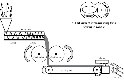
Figure 2-2A demonstrates a typical hot extrusion process for powder coatings. In the
beginning of the process, dry-mixed raw materials including resin, curing agent, pigment,
major components including the extruding screw, the heating and the cooling elements. The
hot extruder for powder coatings are normally twin-screw extruders with two to three
temperature zones. In the first zone, raw materials start to soften at elevated temperature
(40-60 oC) and the twin screws within this zone have large helical treads that push the material forward. The actual mixing begins in the second zone and the temperature is
gradually increased to 100-130 oC. The shapes of the screws in this zone become elliptical with positions shown in Figure 2-2B. In this zone, the softened materials are subjected to
high shear mixing during the inter-meshing motion of the screws. It can be an optional third
zone for ejecting the mixed material out from the extruder, although the push from the first
zone is sufficient in most of the cases. On the other hand, pre-curing of the material can
happen during hot extrusion if the temperature inside each zone is not well controlled. Any
cured material inside extruder can possibly jam the screws and any ejected pre-cured
material will most likely to cause coating defects.
The mixed material comes from the extruder is in a state of a hot paste. It is then cooled and
rolled into a solid thin sheet by two cooling drums followed by a long cooling belt. Finally,
the sheet is crushed down by a pelletizer. The end material is called the powder coating chips
which is ready for grinding.
Grinding
The grinder for processing powder coatings is a kind of the high speed impact pulveriser. As
shown in Figure 2-3, it usually has a rotor with multiple grinding elements placed on the
outer edge and a stationary annular wall with vertical grooves. The powder coating chips are
fed into the grinding chamber, while the rotor is running at a speed, generally over 110m/s.
Due to the impacts, shears and rubbings between the rotating pins and the standing grooves,
the chips will be finally broken into powders.
Figure 2-3: A grinder mill for powder coating
Three major theories were developed and used for the correlations between comminution
and the comminution energy: (1) Rittinger, in 1867, proposed that the comminution energy
was proportional to the increased surface areas. Because the comminution energy had to
increase as the particle size became smaller, so as the specific surface area became much
the material. Once the limit of the deformation was reached, the material started to break up.
Therefore, the comminution energy was only proportional to the volume or mass of the
material, but not the size [20-21]. (3) Bond, in 1952, stated that material had to break down
from cracks. While the external force was acting on the material, internal deformation
generated cracks at any weak spot. Afterward, the stresses would concentrate at the crack tip
causing further propagations, and finally, the material would split into pieces. He suggested
that the comminution energy should be inversely proportional to the square root of the
diameter of the material [20-21]. These three theories are complementary to each other.
Generally, Kick’s theory is suitable for the initial stage of the comminution process, since
the deformation of the material is large and the volume of the material increases more
remarkable. Bond’s theory can then be applied in the second stage, when cracks begin to
form. Eventually, Rittinger’s theory could be followed due to the largely increased surface
area [22].
Classifying
Classifying is the most crucial process for adjusting particle size of a powder coating
especially fine powder coatings and it is more effective than ordinary sieving process since
the agglomerations caused by the powder cohesion can be broken up by the pneumatic
energy. There are various types of classifier including the gravitational classifier or the
centrifugal classifier of cross-flow or counter-flow, cascade classifiers, rotor classifiers and
circulating air classifiers [23]. The most popular classifier for powder coatings is the
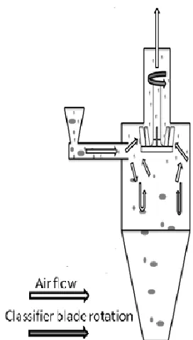
centrifugal classifier with counter-flow. Shown in Figure 2-4, particles driven by the air
stream enter the classifier and they soon encounter the high-speed classifying rotor that has a
number of vanes. Only particles that are small enough can pass through the classifying rotor,
whereas the large particles are rejected. Particles that do not pass through the classifier are
Figure 2-4: A classifier for powder coating
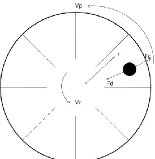
In the space between the classifier vanes, two forces are acting on a particle: the centrifugal
force and the drag force indicated by Fc, and Fd in Figure 2-5. The Fc is caused by the spin of
the particle around the shaft and the Fd is the drag force generated by the driving air. If these
two forces are equal, the particle is in equilibrium. So then the size of the particle is called
the cut-size of the classifier. The drag force will be larger, if the particle is smaller than the
cut-size; and the centrifugal force will be larger, if the particle is bigger than the cut-size.
The cut-size can be varied by enhancing or weakening the centrifugal force on the particle
caused by the increasing or decreasing the rotating speed of the vanes accordingly. On the
other hand, the cut-size can be carried by changing the air velocity. Increased or decreased
air velocity generated larger or smaller drag force on the particle so to increase or reduce the
Vp: rotational velocity of the particle; Vc: rotational velocity of the classifier blade;
r: distance from the center of the blade to the particle.
Figure 2-5: Forces acting on particle within a rotating classifier (Top view)
In the real world, the forces acting on the particles are not as simple as the theory. The
influences from air velocity gradients, turbulences and eddies are all needed to be considered.
For example, eddies generated by the air flowing through the previous vanes can disrupt the
particles being classified. As a result, large particle can possibly be driven deeper inside the
vanes causing slower circumferential velocity of the particle. Therefore, the centrifugal force
will be smaller and the particle will have a higher chance to be carried away by the escaping
air flow. On the other hand, small particle can possibly be ejected away due to the transient
out-ward drag induced by the turbulences. All these factors are going to affect the cut-size of
the classifier. The escaped large particles and ejected small particles will increase the
particle size distribution of the classified powder.
Collecting
Collecting is a necessary process because the powder coatings have to be separated from the
air after pneumatic transportations. In a mass production of powder coatings, it is always
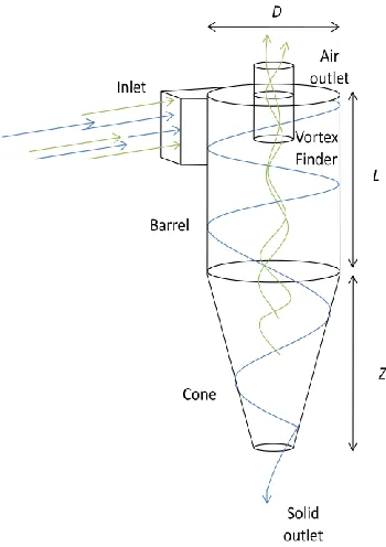
accomplished by a cyclone, which is a classic separator invented in 1800’s [24]. Cyclone is
2-6, a typical cyclone for powder coating manufacture has a tangential inlet, a cylindrical
barrel, a vortex finder, a cone and a solid outlet. Particles enter the cyclone due to the
negative pressure at the air outlet. They then flow spirally against the inner wall of the
cyclone towards the solids outlet under the combination of centrifugal and gravity forces.
But then, the majority of the air that entered with the particles escapes through the vortex
finder, while the rest of the air is flowing with the particles along the cyclone creating an
“outer vortex” [25-27]; however, the velocity of the air becomes smaller as it moves further
down the way. Eventually, the suction at the air outlet will turn the air upward and the air
flows spirally towards the vortex finder forming an “inner vortex” in the middle of the
cyclone. In the mean time, the inner vortex will carry away some of the air from the outer
vortex, known as a horizontal inward drift [25-27].
D: diameter of the cyclone barrel; L: length of the cyclone barrel;
Z: length of the cone
Many studies of cyclones by pioneer researchers were conducted to understand the
mechanism of cyclone [24-41]. In 1979, Leith discovered that the spinning gas stream is the
key factor to separation particles from the air in a cyclone due to the centrifugal effect [41].
Numerical studies disclosed that particles, on a cross-section of the cyclone, were thrown to
the cyclone wall orbiting around the center axis. In addition, the inner air flow moving
towards the vortex finder could create inward drag on the particles along the inner cyclone
wall [25-27]. Furthermore, previous studies were also focused on the collection efficiency of
cyclone [28-40]. They pointed out that the reduced collection efficiency of a cyclone was
mainly due to the loss of particles.
Ideally, a cyclone has a theoretical cut-size shown as the solid vertical line in Figure 2-7. If
particles smaller than the cut-size, the collection efficiency of the cyclone is 0% since all the
particles are removed by the drag from the air flow; and the collection efficiency is 100% for
particles that had particle sizes larger than the cut-size because the gravity and centrifugal
forces are dominant. However, the real characteristic of a cyclone follows the S-shape curve
shown as the dotted line in Figure 2-8 [28]. Stairmand found that smaller particles could
agglomerate into larger and heavier clusters [28]. These clusters were no longer dominated
by the air drag but retained inside the cyclone just like the larger particles. Furthermore, the
smaller particles may also attach to the large particles by inter-particle forces. Therefore, the
collection efficiency of the powders that had particle sizes below the cut-size was always
higher than 0%. On the other hand, large particles could escape through the inner vortex due
to the effects of turbulences, eddies and bounces. The collection efficiency above the
Figure 2-7: Diagram of grade efficiency curve characteristics [27].
For powder coatings, especially fine powder coatings, the escape of the small particles from
the cyclone is desired since the small particles can cause powder cohesion. However, the
current cyclone designs have no selectivity on the particle size. As stated above, the large
particles always escaped with the small particles causing low collection efficiency of the
cyclone. A cyclone design which can selectively remove small particles will be beneficial to
the powder coating productions.
The air classifying mill
In a powder coating plant, the processes of grinding, classifying and collecting can be
integrated into one stage operation. It is achieved by the fully automated machine called the
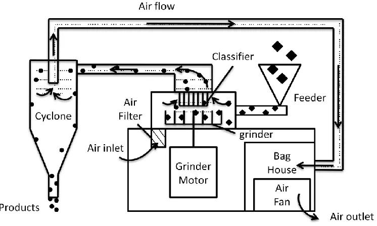
air classifying mill (ACM) shown in Figure 2-8. A continuous ACM operation is much less
labour intensive and time consuming comparing with the stage operations for each of the
Figure 2-8: A typical air classifying mill (ACM) operation
During an ACM operation, air velocity, grinder speed, feeder speed and classifier speed are
usually the four operating parameters [42]. The air velocity influences the collection
efficiency of the system. That is because a higher air velocity can increase the centrifugal
forces on the particles inside the cyclone. On the other side, the air velocity can influence the
classifying efficiency as well. More importantly, the high air flow inside the ACM can help
to reduce the temperatures from the moving components. To produce powder coatings with
finer particle sizes, classifier speed and/or grinder speed need to be increased. Other than
that, lowering the feeder speed and/or the air velocity can also help to reduce the powder
sizes. Overall, the performances of an ACM can be fully adjusted by the operating
parameters according to the grinding materials and the required particle sizes of the
produced powders. Therefore, trials are always conducted prior to the production of a
2.4 Application of Powder Coatings
The conventional liquid paints usually require large amount of solvent for suspending or
dissolving their ingredients. It can be brushed or sprayed onto a surface in thin layers and the
materials will eventually dry to form a solid coating film. In contrast, powder coatings are
more difficult to apply, since they are all solid particles which do not involve in any liquid.
There are two issues that have to be considered during powder coating applications: applying
evenly on the coating surface and melting of the particles to form a continuous coating film.
Many techniques were invented for powder coating applications and they have been refined
for decades. Some typical examples of the powder coating techniques currently used in the
industry are reviewed in the following.
Thermal spraying
Thermal spraying process is to soften and melt the powder particles during spraying. Figure
2-9 shows a diagram of a thermal spray gun. Initially, the cold compressed air is heated up
by flowing through a heat source. When the powder particles encounter the hot air, they
become softened and finally molten. And then, the molten particles impact on the surface to
build up a coating film.
Thermal spraying was the first technique that developed for powder coating application back
in late 1940s [43] and it is still being used in the industry nowadays. Thermal spraying can
provide coatings with thickness up to few mm. In addition, this application can be used
onsite since it does not require additional heating process for curing. However, the heating of
the powder is difficult to be well controlled. Therefore, it is more suitable for application of
thermal plastic materials. In addition, the resulting coating surface is rough and the bonding
between the coating and the surface is low.
Fluidized bed coating
The fluidized bed application for powder coating came out few years later after the
development of thermal spraying. It was patented by a German scientist Gemmer in 1955
[44]. Unlike the thermal spraying, the powder particles stay in room temperature during the
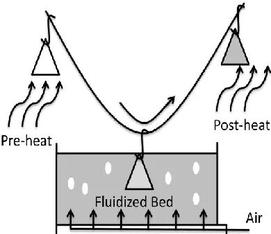
application. Instead of heating up the particles, the parts are pre-heated in this case. As
shown in Figure 2-10, the particles will begin to soften and adhere on the part when the
pre-heated part is dipped into the fluidized bed. Eventually, the coating part will be
conveyed to an oven for baking so to obtain the final coating.
The fluidized bed application can provide coatings with thickness between 150 to 500 μm
[43]. Comparing with thermal spraying, fluidized bed application provides improved coating
quality overall because of the reduced film thickness and the better control of the heating. It
can be used for both thermoplastic and thermosetting materials. Nowadays, electrostatic
charge to the parts can be used to replace the pre-heating process for better attractions of the
particles. This application method is mainly used for coatings with purposes of electrical
insulation, corrosion resistant and abrasion resistant. It still cannot be used for applying the
decorative powder coatings due to the relatively thick film and rough coating finish.
Electrostatic spraying
Electrostatic spraying developed by Pieter was first introduced to the industry in around
1963 [45]. In this application process, powder particles are charged and they are deposited
on the surface layer by layer. Since the coating part is grounded, the electrostatic forces can
firmly hold the charged particles on the part before baking. Comparing with other
application methods, electrostatic spraying can provide coating film with thickness less than
100 μm, leading to significantly improved coating finishes. Nowadays, majority of the
decorative powder coatings are applied by electrostatic spraying. There are two types of
electrostatic spraying that are commonly used: the corona charge spraying and the Tribo
charge spraying.
Corona charge spraying is the most popular way to apply powder coating because of its high
coating efficiency. As demonstrated by Figure 2-11, corona charge spraying is applied by a
corona spray gun. The spray gun has an external high voltage supply that connects to the tip
electrode inside the spraying nozzle. During spraying, negative voltage, normally between
-30 kV to -100 kV, is applied to the tip electrode. The high voltage discharged at the
![Figure 2-1: Geldart’s chart for powder classifications [1]](https://thumb-us.123doks.com/thumbv2/123dok_us/7773259.1280799/32.612.151.495.177.408/figure-geldart-s-chart-powder-classifications.webp)
![Figure 2-7: Diagram of grade efficiency curve characteristics [27].](https://thumb-us.123doks.com/thumbv2/123dok_us/7773259.1280799/44.612.135.485.80.287/figure-diagram-grade-efficiency-curve-characteristics.webp)