ISSN (Print) : 2320 – 3765 ISSN (Online): 2278 – 8875
I
nternational
J
ournal of
A
dvanced
R
esearch in
E
lectrical,
E
lectronics and
I
nstrumentation
E
ngineering
(An ISO 3297: 2007 Certified Organization)
Website: www.ijareeie.com
Vol. 6, Issue 1, January 2017
Implementation of Optimal Control Methods
for Modeling of A Power System Stabilizer in
Single Machine Infinite Bus System
Dasari Siva1, S.Shailaja2, G.N.S Vaibhav3
M.Tech, Dept. of EEE, PVKK College, Affiliated to JNTUA, AP, India1
Associate Professor, Dept. of EEE, PVKK College, Affiliated to JNTUA, AP, India2
Assistant Professor & HOD, Dept. of EEE, PVKK College, Affiliated to JNTUA, AP, India3
ABSTRACT: With the growth of interconnected power systems and particularly the deregulation of the industry, problems related to low frequency oscillation have been widely reported, including major incidents. As the most cost- effective damping controller, power system stabilizer (PSS) has been widely used to suppress the low frequency oscillation and enhance the system dynamic stability. Traditional methods for determining PSS placements are based on the analysis of the interconnected system. However, the design of the PSS is based on a simplified single machine infinite bus (SMIB) model. PSS based on simplified single machine infinite bus (SMIB) model is developed on the basis of optimal control (OP) techniques like Linear Gaussian Regulator (LGR), Linear Quadratic Regulator (LQR), H controller design, H2 controller design are represented in this paper. The MATLAB / SIMULINK model is used to implement the SMIB-PSS model.
KEYWORDS: power system stabiliser, linear Gaussian regulator (LGR), linear quadratic regulator (LQR), H controller design, H2 controller design.
I. INTRODUCTION
Power system stability is the ability of an electrical power system, for given operating conditions, to regain its state of operating equilibrium after being subjected to a physical disturbance, with the system variables bounded, so that the entire system remains intact and the service remains uninterrupted.
ISSN (Print) : 2320 – 3765 ISSN (Online): 2278 – 8875
I
nternational
J
ournal of
A
dvanced
R
esearch in
E
lectrical,
E
lectronics and
I
nstrumentation
E
ngineering
(An ISO 3297: 2007 Certified Organization)
Website: www.ijareeie.com
Vol. 6, Issue 1, January 2017
Traditionally the excitation system regulates the generated voltage and there by helps control the system voltage. The automatic voltage regulators (AVR) are found extremely suitable (in comparison to "ammortisseur winding‟ and "governor controls‟) for the regulation of generated voltage through excitation control. But extensive use of AVR has detrimental effect on the dynamic stability or steady state stability of the power system as oscillations of low frequencies (typically in the range of 0.2 to 3 Hz) persist in the power system for a long period and sometimes affect the power transfer capabilities of the system. The power system stabilizers (PSS) were developed to aid in damping these oscillations by modulation of excitation system and by this supplement stability to the system. The basic operation of PSS is to apply a signal to the excitation system that creates damping torque which is in phase with the rotor oscillations.
Because of its extensive application, the control of a nonlinear system that is uncertain is an area of study that has been very actively researched. There are efforts to apply artificial intelligent to a controller to enhance the damping of low frequency oscillations in a SMIB. This paper aims to highlight the implementation of a few prevalent optimal control methods like linear Gaussian regulator (LGR), linear quadratic regulator (LQR), H controller design, H2 controller design on the system and evaluation of the performance of each control method for use in the PSS.
II. RELATED WORK
"Improvment of power system stbility with fuzzy logic based IPFC"
The Interline Power Flow Controller (IPFC) is one of the recently developed Flexible AC Transmission System (FACTS) devices. The IPFC is realized by two voltage source converters connected by a common DC link. Fuzzy logic (FL) controllers are designed to operate the controls of IPFC for damping the power system oscillations. The proposed FL controller uses machine speed and its integral as its inputs and the output of the controller controls the input signal of the IPFC. The effectiveness of the fuzzy controller is tested on a single machine infinite bus power system operating with an IPFC for various disturbances and operating conditions. The performance of the proposed controller is compared with the conventional controller of the IPFC and the results of time-domain simulation studies show that the designed FL controller provides enhanced damping of power system oscillations.
"Synchronous Machine Stability As Affected By Excitation Contro "
This paper presents a study of the influence of the Automatic Voltage Regulator on dynamic stability of synchronous machines. The types of dynamic instabilities considered are the hunting as well as the torsional instability, while the employed AVR is that with rotating exciter, of the type 1 of IEEE. Dynamic instability is analysed by means of the concepts of electrical and mechanical torques, both synchronizing and damping. These torques are evaluated over the whole frequency range and the unstable modes are easily recognized as those with positive total damping torque. The contribution of the AVR to the damping of the unstable modes is evaluated for various loadings of the synchronous machine, for different power factors, leading or lagging, and for strong or weak transmission lines connecting the machine to the infinite bus. The analysis establishes understanding of the stabilizing requirements of excitation control. These stabilizing requirements include the AVR gain or time constants, as well as the supplementary excitation control systems.
II. CONTROL METHODS
A. DESIGN OF THE OPTIMAL H2 CONTROLLER
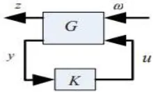
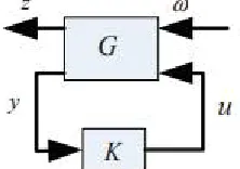
The issue with the popular H2 control is that a proper, real-rational controller K , that could internally stabilized G, have to be found. It also has to be able to minimize the H2-norm of the transfer matrix Tzw, w - z. Fig. 4, in this section, considers a system that is described by the standard block diagram that follows:
ISSN (Print) : 2320 – 3765 ISSN (Online): 2278 – 8875
I
nternational
J
ournal of
A
dvanced
R
esearch in
E
lectrical,
E
lectronics and
I
nstrumentation
E
ngineering
(An ISO 3297: 2007 Certified Organization)
Website: www.ijareeie.com
Vol. 6, Issue 1, January 2017
The transfer matrix G was taken to be in the form of the following
---- 1
For the design of the H 2 control, various D22 were selected are States with D22 = [0.2 0; 0 0.2]
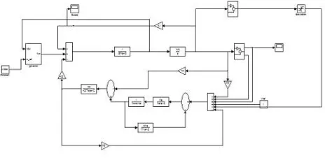
Fig 3: simulation model of H2 controller
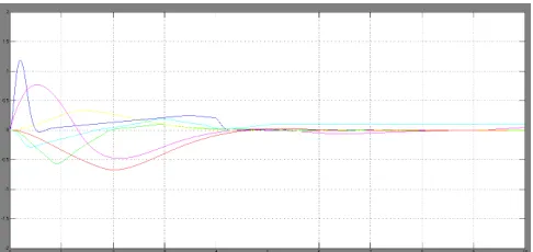
Figure 4. States with D22 = [0.2 0; 0 0.2] under H2
B. DESIGN OF THE OPTIMAL H ͚ CONTROLLER
The optimal control of H ͚ needs all of the admissible controllers K(s) to be found for ||Tzw|| to be minimised. The system that was considered is described by the block diagram as presented
ISSN (Print) : 2320 – 3765 ISSN (Online): 2278 – 8875
I
nternational
J
ournal of
A
dvanced
R
esearch in
E
lectrical,
E
lectronics and
I
nstrumentation
E
ngineering
(An ISO 3297: 2007 Certified Organization)
Website: www.ijareeie.com
Vol. 6, Issue 1, January 2017
The controller K and plant G are assumed to be proper and real-rational. The assumption is that the state space models of K and G were available. It was also assumed that the realizations of K and G could be detected and stabilized. If one recalls that a controller is considered as admissible, if it is able to stabilize the system, internally. It is obvious that for a practical system to work, the most basic requirement is stability. Therefore, it is a necessity that any sensible controller must be admissible. For the design of the H ͚ control, value for D11and D12are selected for the design of the controller. States with D11= [0 0;0 0;0 0] and D12= [0.2 0 0;0 0 0.2;0 0 0.2] under H ͚
Fig 6: simulation model of H ͚ controller
Figure 7. States with D11= [0 0;0 0;0 0] and D12= [0.2 0 0;0 0 0.2;0 0 0.2] under H ͚
C. LINEAR QUADRATIC GAUSSIAN CONTROL
Since noise in the output and state equations are considered explicitly, the LQG control is felt to be a robust technique for control. In addition, quantitative data regarding the noise is utilised in the design of the controller. Take into consideration the plant’s state space model
x(t) Ax(t) Bu(t) Γζ (t), y(t) Cx(t) θ (t) (12)
The parameters, θ(t) and ξ(t) are the noises that exist randomly present in the output measurements and the state equation. If a Kalman filter is used instead of an observer, optimal estimations of the states can be achieved. The first thing to do is to find a state estimation signal, xˆ(t) that is optimal. If it is optimal, it will minimize the
covariance E[(x−xˆ)(x−xˆ)T] . Next, the signal that has been
estimated xˆ(t) is used to take the place of the true variables of the state in a way that the problem that originated at the start is reduced to a problem of the LQ optimal control. Fig. 6 shows
ISSN (Print) : 2320 – 3765 ISSN (Online): 2278 – 8875
I
nternational
J
ournal of
A
dvanced
R
esearch in
E
lectrical,
E
lectronics and
I
nstrumentation
E
ngineering
(An ISO 3297: 2007 Certified Organization)
Website: www.ijareeie.com
Vol. 6, Issue 1, January 2017
Figure 8. LQG control structure.
The weighting parameters are selected in the design of the LQG using Matlab toolbox. These are as shown in Figs. 12 to 14 for the various Qs and:
In order to design a Kalman filter that is continuous for the values of R1, R2, R3, firstly the state space model has to be defined. Following these, the noise input matrix, the spectral density of the plant noise and measurement of the spectral density of the noise are specified, respectively to be as follows:
Subsequently, a random noise was generated for the plant and for the measurement of the measurable system states. Then, the estimated states and estimation errors are computed and the plots are illustrated in Figures 12 to 14.
Fig 9: simulation model of LQG controller
D. LINEAR QUADRATIC OPTIMAL CONTROL
The algebraic Riccati equation, (ARE) [12] was introduced for the LTI system, given by the state space model. This is given as follows:
PA AT P − PBR−1BT P Q 0
Where R and Q are the weighting matrices representing the input and state variables. The LQR problem is to solved the linear control law u(t), which is related to constant value gain matrix K, i.e.,
u(t) − Kx(t), K − R−1BT P
By choosing the weighting matrices as for the various Qs as are shown in Fig. 8 and R=1, these give the optimal performance for the states. Consequently, the closed-loop state matrix (Ac) under the LQR is obtainable using the following
ISSN (Print) : 2320 – 3765 ISSN (Online): 2278 – 8875
I
nternational
J
ournal of
A
dvanced
R
esearch in
E
lectrical,
E
lectronics and
I
nstrumentation
E
ngineering
(An ISO 3297: 2007 Certified Organization)
Website: www.ijareeie.com
Vol. 6, Issue 1, January 2017
Fig 10: simulation model of LQR controller
Figure 11. States with Q = diag [(10 50 1000 10 0 0)] under LQR
ISSN (Print) : 2320 – 3765 ISSN (Online): 2278 – 8875
I
nternational
J
ournal of
A
dvanced
R
esearch in
E
lectrical,
E
lectronics and
I
nstrumentation
E
ngineering
(An ISO 3297: 2007 Certified Organization)
Website: www.ijareeie.com
Vol. 6, Issue 1, January 2017
Figure 13. The output and estimation output for the 2nd state R1 = [0.02 0;0 0.02]
Figure 14. The measurement error and estimation outputs for the 2nd state
III. CONCLUSION
The modeling and simulation of a power system stabilizer implementing optimal control methods to choose the machine parameters during a nominal operating point are conducted. From the results, it is found that the total power output necessary to compensate the disturbance of the steady state is at an extreme amount and relative to the non-linear gain value, albeit the fact that the optimal methods created the greatest state responses. As depicted in Figures 12, 13 and 14, even at low values of measurements errors, the estimation output response generated could possibly be an oscillatory at the time of steady state condition.
REFERENCES
[1]F. Demello and C. Concordia, “Concepts of Synchronous Machine Stability as Affected by Excitation Control,” IEEE Trans. Power Appar. Syst., vol. PAS-88, no. 4, pp. 316–329, Apr. 1969.
[2]S. I. Safie, S. Majid, A. R. Hasimah, A. Wahab, and M. H. Yusri, “Sliding mode control power system stabiliser (PSS) for single machine connected to infinite bus(SMIB),” no. PECon 08, pp. 122–126, 2008.
[3]G. P. Chen, G. Y. Xu, R. Xe, and R. Ue, “Optimisation technique for the design of a linear optimal power system stabiliser,” IEEE Trans. Energy Convers., vol. 7, no. 3, pp. 453–459, 1992.
[4]J. R. and D. Dolinar, “Simple adaptive control for a power system stabiliser,” IEE Proc. - Gener. Transm. Distrib., vol. 147, no. 4, pp. 373– 380, 2000.
[5]M. K. and T. T. L. M. Zribi, M. S. Mahmoud, “H-inf controllers for linearised time-delay power systems,” IEE Proc. - Gener. Transm. Distrib., vol. 147, no. 5, 2000.
ISSN (Print) : 2320 – 3765 ISSN (Online): 2278 – 8875
I
nternational
J
ournal of
A
dvanced
R
esearch in
E
lectrical,
E
lectronics and
I
nstrumentation
E
ngineering
(An ISO 3297: 2007 Certified Organization)
Website: www.ijareeie.com
Vol. 6, Issue 1, January 2017
[7]M. W. Tsang, “Power System stibilizer utilizing power storage,” 2004 Int. Conf. power Syst. Technol. POWERCON, no. November, pp. 21–24, 2004.
[8]A. M. Parimi, I. Elamvazuthi, and N. Saad, “Fuzzy logic control for IPFC for damping low frequency oscillations,” 2010 Int. Conf. Intell. Adv. Syst., pp. 1–5, Jun. 2010.
[9]A. M. Parimi, I. Elamvazuthi, and N. Saad, “Improvment of power system stbility with fuzzy logic based IPFC,” Int. Rev. Electr. Eng., vol. 5, no. 3, pp. 1103–1109, Nov. 2010.
[10]J. Ma, K. L. Lo, and H. J. Wang, “Clarification on power system stabiliser design,” IET Gener. Transm. Distrib., vol. 7, no. 9, pp. 973– 981, Sep. 2013.
![Figure 12. The output and estimation output for the 1 st state R1 = [0.02 0;0 0.02]](https://thumb-us.123doks.com/thumbv2/123dok_us/7772223.1280225/6.595.177.419.606.721/figure-output-estimation-output-st-state-r.webp)
![Figure 13. The output and estimation output for the 2 nd state R1 = [0.02 0;0 0.02]](https://thumb-us.123doks.com/thumbv2/123dok_us/7772223.1280225/7.595.180.423.378.496/figure-output-estimation-output-nd-state-r.webp)
