Available online:
http://edupediapublications.org/journals/index.php/IJR/
P a g e | 1300Power Oscillation Damping Controller by STATCOM
1
Puli Rajinikanth,
2B. Bhaskar
1
Pursing M.Tech, Chaitanya Institute of Technology & Science, Warangal, Telangana,India
2
Asst.Prof, Chaitanya Institute of Technology & Science, Warangal, Telangana,India
Abstract:In this paper we introduce E-STATCOM (Energy Storage Static Synchronous Compensator) with MPC (Model Predictive Control) compensating the grid system with adaptive power oscillation damping. We consider an 11-bus system with four conventional sources connected through a two line transmission system. Transfer of active power and reactive power through the bus is been observed with E-STATCOM connected at different locations and compared with RLS (recursive least square) controller and MPC controller. Analysis of the design is carried out in Matlab Simulink software with all graphical representations.
Keywords: E-Statcom, MPC, RLS.
I. INTRODUCTION
To have sustainable growth and social progress, it is necessary to meet the energy need by utilizing the renewable energy resources like wind, biomass, hydro, co-generation, etc In sustainable energy system, energy conservation and the use of renewable source are the key paradigm. The need to integrate the renewable energy like wind energy into power system is to make it possible to minimize the environmental impact on conventional plant[1]. The integration of wind energy into existing power system
presents a technical challenges and that requires
consideration of voltage regulation, stability, power quality problems. The power quality is an essential customer-focused measure and is greatly affected by the operation of a distribution and transmission network. The issue of power quality is of great importance to the wind turbine [2]. There has been an extensive growth and quick development in the exploitation of wind energy in recent years. The individual units can be of large capacity up to 2 MW, feeding into distribution network, particularly with customers connected in close proximity [3]. Today, more than 28 000 wind generating turbine are successfully operating all over the world. In the fixed-speed wind turbine operation, all the fluctuation in the wind speed are transmitted as fluctuations in the mechanical torque, electrical power on the grid and leads to large voltage fluctuations. During the normal operation, wind turbine produces a continuous variable output power. These power variations are mainly caused by the effect of turbulence, wind shear, and tower-shadow and of control system in the power system. Thus, the network needs to manage for such fluctuations.
The power quality issues can be viewed with respect to the wind generation, transmission and distribution network, such as voltage sag, swells, flickers, harmonics etc. However the wind generator introduces disturbances into the distribution network. One of the simple methods of running a wind generating system is to use the induction generator connected directly to the grid system. The induction generator has inherent advantages of cost effectiveness and robustness. However; induction generators require reactive power for magnetization. When the generated active power of an induction generator is varied due to wind, absorbed reactive power and terminal voltage of an induction generator can be significantly affected. A proper control scheme in wind energy generation system is required under normal operating condition to allow the proper control over the active power production. In the event of increasing grid disturbance, a battery energy storage system for wind energy generating system is generally required to compensate the fluctuation generated by wind turbine. A STATCOM-based control technology has been proposed for improving the power quality which can technically manages the power level associates with the commercial wind turbines. The proposed STATCOM control scheme for grid connected wind energy generation for power quality improvement has following objectives.
Unity power factor at the source side.
Reactive power support only from STATCOM to wind Generator and Load.Simple bang-bang controller for STATCOM to achieve fast dynamic response.
The considered test system is shown below in fig. 1
September 2016
Available online:
http://edupediapublications.org/journals/index.php/IJR/
P a g e | 1301
II. PWM INVERTER
The pulse width modulation technique is generally used for the conversion of DC to AC waveforms. A full bridge inverter with six IGBTs can be used to convert DC to three phase AC. Each phase has to be phase shifted to each other
by 1200 and has to be in synchronization with the grid to
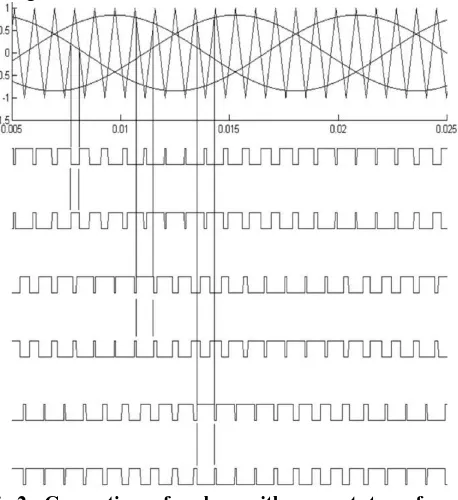
which it is being connected. The pulses are to be given to the IGBTs are generated with a reference or fundamental waveform compared with a triangular waveform. The fundamental waveform has the frequency of the grid and the triangular or carrier waveform has higher frequency to create a modulation signal. The diagram of the fundamental and the carrier waveform are shown below in fig. 3. Six pulses are formed by applying NOT gates to the three pulses produced by the comparison of the fundamental and carrier waveforms. The generated pulses are fed to the VSI (Voltage source Inverter) with G1 G2 G3 G4 G5 and G6 switches. A simple construction of VSI is shown in fig. 2.
The rating of IGBT is taken as Internal resistance Ron = 0.001 ohms Snubber resistance Rs = 100 kohms Snubber capacitance Cs = 1F
Due to the impedance load the load current gets ceased during sudden switch OFF of the IGBT switch and generate high voltage peaks in the output voltage. To avoid this an anti parallel diode is attached to the switch (IGBT) so that the inductor current from the impedance load can pass through the diode.
Fig.2. Generation of pulses with respect to reference fundamental waveforms.
The higher the carrier frequency the lower the harmonics developed by the inverter. To eliminate the minimum harmonics we also use LC filter to filter the higher order
(1)
(2)
Fig. 3. Effect of change in amplitude of sinusoidal waveform.
III. RLS ALGORITHM
The selection is a tradeoff between a good selectivity for the estimator and its speed of response. A high forgetting factor results in low estimation speed with good frequency selectivity. With increasing estimation speed (decreasing ), the frequency selectivity of the algorithm reduces. For this reason, the conventional RLS algorithm must be modified in order to achieve fast transient estimation without compromising its steady-state selectivity. In this paper, this is achieved with the use of variable forgetting factor as described in [13].
( 4) When the RLS algorithm is in steady-state, its bandwidth is determined by the steady-state forgetting factor f a rapid change is detected in the input . This frequency is dependent
The modulation index in PWM waveform is controlled by controlling the amplitude of the fundamental waveform. By reducing amplitude of the sinusoidal wave the space between the pulse is increased reducing the amplitude of the PWM waveform. The phase of the reference wave considered decides the phase of the PWM waveform.
( 3) Where Vm= maximum voltage ie., amplitude of sinusoidal waveform which is ‘1’
harmonics from the three phase AC voltage waveforms. The three sinusoidal fundamental waveforms are
Available online:
http://edupediapublications.org/journals/index.php/IJR/
P a g e | 1302on the system parameters and its operating conditions. If the no mechanical damping and the initial steady-state speed of
frequency content of the input changes, the estimator will the generators set to
give rise to a phase and amplitude error in the estimated quantities. Therefore, a frequency adaptation mechanism as described in [14] is implemented to track the true oscillation frequency of the input from the estimate of the oscillatory component.
Fig. 4. Control structure of E-STATCOM.
Fig. 5. Internal modeling of RLS control.
The mathematical model of the system in Fig. 5 is developed in this section to investigate the performance of the POD controller using active and reactive power injection. Using the expressions in (6)–(7) for
(5)
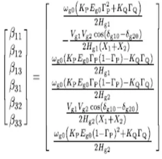
Linearizing around an initial steady-state operating point, the small-signal dynamic model of the two-machine system with the E-STATCOM in per unit is developed as in
This represents the rotor angle difference between the two generators and other signals as defined previously. Assuming
IV. SIMULINK MODEL AND RESULTS
As an example for the analysis in this section, a hypothetical 20/230 kV, 900 MVA transmission system similar to the one in Fig. 6 with a total series reactance of 1.665 p.u. and inertia constant of the generators are considered. The leakage reactance of the transformers and transient impedance of the generators are 0.15 p.u. and 0.3 p.u., respectively. The movement of the poles for the system as a function of the E-STATCOM location is shown in Fig. 7. With the described control strategy, injected active power is zero at the point where the effect of active power injection on damping is zero. This is at the electrical midpoint of the line. On the other hand, at the same location damping by reactive power injection is maximum. The reverse happens at either end of the generators. Thanks to a good control of P & Q it is also possible to see from Fig. 6 that a more uniform damping along the line is obtained by using injection of both active and reactive power.
Fig. 6. Simulink design of 11bus test system.
September 2016
Available online:
http://edupediapublications.org/journals/index.php/IJR/
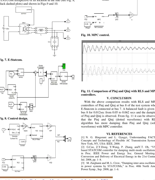
P a g e | 1303plots). With respect to reactive power injection, maximum damping action is provided when the E-STATCOM is connected close to the electrical midpoint of the line and the level of damping decreases when moving away from it (see Fig. 8, gray solid plots). Because of a good choice of signals for controlling both active and reactive power injection, effective power oscillation damping is provided by the E-STATCOM irrespective of its location in the line (see Fig. 8, black dashed plots) and shown in Figs.9 and 10.
Fig. 7. E-Statcom.
Fig. 8. Control design.
Freq 2*pi
Input Output 2*pi
1 Va bc(pu) wt
Gain RLS Error KP
eg Sin_C os
Discrete Desired Wts ifd*
3-phase PLL RLS Filter 1
ifd* ifq*
2*pi*50 ifq*
Constant
2
Input
Output
2*pi
pi/2
Ptran RLS Error KQ
0.45 Desired
Wts
Ptran* RLS Filter1
Fig. 9. RLS control.
Freq 2*pi mo mv 2*pi
1 Vabc(pu) wt
Gain MPC
KP
eg Sin_C os ref qp.status
Discrete MPC Controller1 ifd*
3-phase PLL 2*pi*50 1
ifq* ifd* ifq*
Constant
2 mo mv 2*pi
Ptran MPC pi/2 KQ
0.45 ref qp.
Ptran* MPC Controller2
Fig. 10. MPC control.
Fig. 11. Comparison of Pinj and Qinj with RLS and MPC controllers.
V. CONCLUSION
With the above comparison results with RLS and MPC controllers of Pinj and Qinj at bus 8 of the test system when E-Statcom is connected at bus 7. A balanced fault is given at bus 8 for 0.012sec from 0.05 to 0.062 secs and the damping of Pinj and Qinj is observed. From fig. 11 it can be observed that the Pinj and Qinj (dotted waveforms) with RLS algorithm has more damping than Pinj and Qinj (solid waveforms) with MPC controller.
VI. REFERENCES
[1] N. G. Hingorani and L. Gyugyi, Understanding FACTS. Concepts and Technology of Flexible AC Transmission Systems. New York, NY, USA: IEEE, 2000.
[2] G.Cao, Z.Y.Dong, Y.Wang, P. Zhang, andY.T. Oh, ―VSC based STATCOM controller for damping multi-mode oscillations,‖ in Proc. IEEE Power and Energy Soc. General Meeting— Conversion and Delivery of Electrical Energy in the 21st Century, Jul. 2008, pp. 1–8.
Available online:
http://edupediapublications.org/journals/index.php/IJR/
P a g e | 1304
[4]Z. Yang, C. Shen, L. Zhang, M. L. Crow, and S. Atcitty,
―Integration of a statcom and battery energy storage,‖ IEEE Trans. Power Syst., vol. 16, no. 2, pp. 254–260, May 2001.
[5] A. Arulampalam, J. B. Ekanayake, and N. Jenkins,
―Application study of a STATCOM with energy storage,‖ Proc. Inst. Electr. Eng.—Gener., Transm. and Distrib., vol. 150, pp. 373–384, July 2003.
[6] N. Wade, P. Taylor, P. Lang, and J. Svensson, ―Energy
storage for power flow management and voltage control on an 11 kV UK distribution network,‖ Prague, Czech Republic, CIRED paper 0824, Jun. 2009.
[7] A. Adamczyk, R. Teodorescu, and P. Rodriguez,
―Control of full-scale converter based wind power plants for damping of low frequency system oscillations,‖ in Proc. IEEE PowerTech, Trondheim, Norway, Jun. 2011, pp. 1–7.
[8] H.Xie,―On power-system benefits, main-circuit design,
control of Statcoms with energy storage,‖ Ph.D. dissertation, Dept. Electr. Energy Conversion, Royal Inst. Technol., Stockholm, Sweden, 2009.
[9] P. Kundur, Power System Stability and Control. New
York, NY, USA: McGraw-Hill, 1994.
[10] K. Kobayashi, M. Goto, K. Wu, Y. Yokomizu, and T.
Matsumura, ―Power system stability improvement by energy storage type STATCOM,‖ in Proc. IEEE Power Tech Conf., Bologna, Italy, Jun. 2003, vol. 2, DOI 10.1109/ PTC. 2003.1304302.
[11] L. Zhang and Y. Liu, ―Bulk power system low